96 Regal, 97-98 Lumina & Monte Carlo, 96-97 Cutlass Supreme , 96 Grand Prix
Lower Pinion Bearing Inspection -- 1996 Buick Regal; 1997-1998 Chevrolet Lumina, Monte Carlo; 1996-1997 Oldsmobile Cutlass Supreme; 1996 Pontiac Grand PrixThe following service procedure is for inspection of the lower pinion bearing and can be performed without completely removing the steering gear from the vehicle.
Tools Required
^ J 44714-B Pinion Bearing Remover
^ J 24319-B Steering Linkage and Tie Rod Puller
1. Open the hood.
2. Raise the vehicle on a suitable hoist and support.
3. Remove the left front tire and wheel assembly.
4. Support the rear of the engine cradle and remove the two rear cradle attaching bolts.
5. Partially lower the rear of the engine cradle.
6. Remove the bolt and separate the intermediate steering shaft from the steering gear.
7. Lower the rear of the engine cradle as necessary to access and remove the steering gear attaching bolts.
8. On models equipped with a 3.4L engine, remove the two bolts that attach the heat shield that covers the right steering gear attaching bolt. Remove the heat shield.
9. Remove the two bolts that attach the steering gear to the engine cradle.
10. Remove the nut that attaches the outer left tie rod end to the steering knuckle.
11. Using the J 24319-B, Steering Linkage and Tie Rod Puller, or equivalent, separate the outer left tie rod from the steering knuckle.
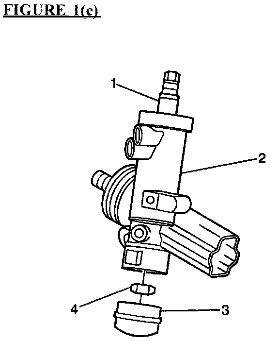
12. Remove the steering gear from the engine cradle mounting brackets and reposition to access the dust cap (3). Refer to Figure 1.
Important
When removing the dust cap in the next step, watch for loose ball hearings that may have separated from the inner and outer pinion bearing races.
13. Remove the dust cap (3) from the steering gear housing (2) and inspect for loose ball bearings. Refer to Figure 1.
^ If no ball bearings were found in the dust cap, proceed to the next step and replace the lower pinion bearing.
^ If one or more ball bearings were found loose in the dust cap, proceed to the section in this bulletin titled, "Steering Gear Replacement," for the described vehicle.
14. Reposition the steering gear as necessary to access the adjuster plug lock nut and the adjuster plug.
Notice
Failure to perform the next step may result in damage to the lower pinion bearing removal tool, J 44714-1.
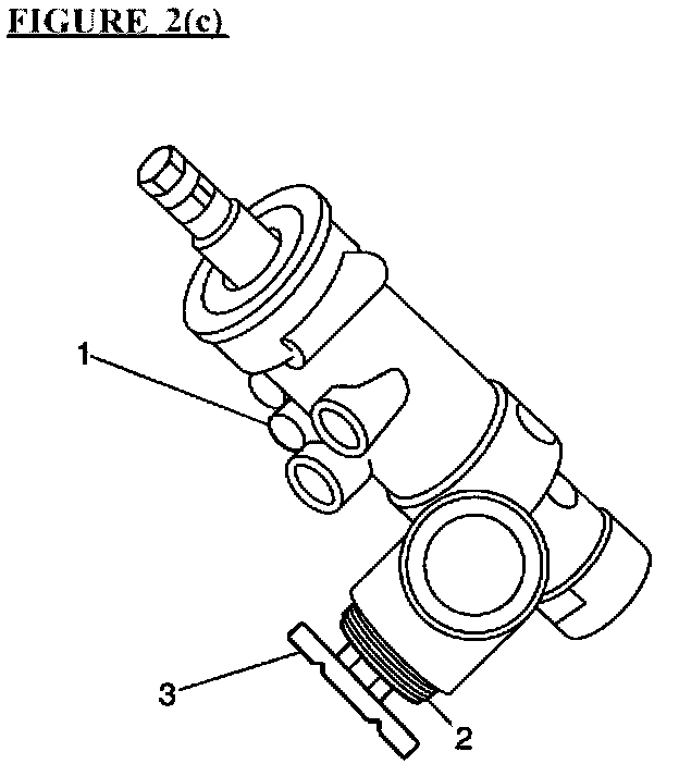
15. Loosen the adjuster plug nut (3) and the adjuster plug (2). Refer to Figure 2. Do not remove the plug.
Notice
If the stub shaft is not held in the next step, damage to the pinion teeth will occur.
16. While holding the stub shaft (1), remove the retaining nut (4) from the pinon shaft. Refer to Figure 1. Do not reuse the nut.
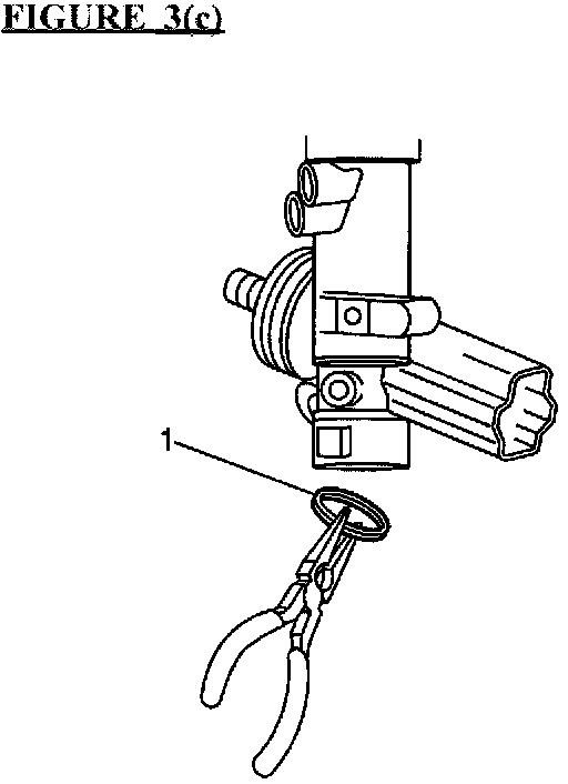
17. Remove the lower retaining snap ring (1). Refer to Figure 3.
Important
The bearing retainer being removed in the next step is a small piece of wire that keeps all the bail bearings evenly spaced inside the bearing races.
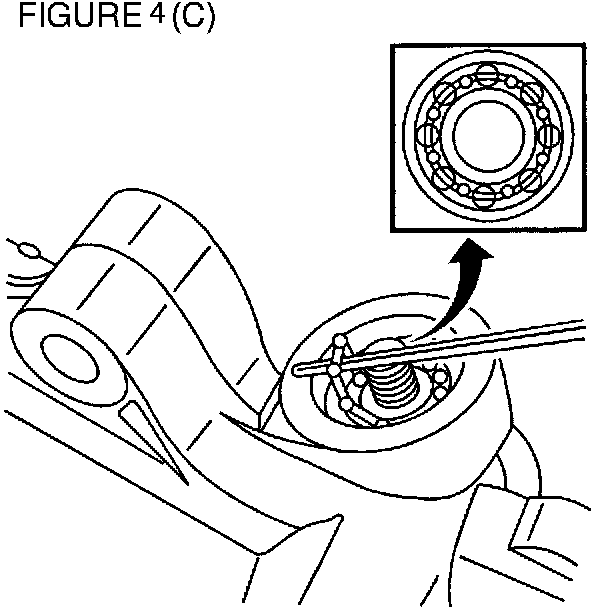
18. Using a small "pick" like tool, remove the bearing retainer from the bearing. Refer to Figure 4.
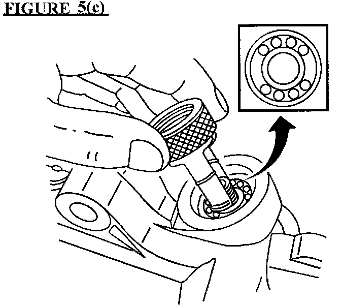
19. After removing the bearing retainer, reposition the ball bearings into two groups of four. Refer to Figure 5
20. Separate the 2-legged puller from the center nut on the J 44714-B and insert the puller legs into the openings between the two groups of ball bearings.
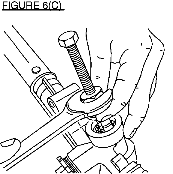
21. With the forcing screw back off, screw the center nut into the puller and tighten until the nut bottoms against the puller. Refer to Figure 6.
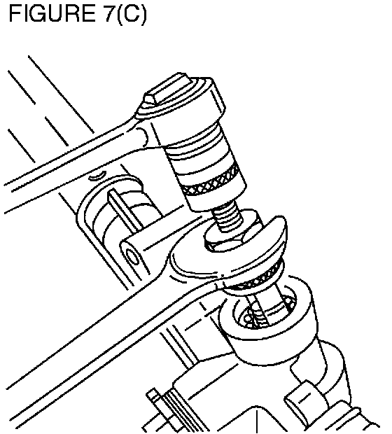
22. While holding the center nut with a wrench, tighten the forcing screw to remove the bearing from the housing. Refer to Figure 7.
Important
Inspect the gear housing to ensure that all pieces of the old bearing have been removed.
23. Apply a small quantity of lubrication (e.g., multi-purpose grease or power steering fluid) inside of the housing bore where the new bearing will be installed.
24. Center the new bearing over the pinion thread. The bearing can be installed with either side facing outwards.
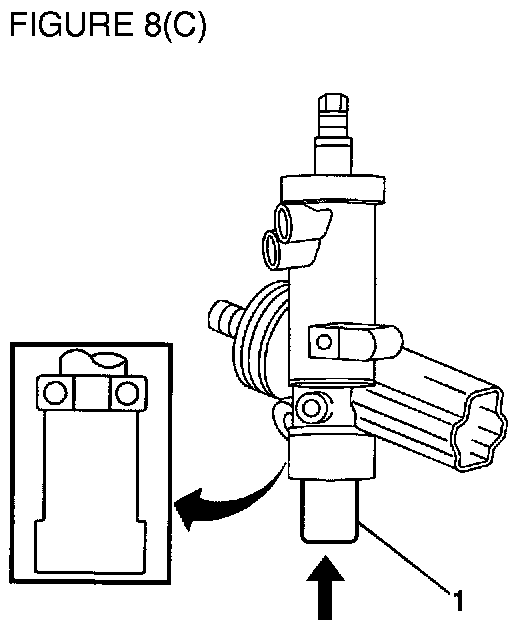
25. Place the bearing installer (1) J 44714-2 (included in J 44714-B) over the pinion thread. Refer to Figure 8. If necessary, use the extension included with the installer. Lightly tap the bearing installer with a hammer until the bearing is seated in the housing.
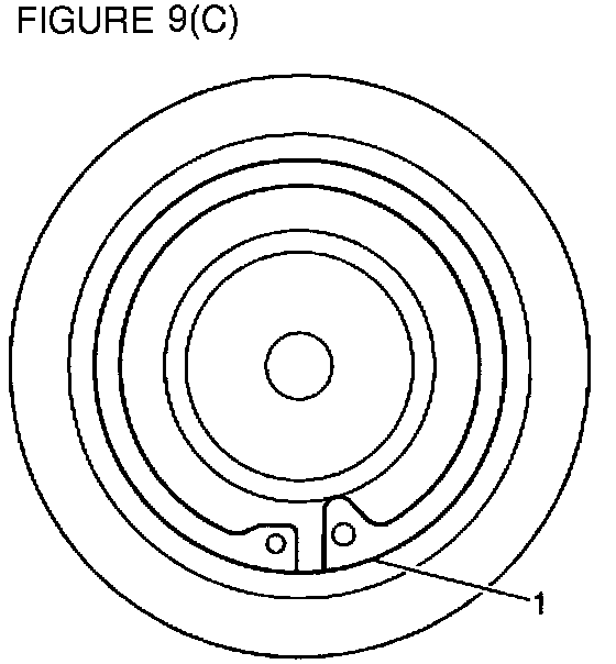
26. Install a new snap ring. When properly installed, the large lug (1) on the snap ring must be on the right side as shown in Figure 9.
Important
If the stub shaft is not held in the next step, damage to the pinion teeth will occur.
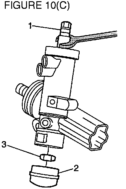
27. While holding the stub shaft (1), install a new retaining nut (3) on the pinion shaft. Refer to Figure 10.
Tighten
Tighten the nut to 30 Nm (22 lb ft).
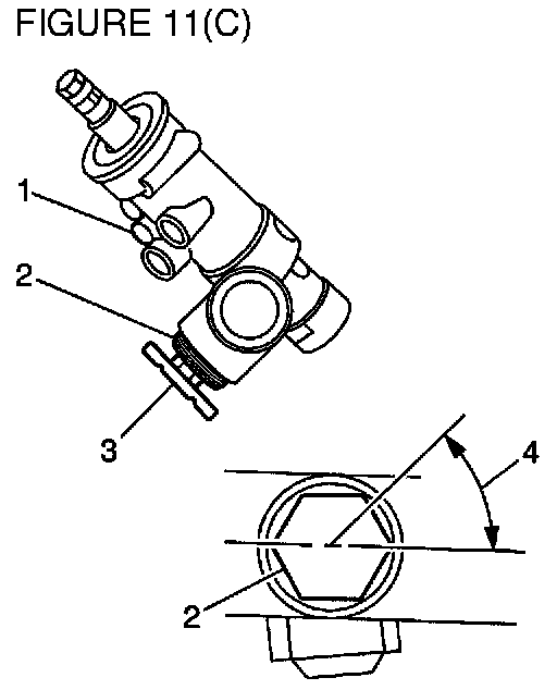
28. With the rack centered in the housing, tighten the adjuster plug (2) to 10 Nm (88 lb in), and then back off 40 to 50 degrees. Refer to Figure 11. Check the torque on the pinion. Maximum pinion preload torque is 4 Nm (35 lb in).
29. Tighten the adjuster plug lock nut (3) firmly against the steering gear housing while holding the adjuster plug (2) stationary.
30. Install a new dust cap (2) to the steering gear housing.
31. Install the steering gear in the engine cradle mounting brackets.
32. Install the steering gear attaching bolts.
Tighten
Tighten the bolts to 80 Nm (59 lb ft).
33. On models equipped with a 3.4L engine, install the heat shield and attaching bolts.
Tighten
Tighten the bolts to 6 Nm (54 lb in).
34. Install the left outer tie rod to the steering knuckle. On models with a torque prevailing nut, tighten the nut to 30 Nm (22 lb ft) and then tighten an additional 115 degrees. On models with a slotted nut and cotter pin, tighten the nut to 85 Nm (63 lb ft). If necessary, tighten the nut slightly in order to insert the cotter pin through the tie rod stud. Bend the cotter pin ends against the flats of the nuts.
35. Partially raise the rear of the engine cradle.
36. Connect the intermediate steering shaft to the steering gear and install the bolt.
Tighten
Tighten the bolt to 48 Nm (35 lb ft).
37. Raise the rear of the engine cradle and install the rear attaching bolts.
Tighten
Tighten the bolts to 180 Nm (133 lb ft).
38. Install the left front tire and wheel assembly.
Tighten
Tighten the wheel nuts to 140 Nm (103 lb ft).
39. Lower the vehicle.
40. Check the power steering fluid level and add if necessary.
41. Check the alignment and set toe-in as necessary.
42. Close the hood.
Steering Gear Replacement, If Required -- 1996 Buick Regal, 1997-1998 Chevrolet Lumina, Monte Carlo, 1996-1997 Oldsmobile Cutlass Supreme, 1996 Pontiac Grand Prix
For additional information on steering gear removal, refer to the Steering section in the appropriate Service Manual or SI.
Important
Steering gears currently available from GMSPO are verified good stock and do not require bearing inspection or replacement.
The following service procedure is based on certain steps having already been performed in the inspection procedure.
1. Remove the right front tire and wheel assembly.
2. Remove the nut that attaches the outer right tie rod end to the steering knuckle.
3. Using the J 24319-B, or equivalent, separate the outer right tie rod end from the steering knuckle.
4. If equipped, disconnect the electrical connector form the switch on the steering gear.
5. Place the steering gear back inside of the mounting brackets on the engine cradle.
6. If equipped, release the strap that attaches the power steering fluid lines to the steering gear.
7. Loosen and disconnect both power steering fluid lines from the steering gear.
8. Remove the steering gear form the vehicle.
9. Remove the tie rod ends from the original steering gear.
10. Measure the position of the adjuster nuts on the old steering gear and adjust the new nuts on the new steering gear to the same measurement.
11. Install the tie rod ends on the new steering gear.
Tighten
Tighten the adjuster nuts to 68 Nm (50 lb ft).
12. If equipped, transfer the switch to the new steering gear.
13. Install the new steering gear in the engine cradle mounting brackets.
14. Install the steering gear attaching bolts.
Tighten
Tighten to 80 Nm (59 lb ft).
15. Connect the power steering fluid lines to the steering gear.
Tighten
Tighten to 27 Nm (20 lb ft).
16. If equipped, connect the electrical connector to the switch on the steering gear.
17. On models equipped with a 3.4L engine, install the heat shield and attaching bolts.
Tighten
Tighten to 6 Nm (53 lb in).
18. Install both outer tie rod ends to the steering knuckles. On models with torque prevailing nuts, tighten the nut to 30 Nm (22 lb ft) and then tighten an additional 115 degrees. On models with a slotted nut and cotter pin, tighten the nut to 85 Nm (63 lb ft). If necessary, tighten the nut slightly in order to insert the cotter pin through the tie rod stud. Bend the cotter pin ends against the flats of the nuts.
19. Partially raise the rear of the engine cradle.
20. Connect the intermediate steering shaft to the steering gear and install the bolt.
Tighten
Tighten to 48 Nm (35 lb ft).
21. Raise the rear of the engine cradle and install the rear attaching bolts.
Tighten
Tighten to 180 Nm (133 lb ft).
22. Install both front tire and wheel assemblies.
Tighten
Tighten the wheel nuts to 140 Nm (103 lb ft).
23. Lower the vehicle.
24. Add power steering fluid and bleed the system.
25. Check the alignment and set toe-in as necessary.
26. Close the hood.