Vacuum Brake Booster: Service and Repair
TOOL REQUIRED:^ 22805-01 Booster Holder
Booster Assembly:
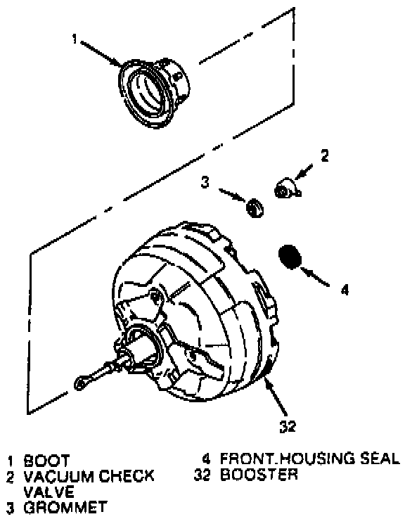
Booster Assembly Installation:
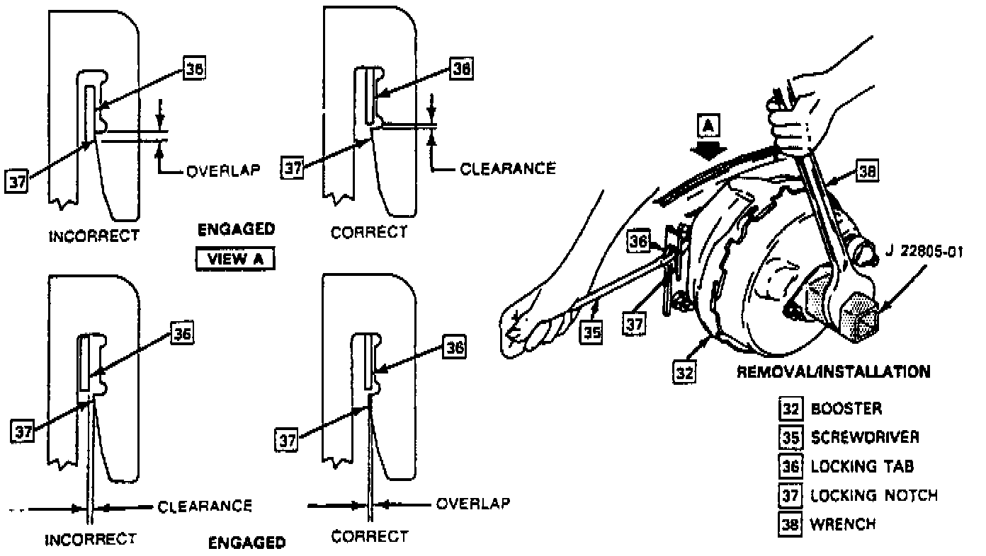
Removing And Installing Cam-lock Booster:
REMOVE OR DISCONNECT
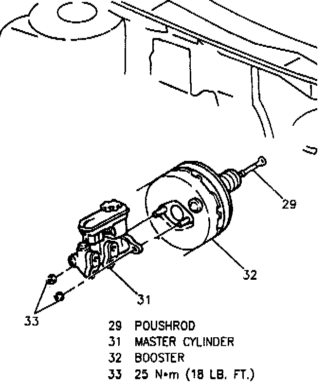
1. Nuts (33) and master cylinder (31) from booster (32).
NOTICE: When disconnecting the pushrod from brake pedal, the brake pedal must be held stationary or damage to the brake switch may result.
Booster Assembly:
2. Unlock booster (32) from front of dash.
3. Attach J 22805-01 to booster (32) with nuts (33).
TIGHTEN
^ Nuts (33) to 27 Nm (20 lb. ft.).
4. Use a screwdriver (35) to pry locking tab (36) on booster (32) out of locking notch (37) on mounting flange. At the same time turn the booster counterclockwise with a wrench (38) on J 22805-01.
NOTICE: Do not attempt to remove booster (32) until pushrod is disconnected from the brake pedal.
5. Booster pushrod (29) from brake pedal.
6. Booster (32).
^ Take care not to damage insulator boot mounted on the front of dash when pulling pushrod eye through hole.
INSTALL OR CONNECT
1. Attach J 22805-01 to booster (32) with nuts (33).
TIGHTEN
^ Nuts (33) to 27 Nm (20 lb. ft.).
2. Position booster (32) on cowl, slightly counterclockwise from final installation position, so that locking flanges on booster and mounting plate engage.
^ Take care not to damage or dislodge insulation boot when passing pushrod eye through hole.
3. Booster pushrod (29) to brake pedal.
4. Turn booster (32) clockwise with wrench (38) on J 22805-O1.
^ It is not necessary to use screwdriver (35) on locking tab (36) as shown in Figure 6 to install booster. When correctly installed, locking tab (36) will slide up flange and snap in locking notch (37).
Removing And Installing Cam-lock Booster:
IMPORTANT: Make sure locking tab (36) is fully engaged in locking notch (37).
5. Master cylinder (31) to booster (32) with attaching nuts (33).
TIGHTEN
^ Nuts (33) to 25 Nm (18 lb. ft).
ADJUST
^ Stoplamp switch.