Possible Causes
A seat belt pretensioner status fault could be caused by damaged wiring, terminals or connectors, faulty seat belt pretensioner or faulty RCM.
- Check for hard or intermittent DTC
Turn ignition switch to OFF position. Connect scan tool to Data Link Connector (DLC). See USING SCAN TOOL under DIAGNOSTICS. Turn ignition switch to RUN position. Retrieve, flag and record any continuous DTCs. See RETRIEVING FAULT CODES under DIAGNOSTICS. Perform on-demand self-test. See ON-DEMAND SELF-TEST under DIAGNOSTICS. Flag DTC B2292. See BIT-MAPPED DIAGNOSTIC TROUBLE CODES under DIAGNOSTICS. Retrieve and record any flagged faults. If DTC B2292 was retrieved during on-demand self-test, fault is hard. Go to next step. If DTC B2292 was not retrieved, fault is intermittent. Go to step 18 . - Check pretensioner
Turn ignition switch to OFF position. Disable air bag system. See DISABLING SYSTEM under DISABLING & ACTIVATING AIR BAG SYSTEM. Turn ignition switch to RUN position. Perform on-demand self-test. If DTC B2292 was retrieved during on-demand self-test, use flagged faults recorded in step 1 to find appropriate step. If flagged fault of "?" was recorded, multiple faults exist. Entire test must be carried out before replacing RCM.- For left seat belt pretensioner (DF-PTR) with low resistance (LOWRES) fault, go to next step.
- For DF-PRT with open circuit (O-CIR) fault, go to step 4 .
- For DF-PRT with short to battery (STB) fault, go to step 6 .
- For DF-PRT with short to ground (STG) fault, go to step 8 .
- For right seat belt pretensioner (PF-PTR) with low resistance (LOWRES) fault, go to step 10 .
- For PF-PRT with open circuit (O-CIR) fault, go to step 11 .
- For PF-PRT with short to battery (STB) fault, go to step 13 .
- For PF-PRT with short to ground (STG) fault, go to step 15 .
If DTC B2292 was not retrieved during on-demand self-test, use flagged faults recorded in step 1 to find appropriate step. If flagged fault of "?" was recorded, multiple faults exist. Entire test must be carried out before replacing seat belt pretensioner.
- Check left pretensioner circuit for low resistance
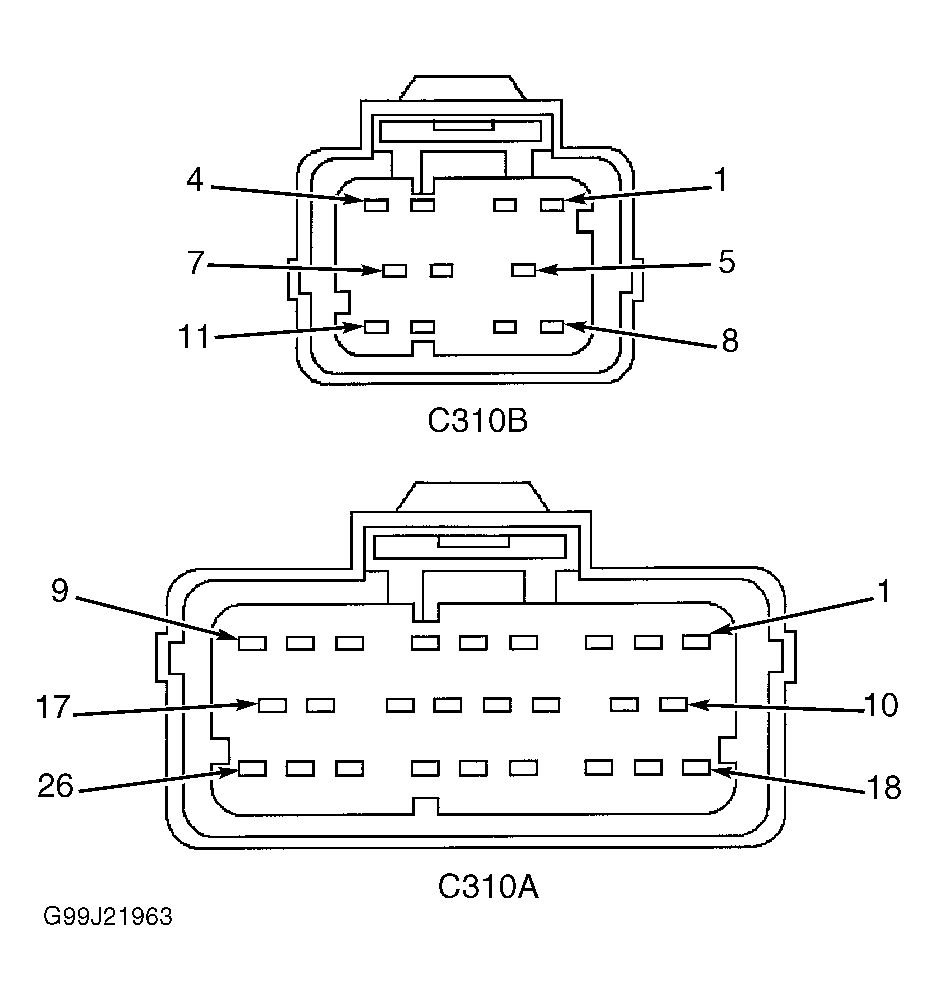
Turn ignition switch to OFF position. Access RCM and disconnect connector C310A. See RESTRAINTS CONTROL MODULE under REMOVAL & INSTALLATION. Disconnect left seat belt pretensioner simulator from harness connector. Measure resistance between harness side of RCM connector C310A, terminals No. 4 (Light Green/Black wire, circuit No. 1080) and No. 3 (Light Green/Red wire, circuit No. 1079). See Figure . If resistance is less than 10 k/ohms, repair short between Light Green/Black and Light Green/Red wires. See WIRING DIAGRAMS . Go to step 19 . If resistance is more than 10 k/ohms, go to step 17 . - Check circuit for open
Turn ignition switch to OFF position. Access RCM and disconnect connector C310A. See RESTRAINTS CONTROL MODULE under REMOVAL & INSTALLATION. Disconnect left seat belt pretensioner simulator from harness connector. Measure resistance in Light Green/Red wire (circuit No. 1079) between harness side of RCM connector C310A, terminal No. 3 and harness side of left seat belt pretensioner connector. See Figure . If resistance is less than 0.5 ohm, go to next step. If resistance is more than 0.5 ohm, repair open in Light Green/Red wire. See WIRING DIAGRAMS . Go to step 19 . - Check circuit for open
Measure resistance in Light Green/Black wire (circuit No. 1079) between harness side of RCM connector C310A, terminal No. 4 and harness side of left seat belt pretensioner connector. If resistance is less than 0.5 ohm, go to step 17 . If resistance is more than 0.5 ohm, repair open in Light Green/Black wire. Go to step 19 . - Check circuit for short to battery
Turn ignition switch to OFF position. Access RCM and disconnect connector C310A. See RESTRAINTS CONTROL MODULE under REMOVAL & INSTALLATION. Disconnect left seat belt pretensioner simulator from harness connector. Turn ignition switch to RUN position. Measure voltage between ground and harness side of RCM connector C310A, terminal No. 3 (Light Green/Red wire, circuit No. 1079). See Figure . If voltage is less than 0.2 volt, go to next step. If voltage is more than 0.2 volt, repair short to battery in Light Green/Red wire. See WIRING DIAGRAMS . Go to step 19 . - Check circuit for short to battery
Measure voltage between ground and harness side of RCM connector C310A, terminal No. 4 (Light Green/Black wire, circuit No. 1080). If voltage is less than 0.2 volt, go to step 17 . If voltage is more than 0.2 volt, repair short to battery in Light Green/Black wire. Go to step 19 . - Check circuit for short to ground
Turn ignition switch to OFF position. Access RCM and disconnect connector C310A. See RESTRAINTS CONTROL MODULE under REMOVAL & INSTALLATION. Disconnect left seat belt pretensioner simulator from harness connector. Measure resistance between ground and harness side of RCM connector C310A, terminal No. 3 (Light Green/Red wire, circuit No. 1079). See Figure . If resistance is more than one megohm, go to next step. If resistance is less than one megohm, repair short to ground in Light Green/Red wire. See WIRING DIAGRAMS . Go to step 19 . - Check circuit for short to ground
Measure resistance between ground and harness side of RCM connector C310A, terminal No. 4 (Light Green/Black wire, circuit No. 1080). If resistance is more than one megohm, go to step 17 . If resistance is less than one megohm, repair short to ground in Light Green/Black wire. Go to step 19 . - Check right pretensioner circuit for low resistance
Turn ignition switch to OFF position. Access RCM and disconnect connector C310A. See RESTRAINTS CONTROL MODULE under REMOVAL & INSTALLATION. Disconnect right seat belt pretensioner simulator from harness connector. Measure resistance between harness side of RCM connector C310A, terminals No. 7 (Yellow/Black wire, circuit No. 1082) and No. 6 (Yellow/Red wire, circuit No. 1081). See Figure . If resistance is less than 10 k/ohms, repair short between Yellow/Black and Yellow/Red wires. See WIRING DIAGRAMS . Go to step 19 . If resistance is more than 10 k/ohms, go to step 17 . - Check circuit for open
Turn ignition switch to OFF position. Access RCM and disconnect connector C310A. See RESTRAINTS CONTROL MODULE under REMOVAL & INSTALLATION. Disconnect right seat belt pretensioner simulator from harness connector. Measure resistance in Yellow/Red wire (circuit No. 1081) between harness side of RCM connector C310A, terminal No. 6 and harness side of right seat belt pretensioner connector. See Figure . If resistance is less than 0.5 ohm, go to next step. If resistance is more than 0.5 ohm, repair open in Yellow/Red wire. See WIRING DIAGRAMS . Go to step 19 . - Check circuit for open
Measure resistance in Yellow/Black wire (circuit No. 1082) between harness side of RCM connector C310A, terminal No. 7 and harness side of right seat belt pretensioner harness connector. See Figure . If resistance is less than 0.5 ohm, go to step 17 . If resistance is more than 0.5 ohm, repair open in Yellow/Black wire. Go to step 19 . - Check circuit for short to battery
Turn ignition switch to OFF position. Access RCM and disconnect connector C310A. See RESTRAINTS CONTROL MODULE under REMOVAL & INSTALLATION. Disconnect right seat belt pretensioner simulator from harness connector. Turn ignition switch to RUN position. Measure voltage between ground and harness side of RCM connector C310A, terminal No. 6 (Yellow/Red wire, circuit No. 1081). See Figure . If voltage is less than 0.2 volt, go to next step. If voltage is more than 0.2 volt, repair short to battery in Yellow/Red wire. See WIRING DIAGRAMS . Go to step 19 . - Check circuit for short to battery
Measure voltage between ground and harness side of RCM connector C310A, terminal No. 7 (Yellow/Black wire, circuit No. 1082). If voltage is less than 0.2 volt, go to step 17 . If voltage is more than 0.2 volt, repair short to battery in Yellow/Black wire. Go to step 19 . - Check circuit for short to ground
Turn ignition switch to OFF position. Access RCM and disconnect connector C310A. See RESTRAINTS CONTROL MODULE under REMOVAL & INSTALLATION. Disconnect right seat belt pretensioner simulator from harness connector. Measure resistance between ground and harness side of RCM connector C310A, terminal No. 6 (Yellow/Red wire, circuit No. 1081). See Figure . If resistance is more than one megohm, go to next step. If resistance is less than one megohm, repair short to ground in Yellow/Red wire. See WIRING DIAGRAMS . Go to step 19 . - Check circuit for short to ground
Measure resistance between ground and harness side of RCM connector C310A, terminal No. 7 (Yellow/Black wire, circuit No. 1082). If resistance is more than one megohm, go to next step. If resistance is less than one megohm, repair short to ground in Yellow/Black wire. Go to step 19 .NOTE: Ensure all air bag system simulators, sensor electrical connectors and RCM electrical connectors are connected prior to carrying out on-demand self-test or erroneous faults may be set. - Confirm RCM Fault
Turn ignition switch to OFF position. Reconnect seat belt pretensioner simulator. Reconnect both RCM connectors. Turn ignition switch to RUN position. Perform on-demand self-test. Flag DTC B2292. Retrieve and record any flagged faults. If DTC B2292 was retrieved during on-demand self-test and "?" was flagged by scan tool, carry out entire test before replacing RCM. Replace RCM. Go to step 19 . If DTC B2292 was not retrieved during on-demand self-test, fault is corrected. Go to step 19 . - Check for intermittent fault
Turn ignition to OFF position. Disable air bag system. See DISABLING SYSTEM under DISABLING & ACTIVATING AIR BAG SYSTEM. Perform on-demand self-test. Flag DTC B2292. If DTC B2292 was retrieved during on-demand self-test, check for causes of intermittent fault at or near affected seat belt pretensioner harness connector. Repair any intermittent faults found and go to next step. If intermittent fault was not found, refer to recorded flagged faults for appropriated test. If flagged fault "?" was retrieved during on-demand self-test, multiple faults exist and all steps of diagnostic procedure must be performed before replacing RCM.- For left seat belt pretensioner (DF-PRT) with low resistance (LOWRES) fault, go to step 3 .
- For left seat belt pretensioner (DF-PRT) with open circuit (O-CIR) fault, go to step 4 .
- For left seat belt pretensioner (DF-PRT) with short to battery (STB) fault, go to step 6 .
- For left seat belt pretensioner (DF-PRT) with short to ground (STG) fault, go to step 8 .
- For right seat belt pretensioner (PF-PRT) with low resistance (LOWRES) fault, go to step 10 .
- For right seat belt pretensioner (PF-PRT) with open circuit (O-CIR) fault, go to step 11 .
- For right seat belt pretensioner (PF-PRT) with short to battery (STB) fault, go to step 13 .
- For right seat belt pretensioner (PF-PRT) with short to ground (STG) fault, go to step 15 .
If DTC B2292 was not retrieved during on-demand self-test, check for cause of intermittent fault. Attempt to recreate fault by flexing wire harness and cycling ignition switch frequently. Repair any intermittent problems found. Go to next step.
- Check for additional DTCs
Refer to continuous DTCs recorded in step 1 . If any continuous DTCs were retrieved, go to diagnostic trouble code identification table for direction to appropriate test. See DIAGNOSTIC TROUBLE CODE IDENTIFICATION table. DO NOT clear any DTCs until all DTCs have been resolved. If no DTCs were retrieved, reconnect air bag system. Activate air bag system. See ACTIVATING SYSTEM under DISABLING & ACTIVATING AIR BAG SYSTEM. Clear all DTCs. See CLEARING FAULT CODES under DIAGNOSTICS.