Possible Causes
A no communication with RCM fault could be caused by damaged wiring, terminals or connectors, faulty DLC or faulty RCM.
- Check RCM connector & pin for damage
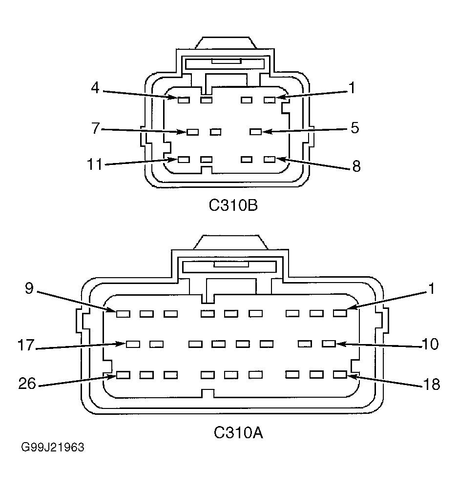
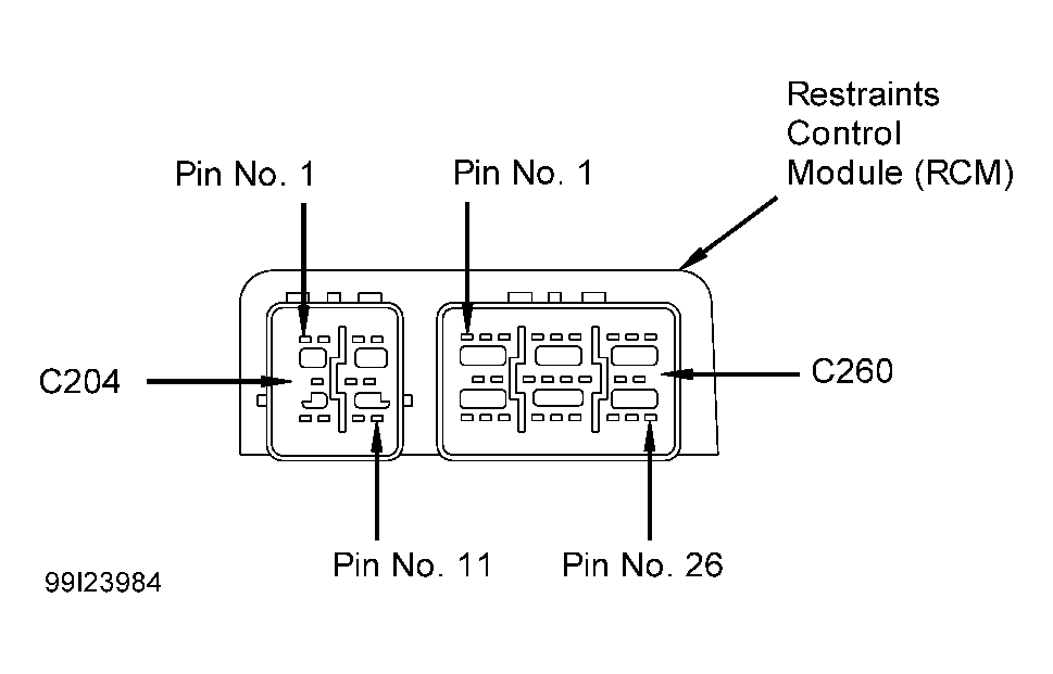
Turn ignition switch to OFF position. Disable air bag system. See DISABLING SYSTEM under DISABLING & ACTIVATING AIR BAG SYSTEM. Access RCM and disconnect connector C310B. See RESTRAINTS CONTROL MODULE under REMOVAL & INSTALLATION. Inspect both harness side and component side of RCM connector C310B, terminal No. 4 for damage, corrosion or dirt. See Figure & Figure . If no problem is found with connector or component, go to next step. If problems are found, repair RCM and/or connector as necessary. Retest communication to RCM. Activate air bag system. See ACTIVATING SYSTEM under DISABLING & ACTIVATING AIR BAG SYSTEM. - Check DLC connector & pin for damage
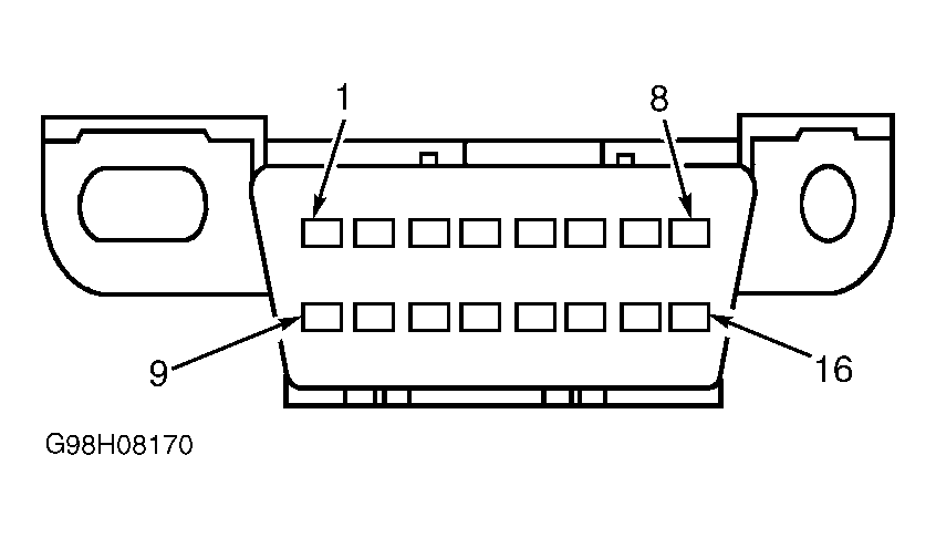
Inspect DLC connector and terminal No. 7 (Light Blue/White wire, circuit No. 70) for damage, corrosion or dirt. See Fig 1 . If no problem is found with connector or terminal, go to next step. If problem is found, repair connector or terminal as necessary. Retest communication to RCM. Activate air bag system. - Check ignition circuit for open
Turn ignition switch to RUN position. Measure voltage between ground and harness side of RCM connector C310B, terminal No. 1 (Dark Blue/Light Green wire, circuit No. 964). If voltage is 9-16 volts, go to next step. If voltage is not 9-16 volts, repair open in Dark Blue/Light Green wire. See WIRING DIAGRAMS . Retest communication to RCM. Activate air bag system. - Check ground circuit for open
Turn ignition switch to OFF position. Measure resistance between ground and harness side of RCM connector C310B, terminal No. 10 (Black wire, circuit No. 57). If resistance is less than 5 ohms, go to next step. If resistance is more than 5 ohms, repair open in Black wire. Retest communication to RCM. Activate air bag system. - Check circuit for open
Measure resistance between harness side of RCM connector C310B, terminal No. 4 and harness side of DLC connector terminal No. 7 (Light Blue/White wire). If resistance is less than 5 ohms, replace RCM. Retest communication to RCM. Activate air bag system. If resistance is more than 5 ohms, repair open in Light Blue/White wire. Retest communication to RCM. Activate air bag system.