Test D: A/C Inoperative/Does Not Operate Properly
NOTE:
If PID WACF reads ON, this is same fault as DTC P1460.
- Ensure ambient temperature is above 50°F (10°C). Turn ignition on. Turn EATC module to OFF. Perform PCM Parameter Identification WOT A/C Primary Circuit Fault (PID WACF) test. If PID WACF reads ON, perform PCM self-diagnostics. See appropriate SELF-DIAGNOSTICS article in ENGINE PERFORMANCE. If PID WACF does not read ON, go to next step.
- Perform PCM PID WAC. If PID WAC does not read ON, go to next step. If PID WAC reads ON, perform PCM self-diagnostics. See appropriate SELF-DIAGNOSTICS article in ENGINE PERFORMANCE.
- Perform PCM PID ACC. Press MAX A/C on EATC control panel. If PID ACCS reads ON, go to next step. If PID ACCS does not read ON, go to step 5.
- Perform PCM PID WAC. If PID WAC does not read ON, perform PCM self-diagnostics. See appropriate SELF-DIAGNOSTICS article in ENGINE PERFORMANCE. If PID WAC reads ON, go to step 12.
- Turn ignition off. Disconnect high pressure cut-off 4-pin harness connector C150. Turn ignition on. Measure voltage between ground and high pressure cutoff switch harness connector C150 Pink/Light Blue wire terminal. If more than 10 volts exists, go to step 10. If 10 volts or less exists, go to next step.
- Turn ignition off. Disconnect A/C cycling switch 4-pin harness connector C155. Turn ignition on. Measure voltage between ground and A/C cycling switch harness connector C155 Violet wire terminal. If more than 10 volts exists, go to next step. If 10 volts or less exists, go to step 8.
- Turn ignition off. Connect a fused jumper between A/C cycling switch harness connector C155 Violet wire terminal and Pink/Light Blue wire terminals. Turn ignition on. Measure voltage between ground and high pressure cut-off switch harness connector Pink/Light Blue wire terminal. If more than 10 volts exists, go to step 9. If 10 volts or less exists, repair open in Pink/Light Blue wire. See WIRING DIAGRAMS . Recheck system operation.
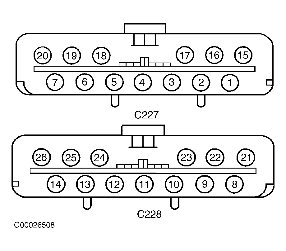
- Turn ignition off. Disconnect EATC module 13-pin harness connector C228. Measure resistance of Violet wire between EATC module harness connector C228 terminal No. 11 and A/C cycling switch harness connector. See Figure. If resistance is less than 5 ohms, replace EATC module. Recheck system operation. If resistance is 5 ohms or more, repair open or high resistance in Violet wire. See WIRING DIAGRAMS . Recheck system operation.
- Turn ignition off. Connect manifold gauge set to service ports and observe pressure. If pressure is between 50 psi (3.5 kg/cm2 ) and 250 psi (17.6 kg/cm2 ), replace A/C cycling switch. Recheck system operation. If pressure is not between 50 psi (3.5 kg/cm2 ) and 250 psi (17.6 kg/cm2 ), check refrigerant system for leaks and service as needed. Recheck system operation.
- Turn ignition off. Connect a fused jumper between A/C pressure cut-off switch harness connector C150 Pink/Light Blue wire terminal and Black/Yellow wire terminal. If A/C compressor clutch engages, replace A/C pressure cut-off switch. Recheck system operation. If A/C compressor does not engage, go to next step.
- Remove fused jumper. Disconnect PCM 104-pin harness connector C185. Connect EEC-V 104-pin breakout box to PCM harness connector. Do not connect breakout box to PCM. Measure resistance between A/C pressure cut-off switch harness connector C150 Black/Yellow wire terminal and breakout box pin No. 41. If resistance is less than 5 ohms, replace PCM. Recheck system operation. If resistance is 5 ohms or more, repair open or high resistance in Black/Yellow wire. See WIRING DIAGRAMS . Recheck system operation.
- Turn ignition off. Disconnect compressor clutch 2-pin harness connector C137. Turn ignition on. Measure voltage between ground and compressor clutch harness connector C137 Gray/White wire terminal. If more than 10 volts exists, go to next step. If 10 volts or less exists, go to step 14.
- Measure resistance between ground and compressor clutch harness connector C137 Black wire terminal. If resistance is less than 5 ohms, go to step 16. If resistance is 5 ohms or more, repair open or high resistance in Black wire. See WIRING DIAGRAMS . Recheck system operation.
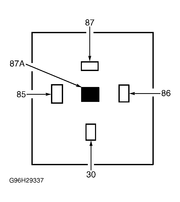
- Remove A/C WOT CUTOUT relay from relay box (located in left side of engine compartment. Measure resistance of Gray/White wire between compressor clutch harness connector C137 and A/C WOT CUTOUT relay connector socket terminal No. 87. See Fig 1. If resistance is less than 5 ohms, go to next step. If resistance is 5 ohms or more, repair open or high resistance in Gray/White wire. See WIRING DIAGRAMS . Recheck system operation.
- Turn ignition on. measure voltage between ground and A/C WOT CUTOUT relay connector socket terminal No. 30 (Violet/Orange wire). If more than 10 volts exists, go to step 17. If 10 volts or less exists, repair open in Violet/Orange wire between central junction box fuse No. 5 (15-amp) and A/C WOT CUTOUT relay. See WIRING DIAGRAMS . Recheck system operation.
- Measure A/C compressor clutch gap at 3 equally spaced positions. If A/C clutch gap is more than 0.033" (0.85 mm), adjust A/C compressor air gap to 0.014-0.033" (0.35-0.85 mm). Recheck system operation. If A/C clutch gap is not more than 0.033" (0.85 mm), replace A/C compressor clutch solenoid. Recheck system operation.
- Turn ignition on. Measure resistance between ground and A/C WOT CUTOUT relay connector socket terminal No. 85 (Pink/Yellow wire). If resistance is less than 5 ohms, replace A/C WOT CUTOUT relay. Recheck system operation. If resistance is 5 ohms or more, go to next step.
- Turn ignition off. Disconnect PCM 104-pin harness connector C185. Connect EEC-V 104-pin breakout box to PCM harness connector C185. Do not connect breakout box to PCM. Measure resistance between A/C WOT CUTOUT relay connector socket terminal No. 85 (Pink/Yellow wire) and breakout box terminal No. 69. If resistance is less than 5 ohms, replace PCM. Recheck system operation. If resistance is 5 ohms or more, repair open or high resistance in Pink/Yellow wire. See WIRING DIAGRAMS . Recheck system operation.