Test E: Blower Motor Inoperative
- Turn ignition off. Check fuse No. 9 (30-amp) in central junction box (located under dash, left side of steering column). If fuse is okay, go to next step. If fuse is blown, replace fuse. Recheck system operation. If fuse blows again, go to next step.
- Disconnect blower motor 2-pin harness connector C167. Measure resistance between ground and blower motor harness connector C167 Brown/Orange wire terminal. If resistance is more than 10 k/ohms, go to next step. If resistance is 10 k/ohms or less, repair short to ground in Brown/Orange wire between blower motor and fuse No. 9. See WIRING DIAGRAMS . Recheck system operation.
- Remove fuse No. 9. Measure resistance of Brown/Orange wire between blower motor harness connector C167 and fuse No. 9 cavity in central junction box. If resistance is less than 5 ohms, go to next step. If resistance is 5 ohms or more, repair open in Brown/Orange wire. See WIRING DIAGRAMS . Recheck system operation.
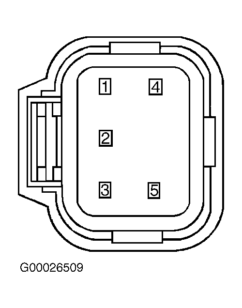
- Replace fuse No. 9. Reconnect blower motor connector. Disconnect blower motor speed controller 5-pin harness connector C169. Measure voltage between ground and blower motor controller harness connector C169 terminal No. 4 (Orange/Red wire). See Figure and Fig 1
. If more than 10 volts exists, go to next step. If 10 volts or less exists, repair open in Orange/Red wire. See WIRING DIAGRAMS . Recheck system operation.
 Courtesy of FORD MOTOR CO.
- Turn ignition off. Measure resistance between ground and blower motor speed controller harness connector C169 terminal No. 1 (Black wire). If resistance is one ohm or less, go to next step. If resistance is more than one ohm, repair open in Black wire. See WIRING DIAGRAMS . Recheck system operation.
- Connect 12 gauge jumper wire between blower motor speed controller harness connector C169 terminals No. 1 (Black wire) and No. 4 (Orange/Red wire). If blower motor operates, go to next step. If blower motor does not operate, replace blower motor. Recheck system operation.
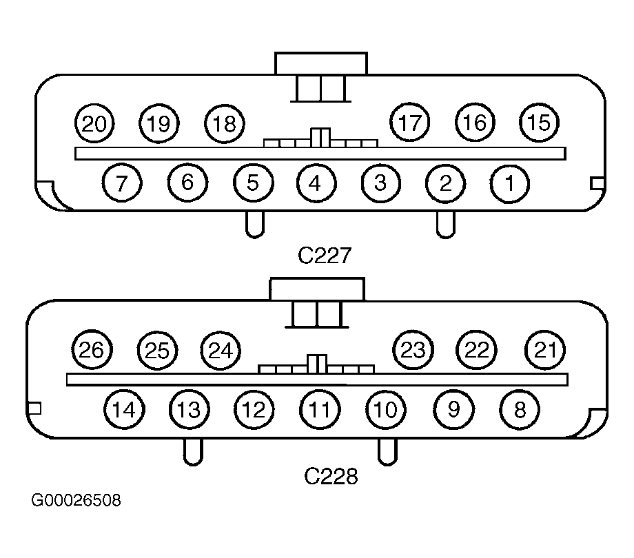
- Turn ignition off. Disconnect EATC module 13-pin harness connector C228. Measure resistance of Yellow/Red wire between EATC module harness connector C228 terminal No. 23 and blower motor speed controller harness connector C169 terminal No. 3. See Fig 1. If resistance is less than 5 ohms, go to next step. If resistance is 5 ohms or more, repair open in Yellow/Red wire. See WIRING DIAGRAMS . Recheck system operation.
- Reconnect EATC module connector. Reconnect blower motor speed controller connector. Turn ignition on. Press MAX A/C button on EATC panel. Turn blower switch to HI. Measure voltage by backprobing EATC module harness connector C228 terminals No. 3 (Black wire) and No. 23 (Yellow/Red wire). See Figure. If 1-3 volts exists, replace blower motor speed controller. Recheck system operation. If 1-3 volts does not exist, replace EATC module. Recheck system operation.