Test F: Blower Motor Operates Continuously In High Speed
- Turn ignition on. Press MAX A/C on EATC control panel. Rotate blower thumbwheel to high and then to low settings. If blower motor speed increases to high, then decreases to low, system is okay at this time. If blower speed does not respond as commanded, go to next step.
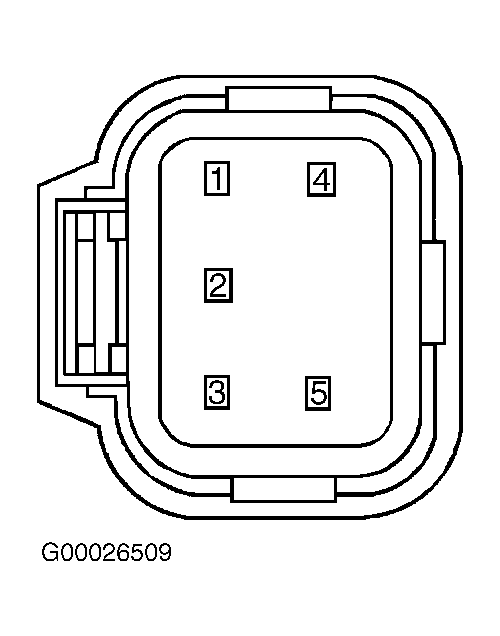
- Turn ignition off. Disconnect blower motor speed controller 5-pin harness connector C169. Turn ignition on. If blower is not running, go to next step. If blower is still running, repair short to ground in Orange/Red wire between blower motor and blower motor speed controller. See WIRING DIAGRAMS . Recheck system operation.
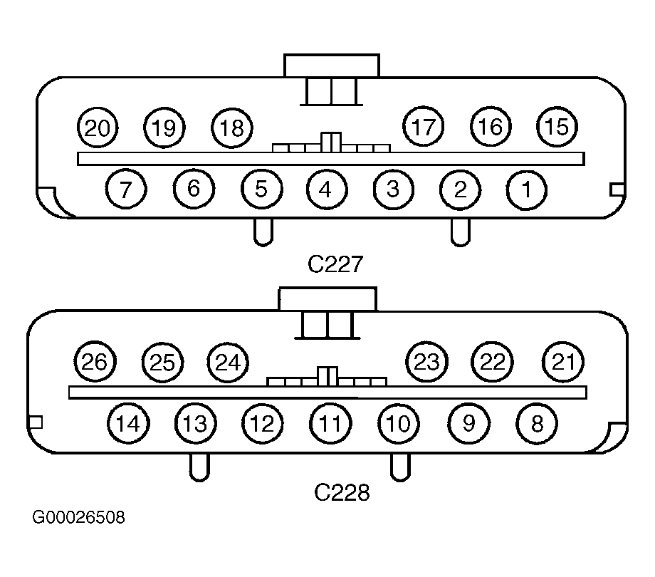
- Turn ignition off. Connect blower motor speed controller connector. Disconnect EATC module 13-pin harness connector C228. If blower motor is still running, replace blower motor speed controller. Recheck system operation. If blower motor is not running, go to next step.
- Turn ignition off. Disconnect blower motor speed controller 5-pin harness connector C169. Measure resistance of Yellow/Red wire between EATC module harness connector C228 terminal No. 23 and blower motor speed controller harness connector C169 terminal No. 3. Resistance should be 5 ohms or less. Measure resistance between ground and EATC module harness connector C228 terminal No. 23 (Yellow/Red wire). See Figure and Figure . Resistance should be more than 10 k/ohms. If resistances are as specified, go to next step. If resistances are not as specified, repair open or short in Yellow/Red wire. See WIRING DIAGRAMS . Recheck system operation.
- Measure resistance of Light Blue/Orange wire between EATC module harness connector C228 terminal No. 10 and blower motor speed controller harness connector C169 terminal No. 5. Resistance should be 5 ohms or less. Measure resistance between ground and blower motor speed controller harness connector C169 terminal No. 5 (Light Blue/Orange wire). Resistance should be more than 10 k/ohms. If resistances are as specified, go to next step. Recheck system operation. If resistances are not as specified, repair open or short in Light Blue/Orange wire. See WIRING DIAGRAMS . Recheck system operation.
- Measure resistance between ground and EATC module harness connector C228 terminal No. 24 (Light Green/White wire). If resistance is more than 10 k/ohms, go to next step. If resistance is 10 k/ohms or less, repair short to ground in Light Green/White wire. See WIRING DIAGRAMS . Recheck system operation.
- Measure resistance of Light Green/White wire between EATC module harness connector C228 terminal No. 24 and blower motor speed controller harness connector C169 terminal No. 2. If resistance is less than 5 ohms, replace EATC module. Recheck system operation. If resistance is 5 ohms or more, repair open in Light Green/White wire. See WIRING DIAGRAMS . Recheck system operation.