Test B1249: Electronic Blend Door Actuator Failure
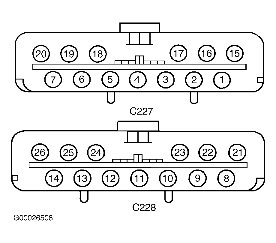
- Turn ignition off. Disconnect both EATC module 13-pin harness connectors C227 and C228. Connect jumper wire between EATC module harness connector C227 terminal No. 2 (Light Green/Yellow wire) and harness connector C228 terminal No. 26 (Violet wire). Connect second jumper wire between EATC module harness connector C227 terminal No. 3 (Black wire) and connector C228 (Brown/Light Green wire). See Figure. If blend door actuator motor moves actuator clockwise (full cool), go to next step. If blend door actuator does not move clockwise, go to step 3.
- Connect jumper wire between EATC module harness connector C227 terminal No. 2 (Light Green/Yellow wire and harness connector C228 terminal No. 13 (Brown/Light Green wire). Connect second jumper wire between EATC module harness connector C227 terminal No. 3 (Black wire) and harness connector C228 terminal No. 26 (Violet wire). If blend door actuator motor moves actuator counterclockwise (full warm), go to step 8. If blend door actuator does not move counterclockwise, go to next step.
- Disconnect blend door actuator 8-pin harness connector C282. Measure resistance between ground and EATC module harness connector C228 terminal No. 26 (Violet wire). If resistance is more than 10 k/ohms, go to next step. If resistance is less than 10 k/ohms, repair short to ground in Violet wire. See WIRING DIAGRAMS . Recheck system operation.
- Measure resistance between ground and EATC module harness connector C228 terminal No. 13 (Brown/Light Green wire). If resistance is more than 10 k/ohms, go to next step. If resistance is less than 10 k/ohms, repair short to ground in Brown/Light Green wire. See WIRING DIAGRAMS . Recheck system operation.
- Measure resistance between EATC module harness connector C228 terminal No. 26 (Violet wire) and electronic blend door actuator harness connector C282 terminal No. 7 (Violet/Orange wire). See Figure and Fig 1
. If resistance is less than 5 ohms, go to next step. If resistance is 5 ohms or more, repair open in Violet wire and/or Violet/Orange wire. See WIRING DIAGRAMS . Recheck system operation.
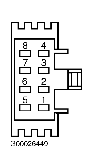 Courtesy of FORD MOTOR CO.
- Measure resistance between EATC module harness connector C228 terminal No. 13 (Brown/Light Green wire) and electronic blend door actuator harness connector C282 terminal No. 8 (Gray wire). If resistance is less than 5 ohms, go to next step. If resistance is more than 5 ohms, repair open in Brown/Light Green wire and/or Gray wire. See WIRING DIAGRAMS . Recheck system operation.
- Remove electronic blend door actuator. Connect electronic blend door connector. Disconnect actuator drive shaft from blend door. Connect jumper wires as described in steps 1 and 2. If actuator drives properly in both directions, repair blend door for blocked or binding condition. Recheck system operation. If actuator does move in both directions properly, replace blend door actuator. Recheck system operation.
- Drive blend door actuator to full COOL position as described in step 2. Measure resistance between EATC module connector C227 Red/Light Green wire and connector C228 Red/White wire. If resistance is 5-7 k/ohms, go to step 13. If resistance is not 5-7 k/ohms, go to next step.
- Disconnect electronic blend door actuator 8-pin harness connector C282. Measure resistance between EATC module harness connector C227 terminal No. 6 (Red/Light Green wire) and blend door actuator harness connector C282 terminal No. 6 (Dark Blue wire). If resistance is less than 5 ohms, go to next step. If resistance is 5 ohms or more, repair open in appropriate wire(s) between EATC module and electronic blend door actuator. See WIRING DIAGRAMS . Recheck system operation.
- Measure resistance of Red/White wire between EATC module harness connector C228 terminal No. 9 and blend door actuator harness connector C282 terminal No. 6. If resistance is less than 5 ohms, go to next step. If resistance is 5 ohms or more, repair open or high resistance in Red/White wire. See WIRING DIAGRAMS . Recheck system operation.
- Measure resistance between ground and EATC module harness connector C227 terminal No. 6 (Red/Light Green wire). If resistance is more than 10 k/ohms, go to next step. If resistance is 10 k/ohms or less, repair short to ground in Red/Light Green wire. See WIRING DIAGRAMS . Recheck system operation.
- Measure resistance between ground and EATC module harness connector C228 terminal No. 9 (Red/White wire). If resistance is more than 10 k/ohms, replace electronic blend door actuator. Recheck system operation. If resistance is 10 k/ohms or less , repair short to ground in Red/White Green wire between EATC module and electronic blend door actuator. See WIRING DIAGRAMS . Recheck system operation.
- Drive blend door actuator to full COOL position as described in step 2. Measure resistance between EATC module harness connector C227 terminal No. 18 (Yellow/Light Green wire) and EATC module harness connector C228 terminal No. 9 (Red/White wire). If resistance is 250-1500 ohms, go to step 16. If resistance is not 250-150 ohms, go to next step.
- Disconnect electronic blend door actuator 8-pin harness connector C282. Measure resistance of Yellow/Light Green wire between EATC module harness connector C227 terminal No. 18 and electronic blend door actuator harness connector C282 terminal No. 1. If resistance is less than 5 ohms, go to next step. If resistance is 5 ohms or more, repair open in Yellow/Light Green wire. See WIRING DIAGRAMS . Recheck system operation.
- Measure resistance between ground and EATC module harness connector C227 terminal No. 18 (Yellow/Light Green wire). If resistance is more than 10 k/ohms, replace blend door actuator. Recheck system operation. If resistance is 10 k/ohms or less, repair short to ground in Yellow/Light Green wire. See WIRING DIAGRAMS . Recheck system operation.
- Drive blend door actuator to full COOL position as described in step 2. Measure resistance between EATC module connector C227 terminals No. 6 (Red/Light Green wire) and No. 18 (Yellow/Light Green wire). If resistance is 3500-6000 ohms, go to next step. If resistance is not 3500-6000 ohms, replace blend door actuator. Recheck system operation.
- Measure resistance between ground and EATC module harness connector C227 terminal No. 6 (Red/Light Green wire). If resistance is more than 10 k/ohms, go to next step. If resistance is 10 k/ohms or less, repair short to ground in Red/Light Green wire. See WIRING DIAGRAMS . Recheck system operation.
- Measure resistance between ground and EATC module harness connector C228 terminal No. 9 (Red/White wire). If resistance is more than 10 k/ohms, go to next step. If resistance is 10 k/ohms or less, repair short to ground in Red/White wire. See WIRING DIAGRAMS . Recheck system operation.
- Measure resistance between ground and EATC module harness connector C227 terminal No. 18 (Yellow/Light Green wire). If resistance is more than 10 k/ohms, replace EATC module. Recheck system operation. If resistance is 10 k/ohms or less, repair short to ground in Yellow/Light Green wire. See WIRING DIAGRAMS . Recheck system operation.