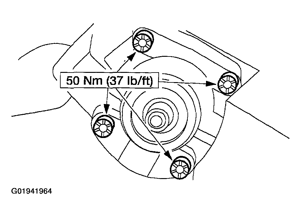
Gear - Power Steering: Assembly
- Lubricate the sector shaft seal bore.
- Use Multi-Purpose Grease DOAZ-19584-AA or equivalent meeting Ford specifications ESB-M1C93-B and ESR-M1C159-A.
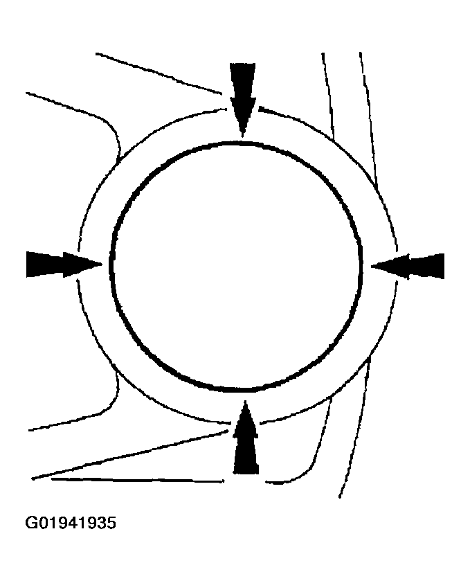
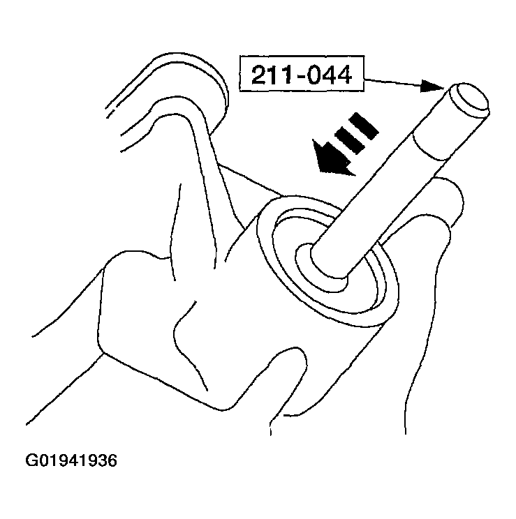
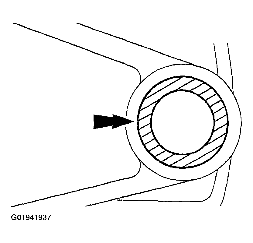
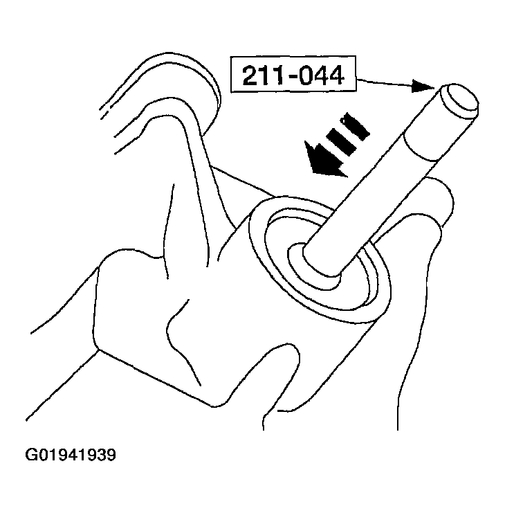
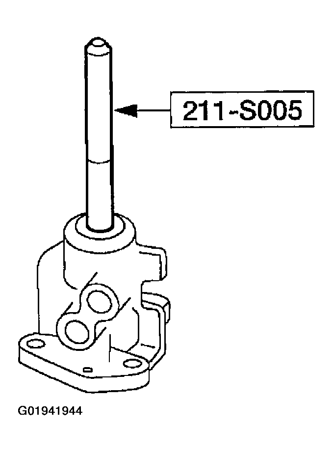
- Using the special tool, install the sector shaft seal.
- Lubricate the sector shaft seal, using Multi-Purpose Grease DOAZ-19584-AA or equivalent meeting Ford specifications ESB-M1C93-B and ESR-M1C159-A.
- Install the spacer.
- Install the snap ring.
- Using the special tool, install the sector shaft dust seal.
- Lubricate the steering gear sector shaft dust seal; use Multi-Purpose Grease DOAZ-19584-AA or equivalent meeting Ford specifications ESB-M1C93-B and ESR-M1C159-A.
- Fill the space between the steering sector shaft dust seal and the sector shaft seal with Multi-Purpose Grease DOAZ-19584-AA or equivalent meeting Ford specifications ESB-M1C93-B and ESR-M1C159-A.
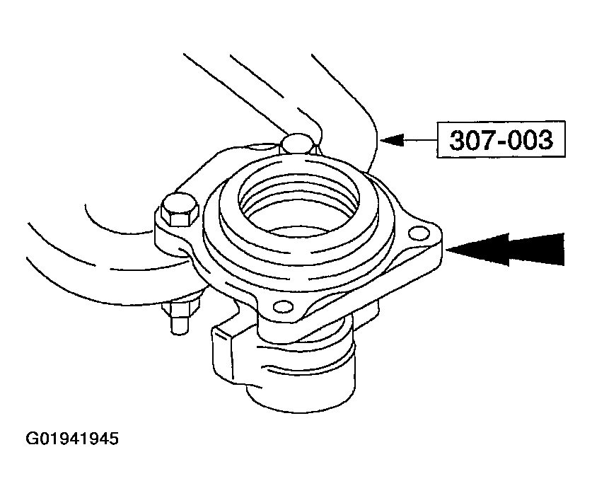
- Remove the steering gear housing from the special tool 307-003 (T57L-500-B).
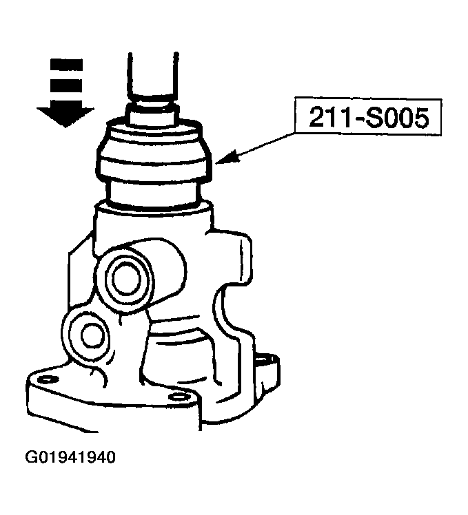
- Position the input shaft bearing in the valve housing. Using the special tool and a press, seat the input shaft bearing.
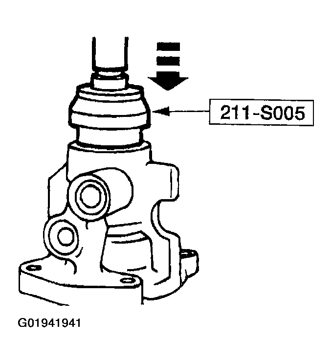
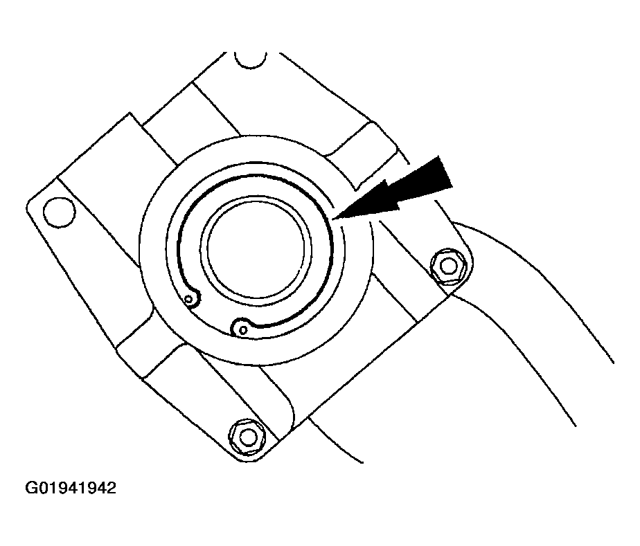
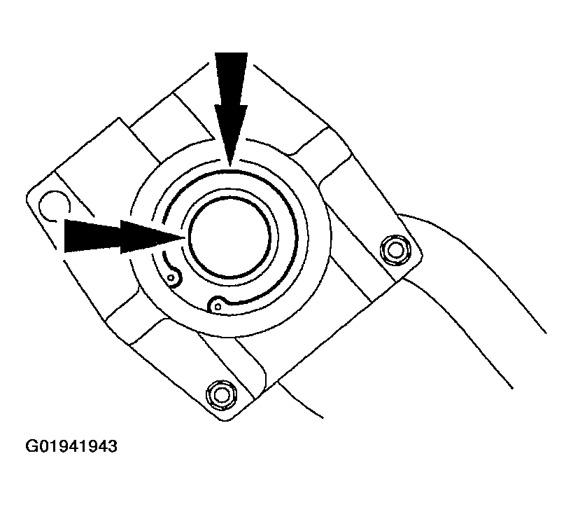
- Using the special tool, and a press, seat the power steering gear input shaft seal.
- Install the input shaft snap ring.
- Apply a liberal amount of Multi-Purpose Grease DOAZ-19584-AA or equivalent meeting Ford specifications ESB-M1C93-B and ESR-M1C159-A to the seal lip and the top surface of the power steering gear input shaft seal.
- Using the special tool, install the power steering gear input shaft dust seal.
- The dished or rubber side must face away from the valve housing.
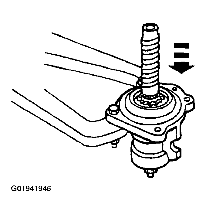
- Mount the valve housing in the special tool.
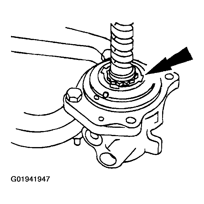
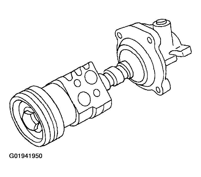
- Install the power steering gear input shaft and control into the valve housing.
- Position the power steering gear race nut into the valve housing.
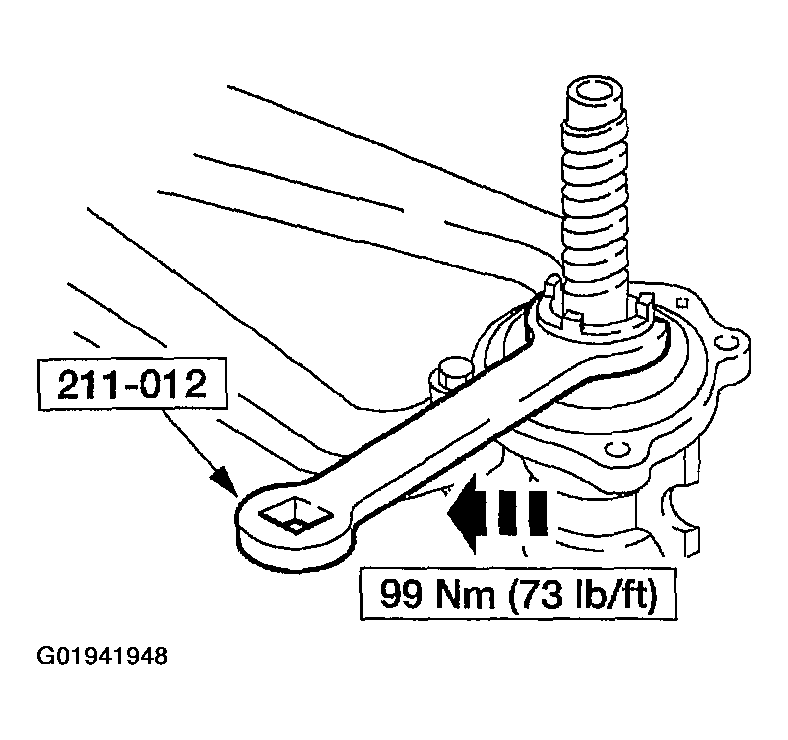
- Using the special tool, tighten the race nut.
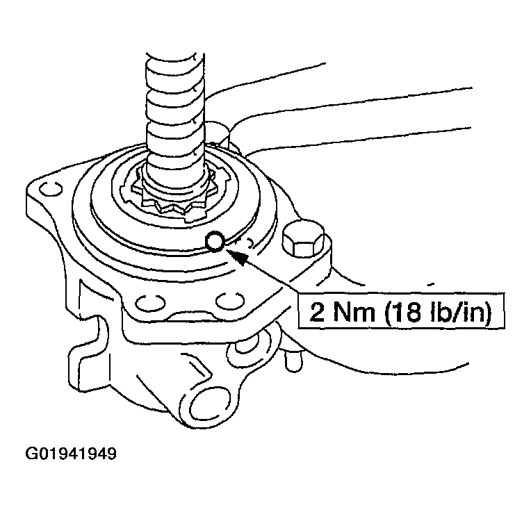
- Install the setscrew.
- Remove the valve housing from the special tool 307-003 (T57L-500-B). Position the piston on the worm gear.
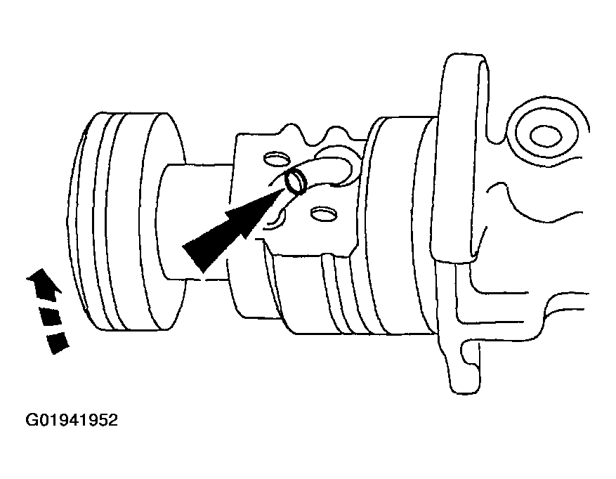
- Install the steering gear ball return guide on the piston.
- Rotate the piston while holding the steering gear ball return guide and install the 27-29 ball bearings into the opening in the ball guide.
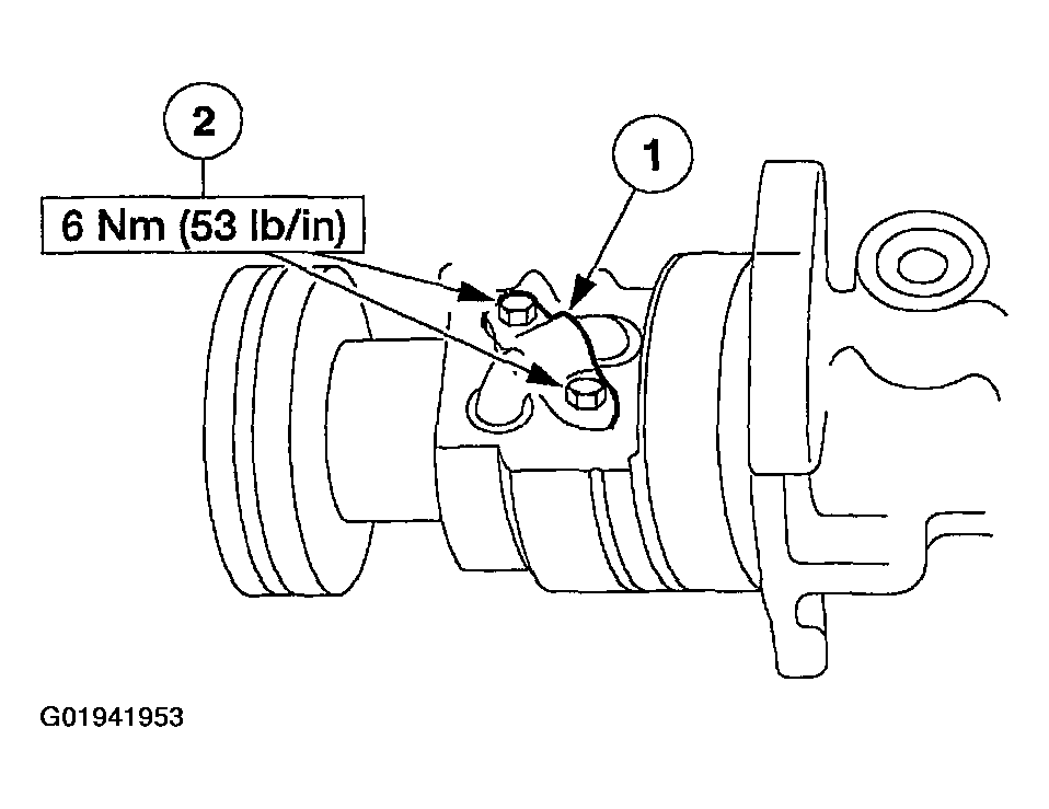
- Install the steering gear ball return guide clamp.
- Position the steering gear ball return guide clamp.
- Install the bolts.
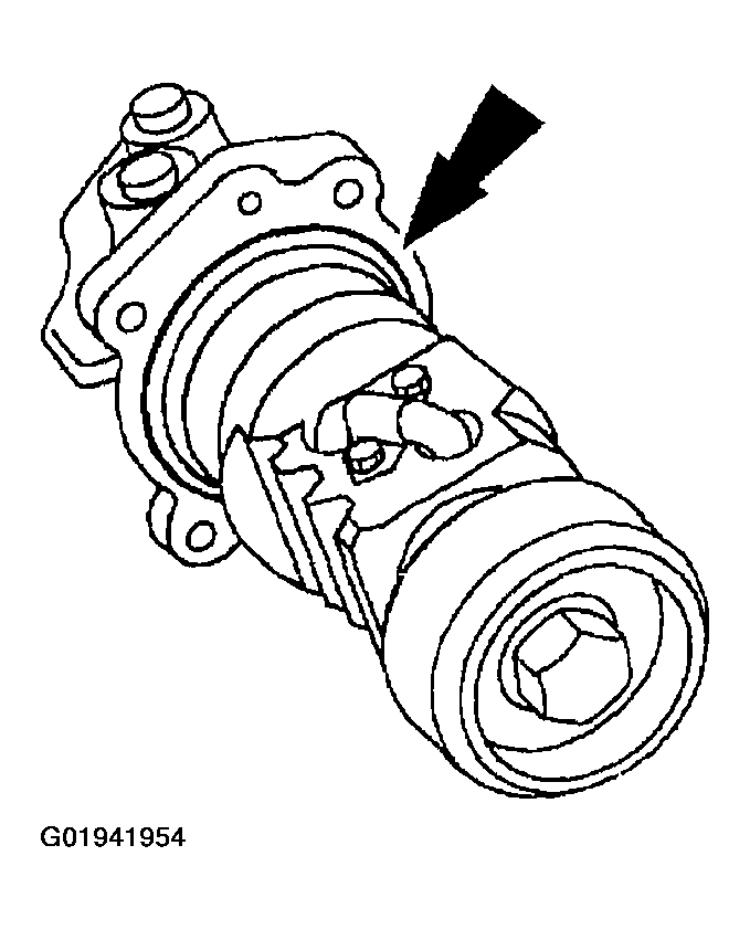
- Install a new seal ring.
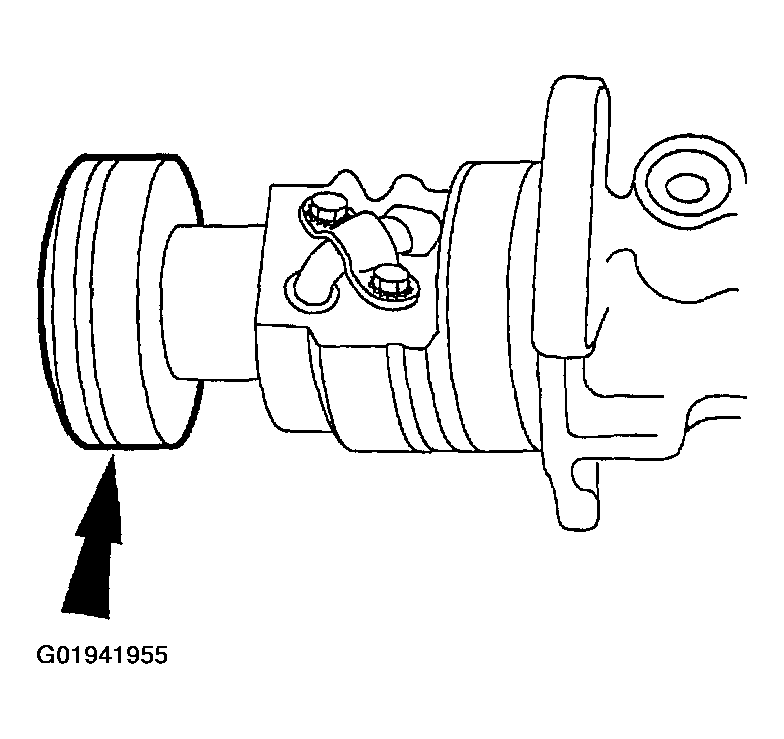
- Lubricate and install the seal on the piston.
- Use Multi-Purpose Grease DOAZ-19584-AA or equivalent meeting Ford specifications ESB-M1C93-B and ESR-M1C159-A.
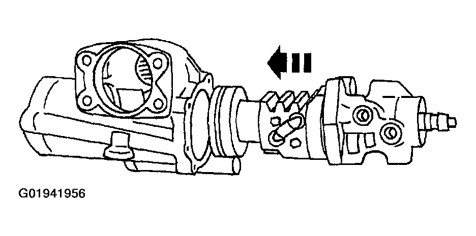
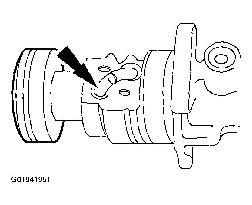
- Install the piston assembly into the steering gear housing. Make sure to align the oil passages in the steering gear housing.
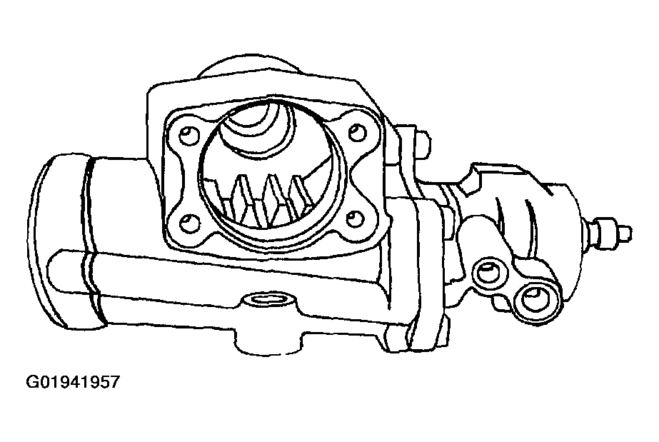
- Rotate the teeth so they are on the same plane as the steering gear sector shaft.
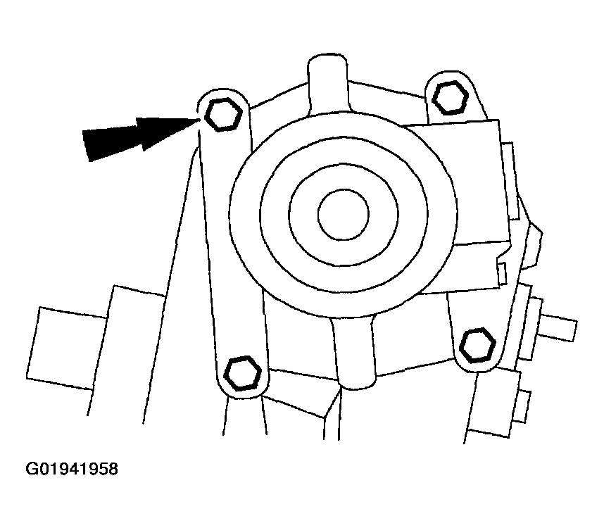
- Loosely install the valve housing bolts and the identification tag, if so equipped.
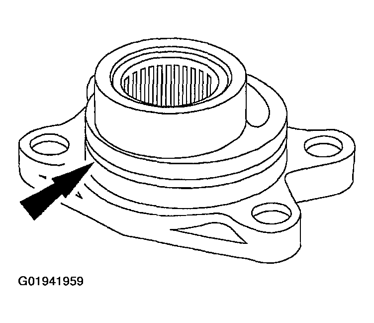
- Lubricate the O-ring on the sector shaft housing cover.
- Use Multi-Purpose Grease DOAZ-19584-AA or equivalent meeting Ford specifications ESB-M1C93-B and ESR-M1C159-A.
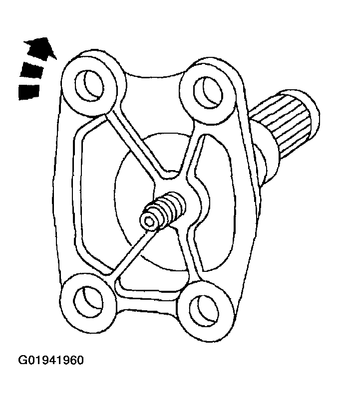
- Rotate the housing clockwise and install the sector shaft into the sector shaft housing.
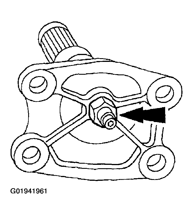
- Install the sector shaft lock nut. The sector shaft lock nut will be tightened during the steering gear meshload adjustment.
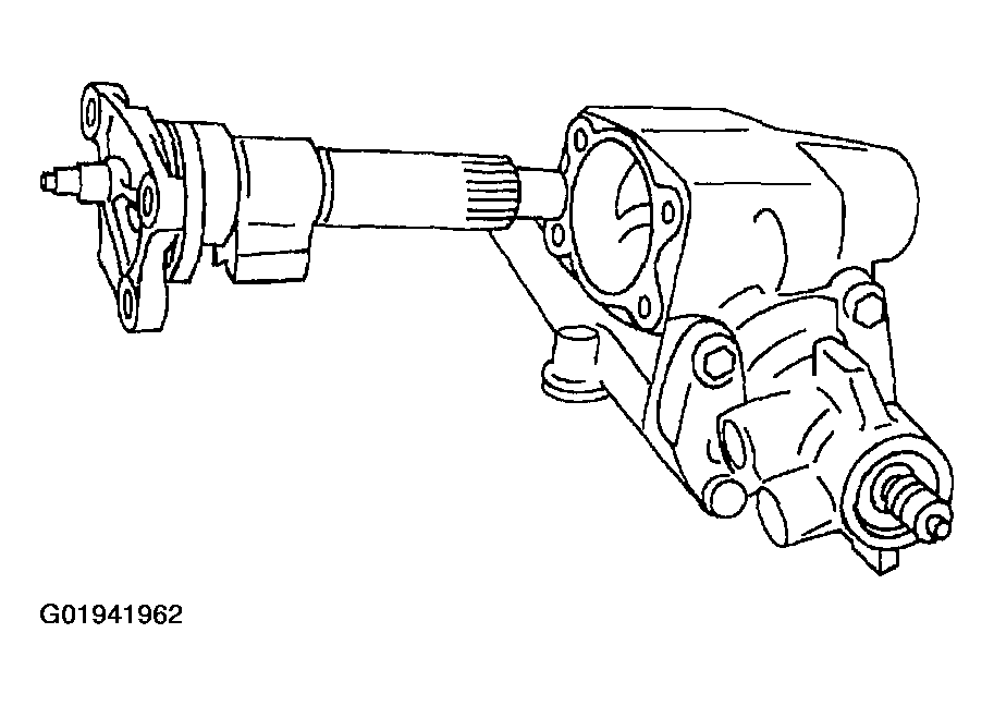
- Install the sector shaft and housing assembly. Loosely install the sector shaft housing bolts.
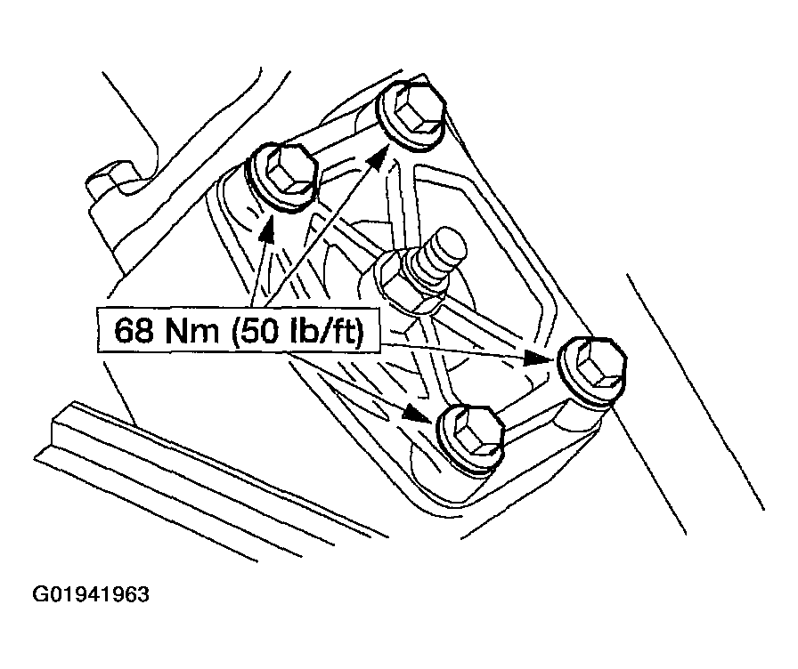
- Tighten the bolts.
- Tighten the bolts.
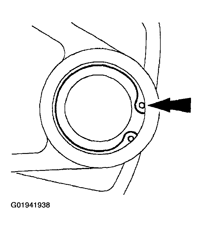
NOTE:
Place the steering gear sector shaft dust seal on the special tool so the raised lip is toward the tool.
WARNING:
Hold the ball return guides until the cap or clip is reinstalled. Failure to hold the guides will result in a trapped ball or balls, which could cause a vehicle accident. If the ball guides become unseated at any time, remove all the balls and repeat the procedure.
WARNING:
The correct number of balls are required for proper gear operation. Count the balls and insert each carefully.
WARNING:
To make sure the balls are correctly installed, rotate the steering gear input worm gear and rack from one end of travel to the other without allowing the poppet adjuster to contact the valve housing or moving the valve housing pilot face more than 69.1 mm (2-3/4 inches) from the input end of the rack piston. If the steering gear input worm gear and rack cannot be rotated, reinstall the balls. If a steering gear is installed with a steering gear input worm gear and rack that cannot rotate, the steering gear will not function correctly and steering and gear failure can result.