Evaporator Core Housing: Removal
- Disconnect negative battery cable. Discharge A/C system, using approved recovery/recycling equipment. See RECOVERY, EVACUATION & RECHARGING in GENERAL SERVICING PROCEDURES article in GENERAL SERVICING. Drain radiator so that coolant level is below heater core. Raise and support vehicle.
- Remove right front wheel. Remove screws from right front fender apron and remove fender apron. See Fig 1. Remove nuts. See Fig 2. Lower vehicle.
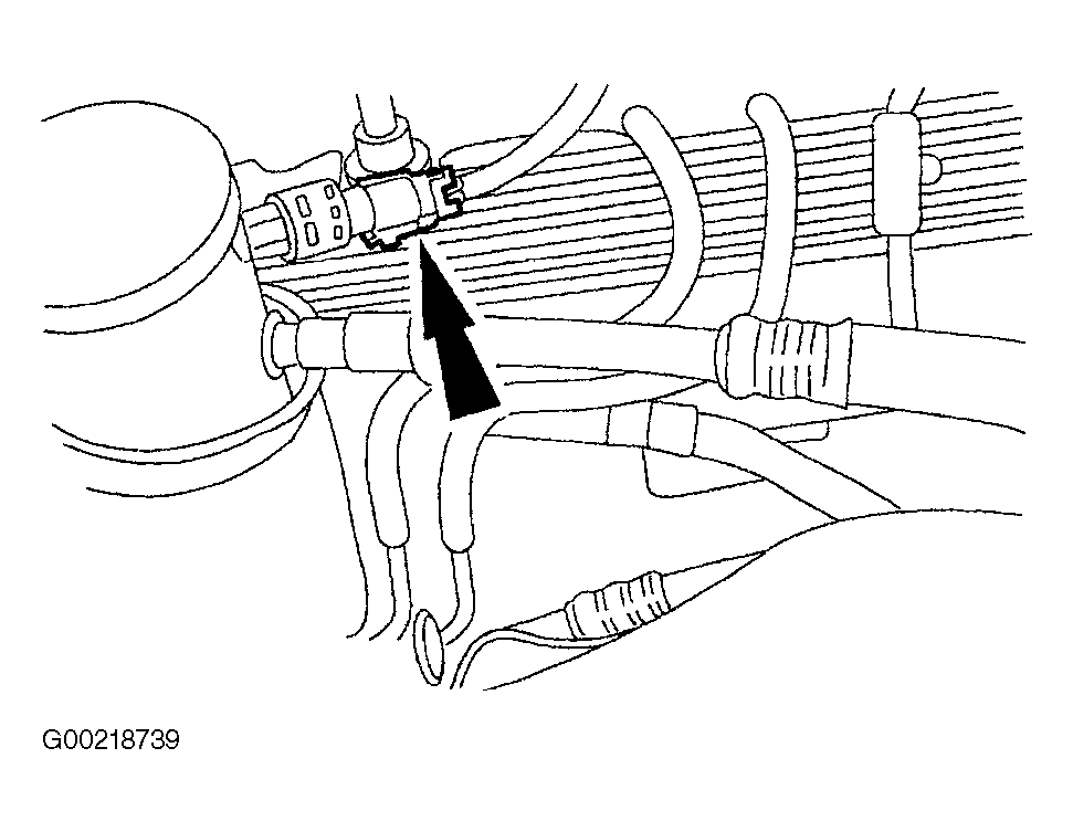
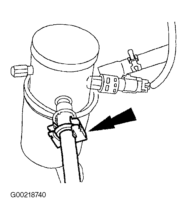
- Remove blower motor switch resistor. Disconnect A/C cycling switch wire harness connector. See Figure. Disconnect evaporator core to compressor suction line from accumulator-drier. See Figure. See SPRING LOCK COUPLING .
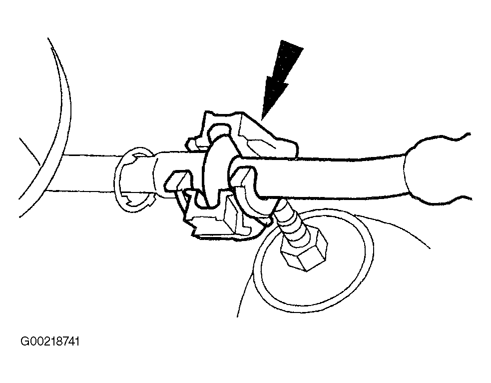
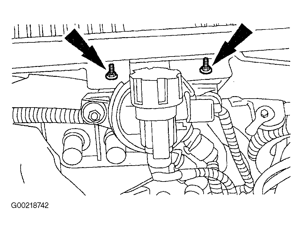
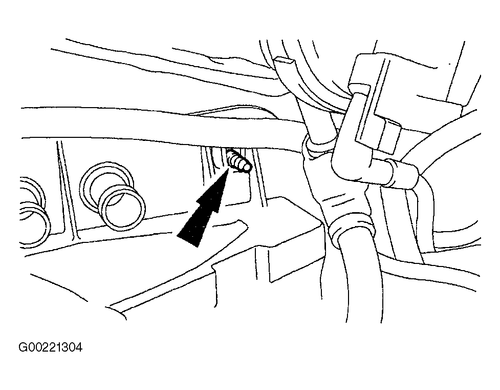
- Disconnect condenser core to evaporator core tube from evaporator core inlet tube. See Fig 3. Remove nuts and position purge valve and bracket away from evaporator core housing. See Fig 4.
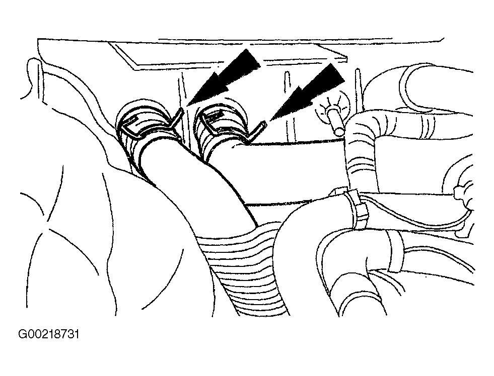
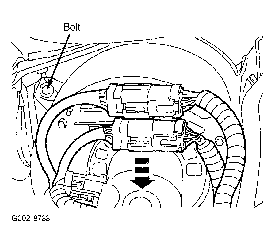
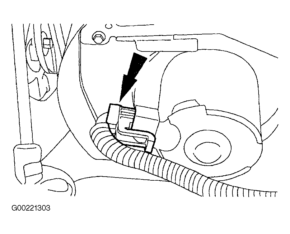
- Remove heater hoses from heater core. See Figure. Disengage connectors from bracket. See Figure. Disconnect wire harness connector. See Fig 5.
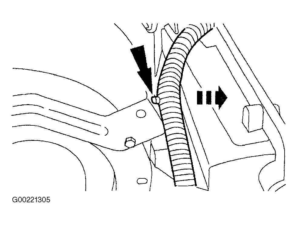
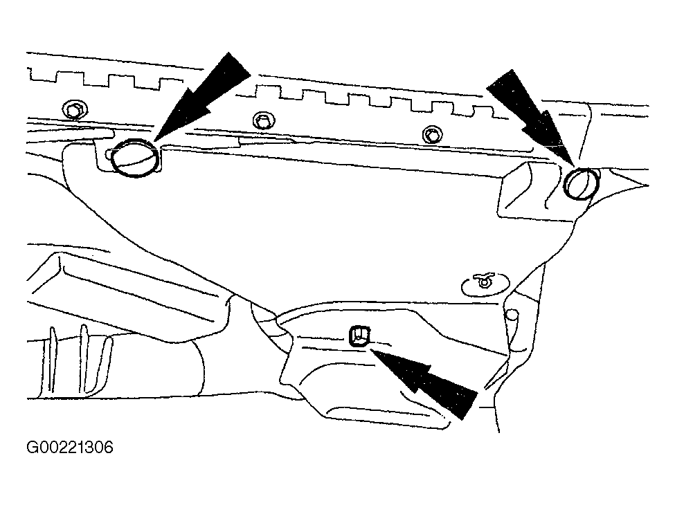
- Remove nut and reposition wire harness away from evaporator core housing. See Fig 6. Disengage harness from bracket. See Fig 7. Remove pin-type retainer and clip then remove instrument panel lower insulator. See Fig 8.
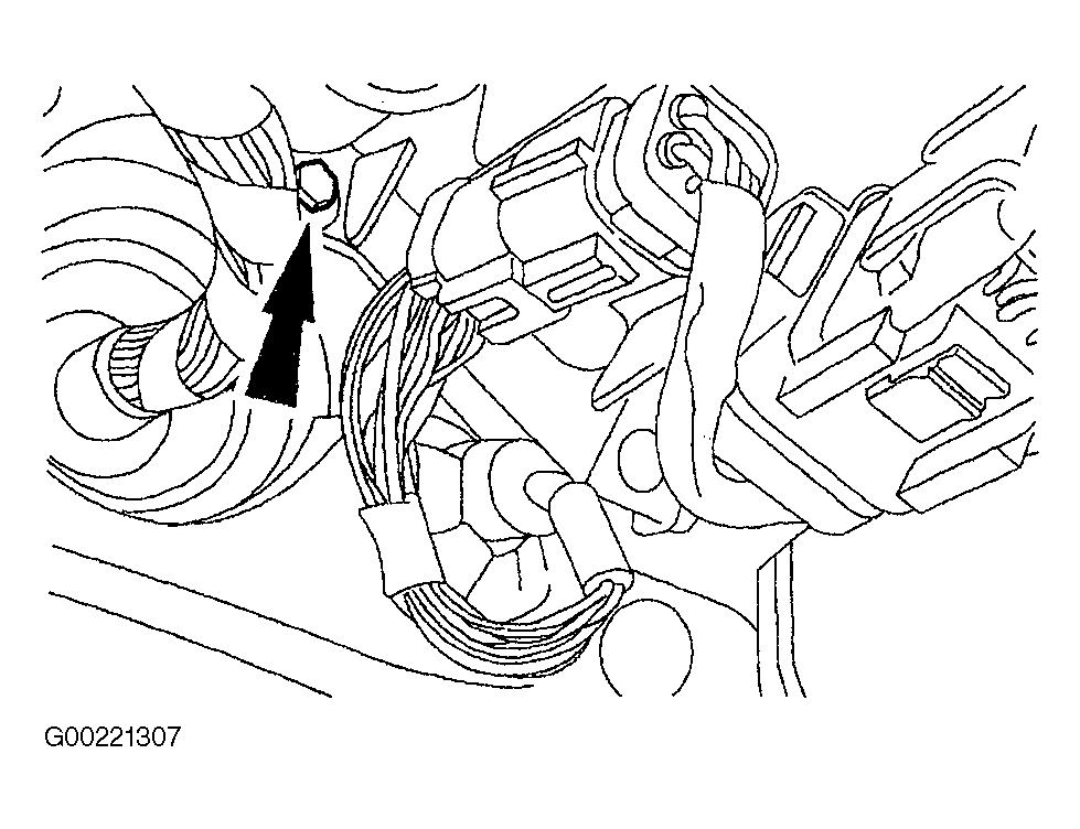
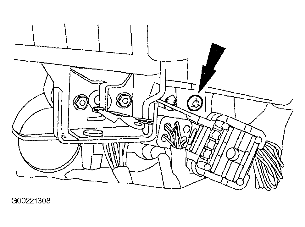
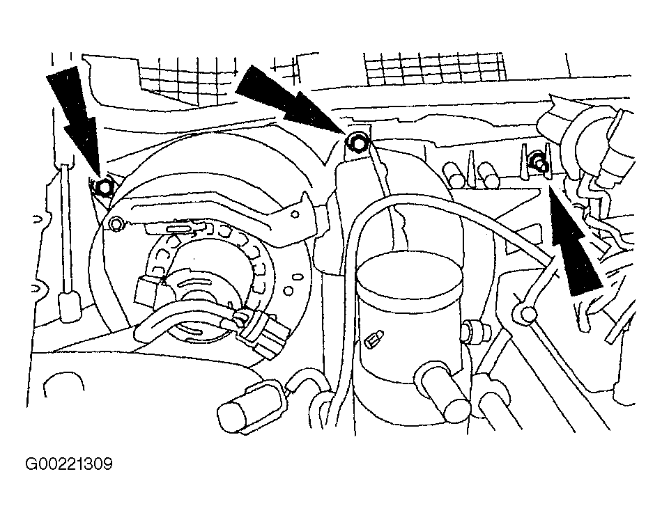
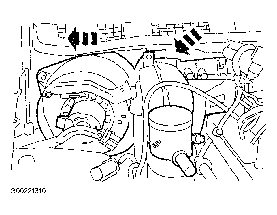
- Fold back carpet and remove screw. See Fig 9. Inside vehicle, remove screw. See Fig 10. Remove engine side nuts. See Fig 11. Remove evaporator core housing. See Fig 12.
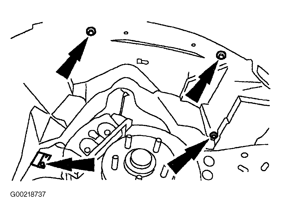
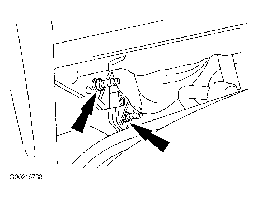
Fig 3: Disconnect & Reconnecting Condenser Core-To-Evaporator Core Tube From Evaporator Core Inlet Tube
 Courtesy of FORD MOTOR CO.
 Courtesy of FORD MOTOR CO.