LEMON Manuals: Even more car manuals for everyone: 1960-2025
Home >> Ford >> 2002 >> Crown Victoria Base, 4.6 9 >> Repair and Diagnosis >> Engine Mechanical >> Mechanical >> Engine - 4.6L >> In-Vehicle Repair >> Intake Manifold - Gasoline Engines >> Installation

Intake Manifold - Gasoline Engines: Installation

    NOTE: Align the gasket tabs with the slots in the block.
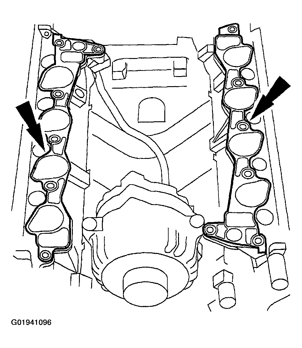
    Fig 1: Identifying Intake Manifold Gaskets
    G01941096Courtesy of FORD MOTOR CO.
  1. Install the new intake manifold gaskets.
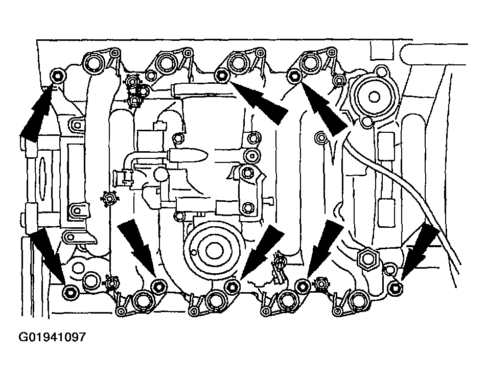
  2. Install the intake manifold and hand-tighten the bolts at the locations shown in illustration.
    Fig 2: Identifying Intake Manifold Bolts
    G01941097Courtesy of FORD MOTOR CO.
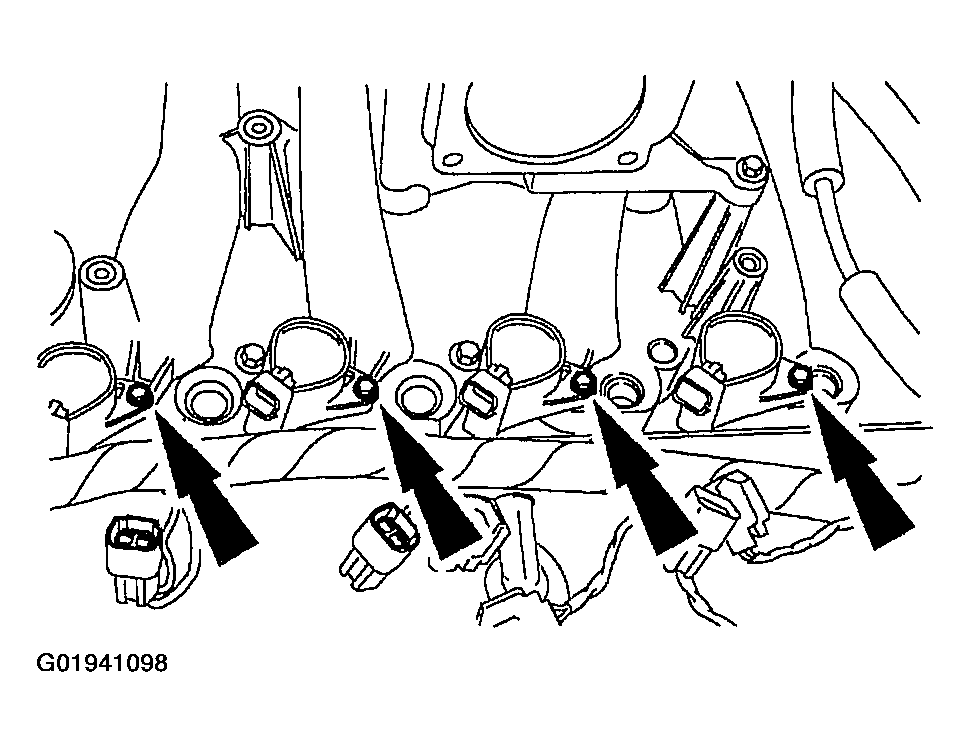
  3. Install the eight ignition coils and tighten the eight bolts.
    Fig 3: Identifying Ignition Coil Bolts
    G01941098Courtesy of FORD MOTOR CO.
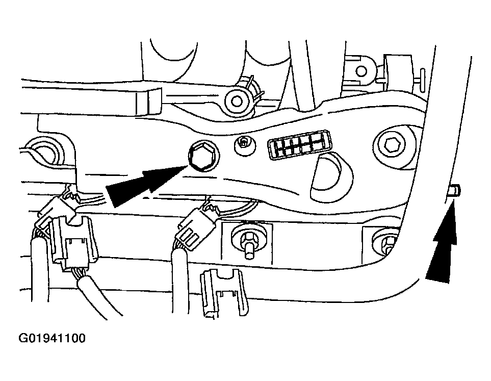
  4. Install the crash bracket and loosely install the bolt and the stud.
    Fig 4: Identifying Crash Bracket Bolt & Stud
    G01941100Courtesy of FORD MOTOR CO.
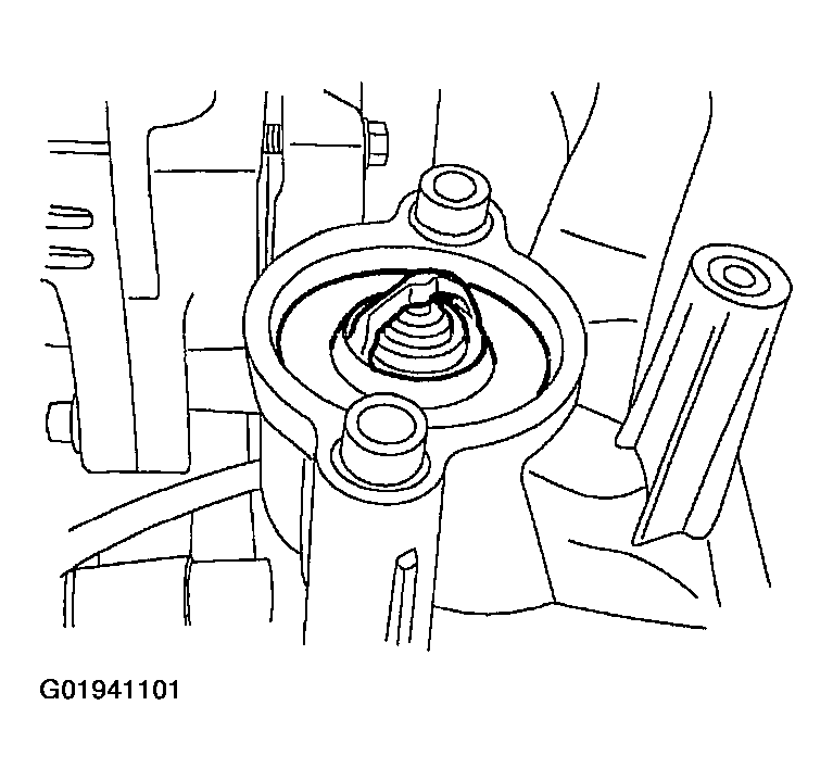
  5. Install the water thermostat.
    Fig 5: Identifying Water Thermostat
    G01941101Courtesy of FORD MOTOR CO.
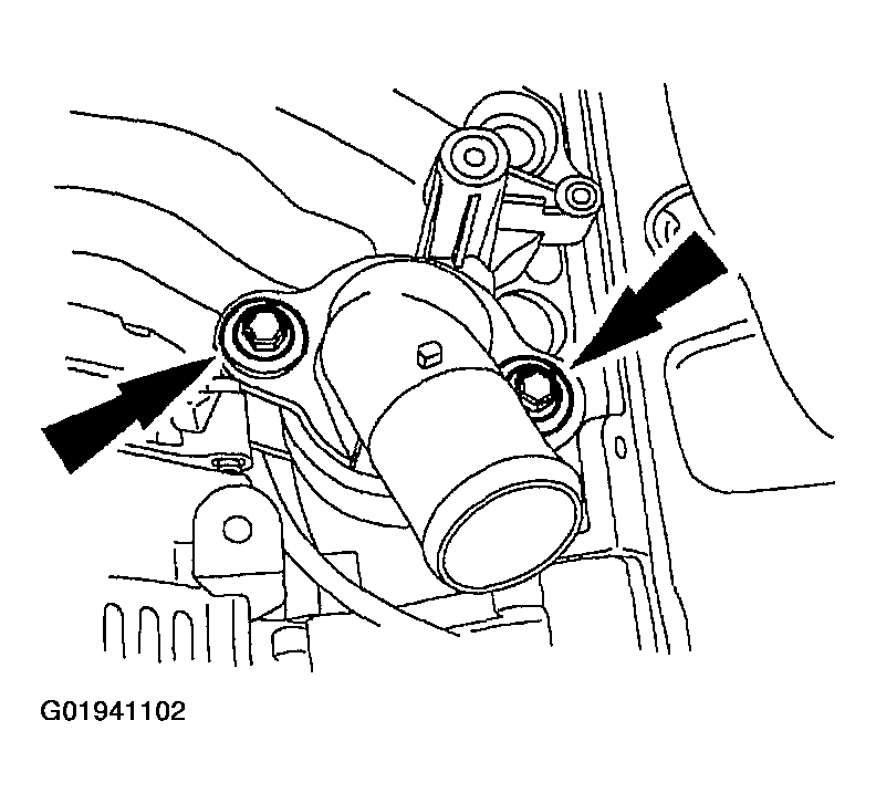
  6. Install the water outlet adapter and loosely install the bolts.
    Fig 6: Identifying Water Outlet Adapter Bolts
    G01941102Courtesy of FORD MOTOR CO.
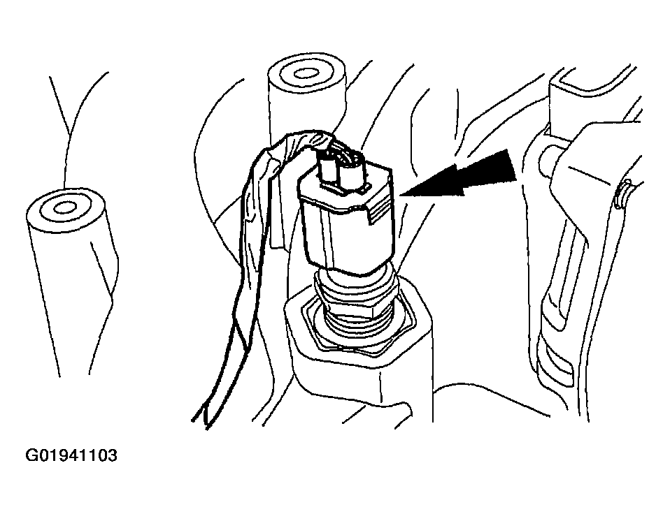
  7. Connect the coolant sensor connector.
    Fig 7: Identifying Coolant Sensor Connector
    G01941103Courtesy of FORD MOTOR CO.
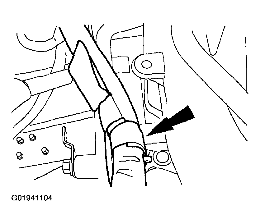
  8. Connect the fuel charging wiring harness position retainer to rear of the intake manifold.
    Fig 8: Identifying Fuel Charging Wiring Harness Position Retainer
    G01941104Courtesy of FORD MOTOR CO.
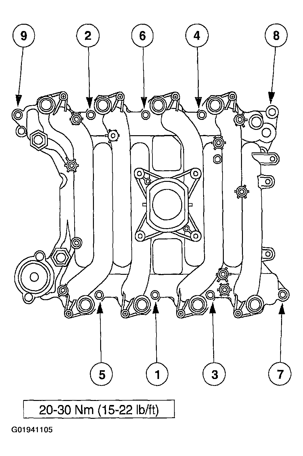
  9. Tighten the bolts in the sequence shown in illustration.
    Fig 9: Identifying Intake Manifold Tightening Sequence
    G01941105Courtesy of FORD MOTOR CO.
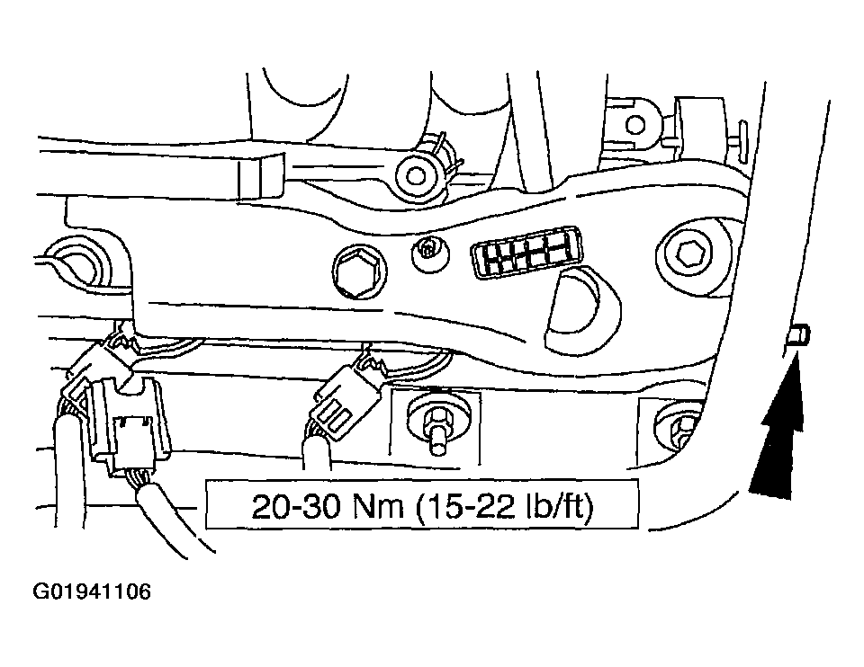
  10. Tighten the stud.
    Fig 10: Tightening Stud
    G01941106Courtesy of FORD MOTOR CO.
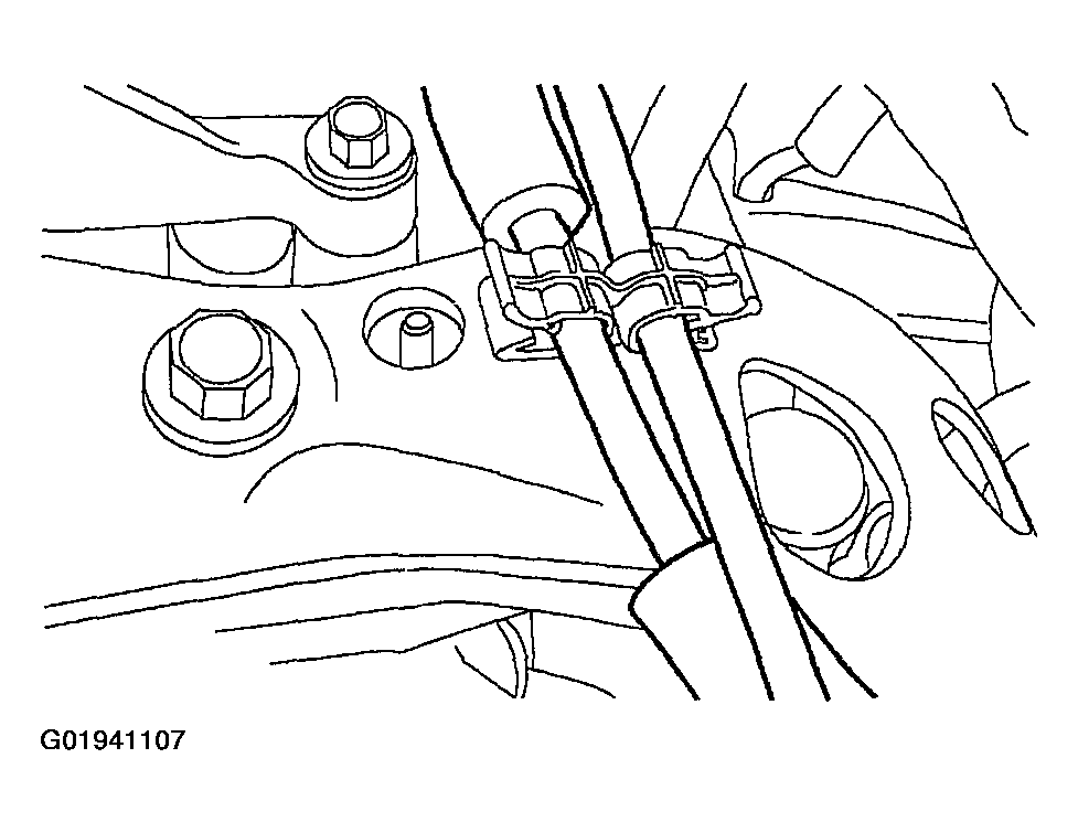
  11. Install the cables to the crash bracket.
    Fig 11: Identifying Crash Bracket & Cables
    G01941107Courtesy of FORD MOTOR CO.
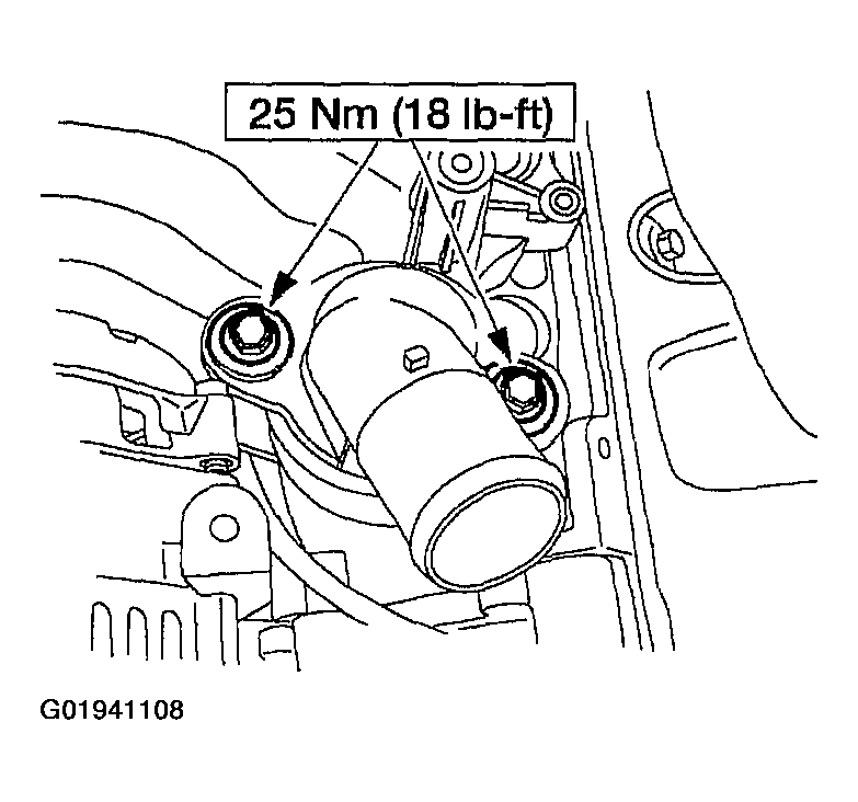
  12. Tighten the bolts.
    Fig 12: Tightening Water Outlet Adapter Bolts
    G01941108Courtesy of FORD MOTOR CO.
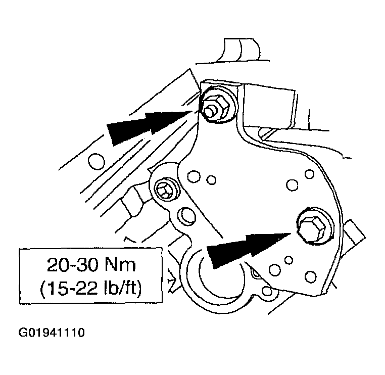
  13. Install the wiring bracket.
    • Position the bracket.
    • Install the nut and the bolt.
    • Attach the wiring connectors to the wiring bracket.
    • Connect the LH heated oxygen sensor electrical connector.
    Fig 13: Installing Wiring Bracket
    G01941110Courtesy of FORD MOTOR CO.
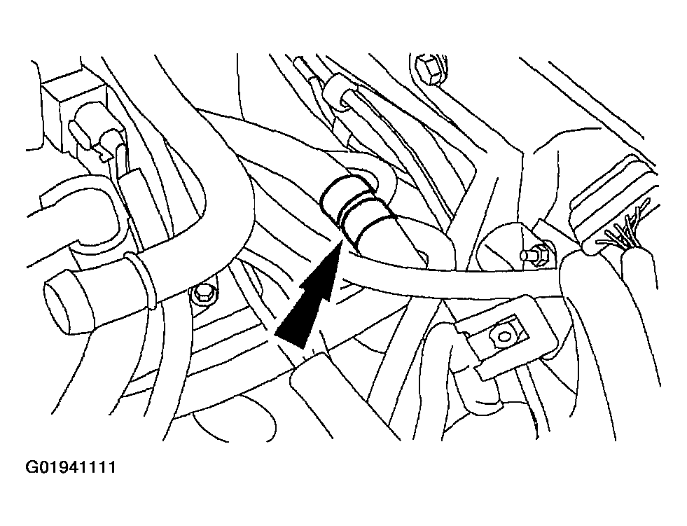
  14. Attach the fuel charging wiring harness pin-type retainer to the crash bracket.
    Fig 14: Identifying Fuel Charging Wiring Harness Pin-Type Retainer
    G01941111Courtesy of FORD MOTOR CO.
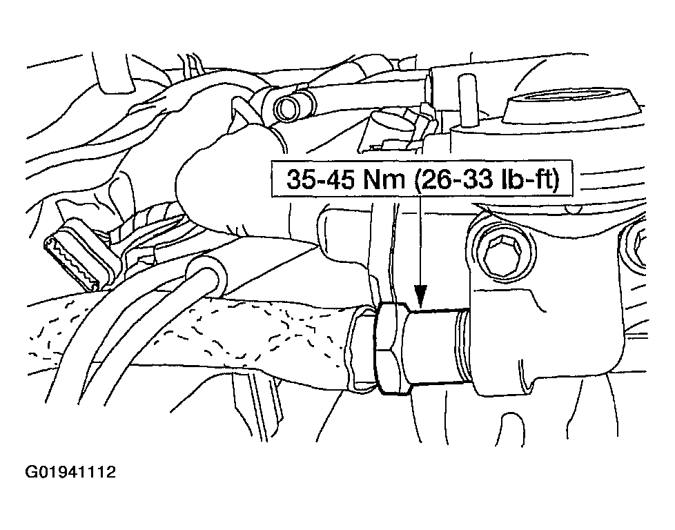
  15. Connect the EGR tube to the EGR valve.
    Fig 15: Tightening EGR Tube
    G01941112Courtesy of FORD MOTOR CO.
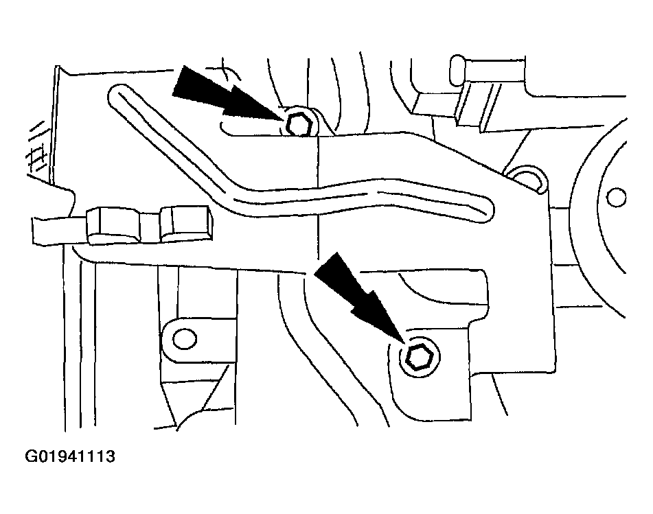
  16. Position the EGR tube heat shield and install the bolts.
    Fig 16: Identifying EGR Tube Heat Shield Bolts
    G01941113Courtesy of FORD MOTOR CO.
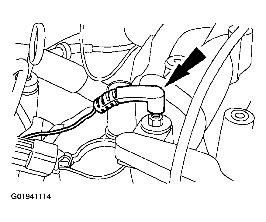
  17. Connect the ground connector to RH rear stud.
    Fig 17: Identifying RH Rear Stud Ground Connector
    G01941114Courtesy of FORD MOTOR CO.
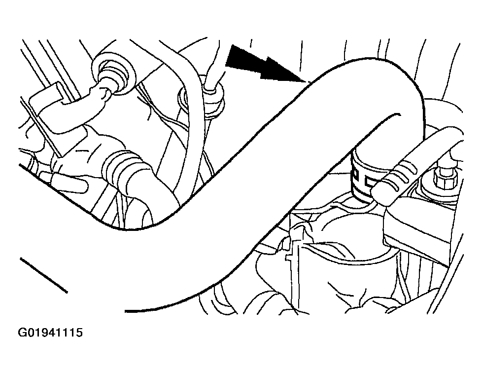
  18. Connect the heater water hose and position the clamp.
    Fig 18: Identifying Heater Water Hose
    G01941115Courtesy of FORD MOTOR CO.
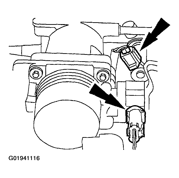
  19. Connect the electrical connector to the:
    • IAC control valve.
    • TP sensor.
    Fig 19: Identifying IAC Control Valve & TP Sensor Connectors
    G01941116Courtesy of FORD MOTOR CO.
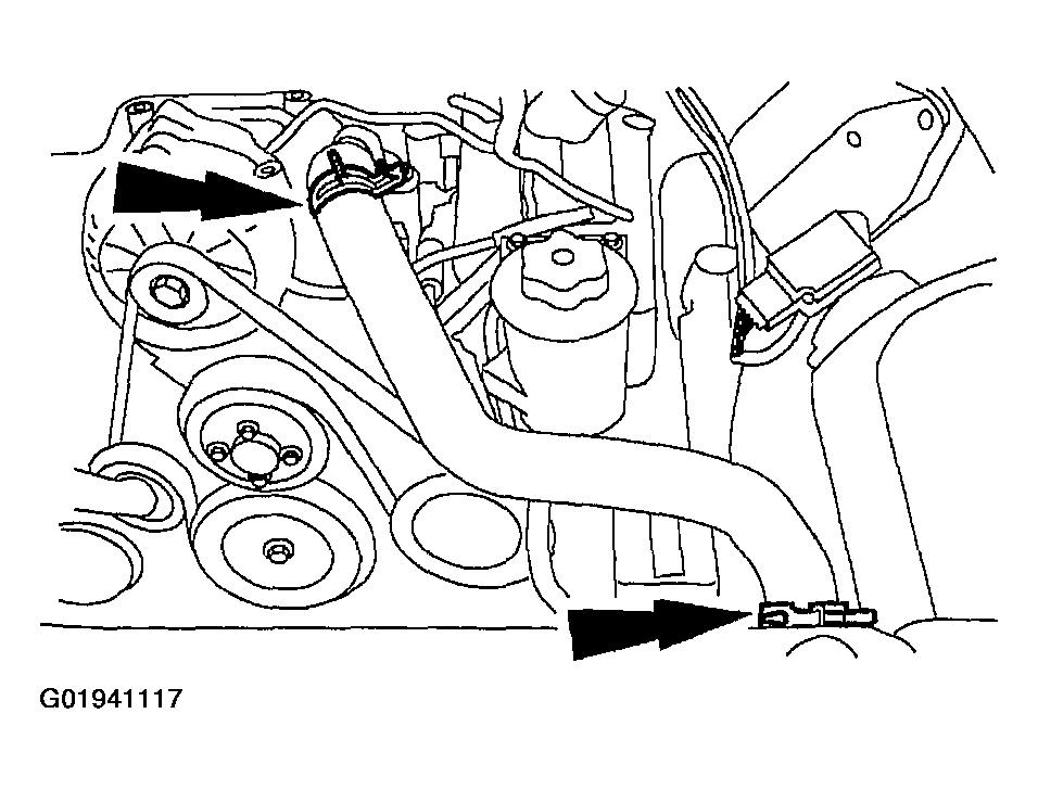
  20. Install the upper radiator hose.
    • Install the upper radiator hose.
    • Position the clamps.
    Fig 20: Identifying Upper Radiator Hose Clamps
    G01941117Courtesy of FORD MOTOR CO.
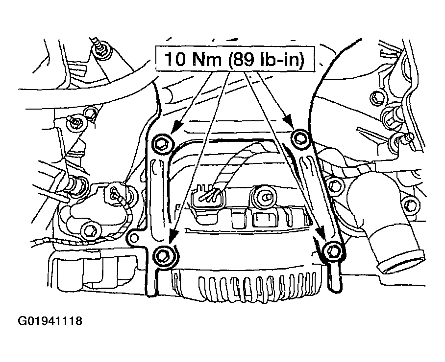
  21. Install the generator mounting bracket and the bolts.
    Fig 21: Tightening Generator Mounting Bracket Bolts
    G01941118Courtesy of FORD MOTOR CO.
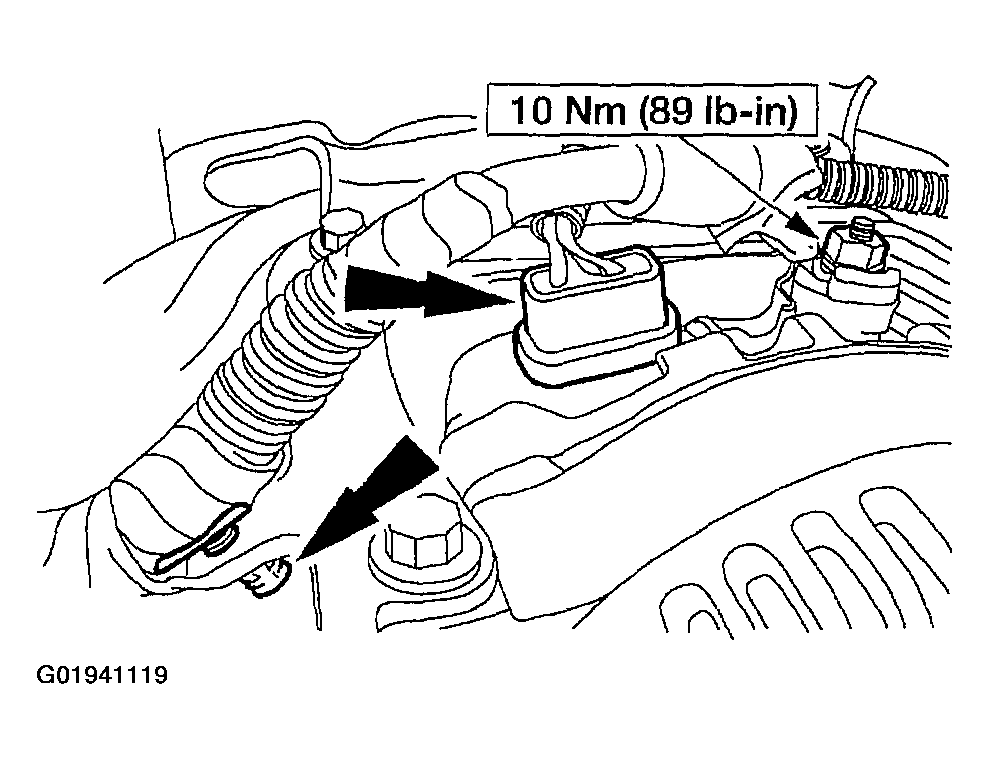
  22. Connect the generator electrical connector, the cable and the harness pin-type retainer.
    Fig 22: Identifying Generator Electrical Connector & Harness Pin-Type Retainer
    G01941119Courtesy of FORD MOTOR CO.
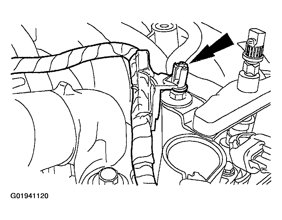
  23. Install the generator harness position retainer to LH front studs.
    Fig 23: Identifying Generator Harness Position Retainer
    G01941120Courtesy of FORD MOTOR CO.
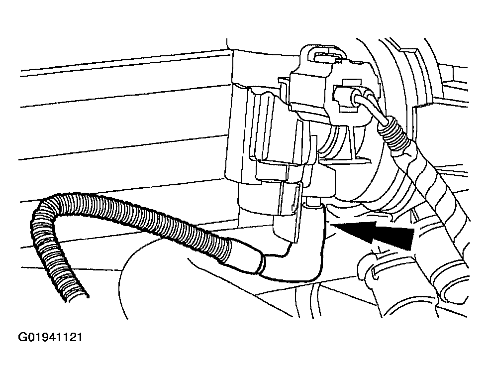
  24. Position the vacuum harness and connect the vacuum hose to the EVAP canister purge valve.
    Fig 24: Identifying EVAP Canister Purge Valve Vacuum Hose
    G01941121Courtesy of FORD MOTOR CO.
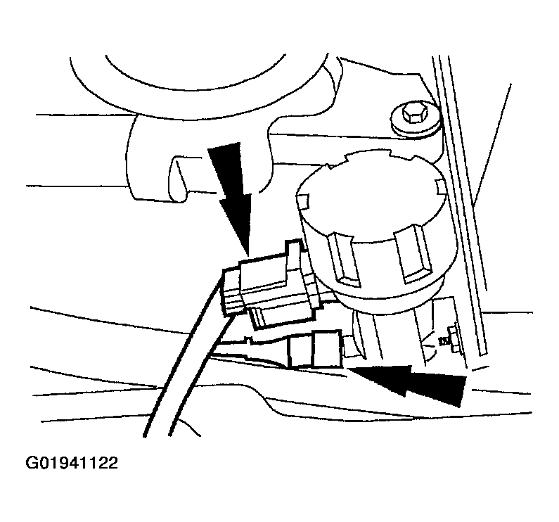
  25. Connect the electrical connector and the vacuum hoses to the EGR vacuum regulator solenoid.
    Fig 25: Identifying EGR Vacuum Regulator Solenoid Electrical Connector & Vacuum Hoses
    G01941122Courtesy of FORD MOTOR CO.
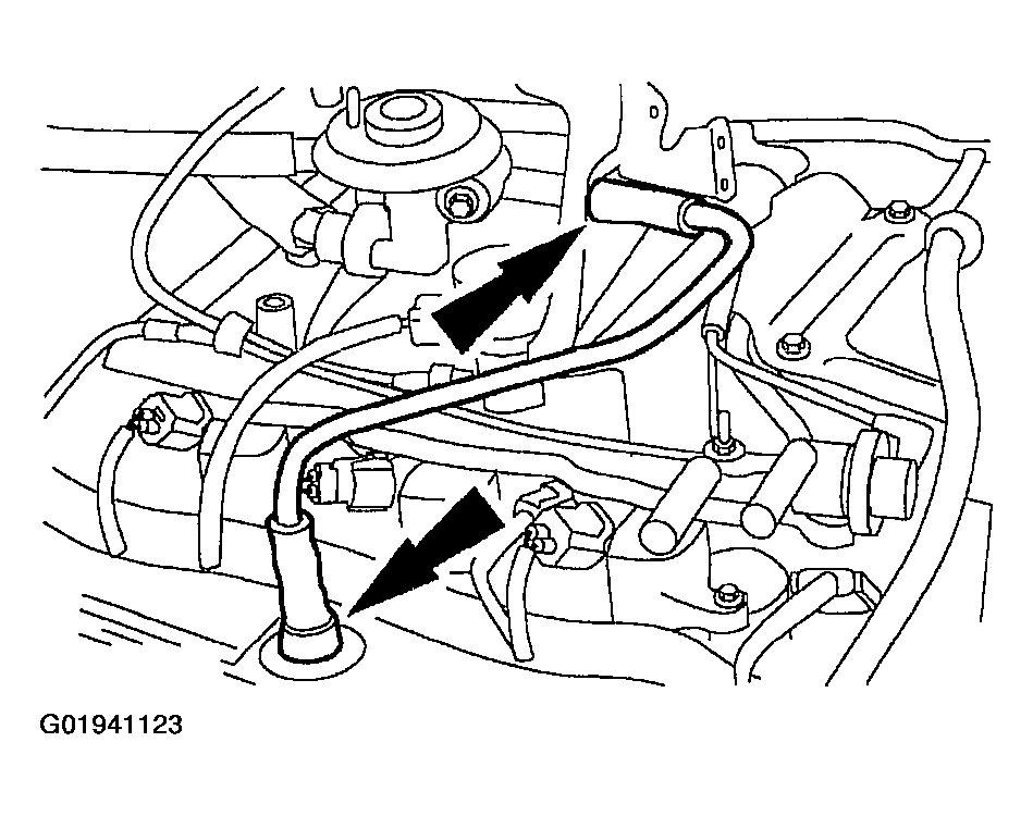
  26. Install and connect the PCV tube.
    Fig 26: Identifying PCV Tube
    G01941123Courtesy of FORD MOTOR CO.
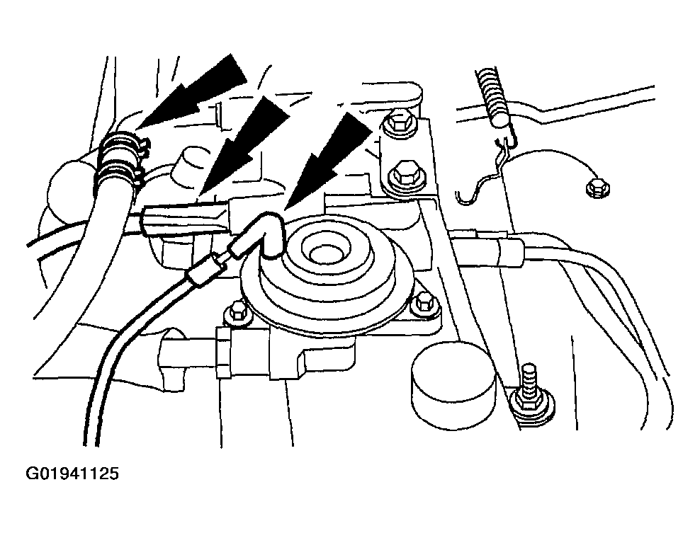
  27. Connect the vacuum hoses for the EVAP canister purge valve, the main chassis vacuum supply line and the EGR valve.
    Fig 27: Identifying EVAP Canister Purge Valve, Main Chassis Vacuum Supply Line & EGR Valve Vacuum Hoses
    G01941125Courtesy of FORD MOTOR CO.
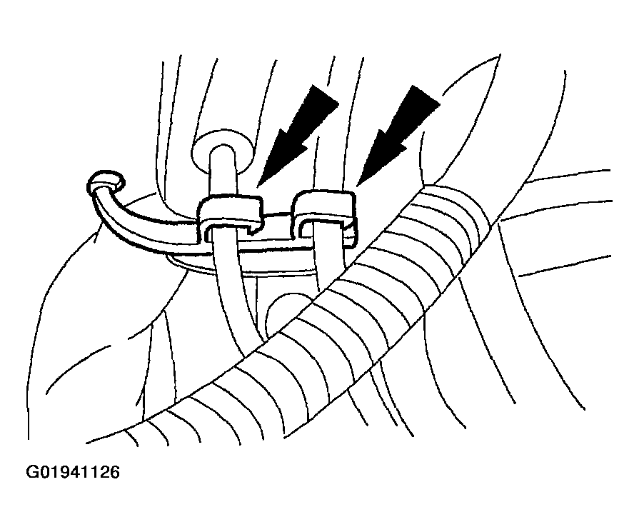
  28. Reposition and attach the cables to the EGR tube heat shield.
    Fig 28: Identifying EGR Tube Heat Shields
    G01941126Courtesy of FORD MOTOR CO.
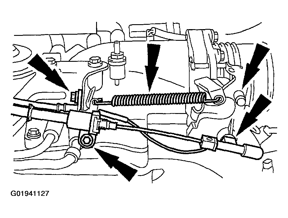
  29. Connect the accelerator cable and the speed control actuator cable, and the throttle return spring.
    Fig 29: Identifying Accelerator Cable, Speed Control Actuator Cable & Throttle Return Spring
    G01941127Courtesy of FORD MOTOR CO.
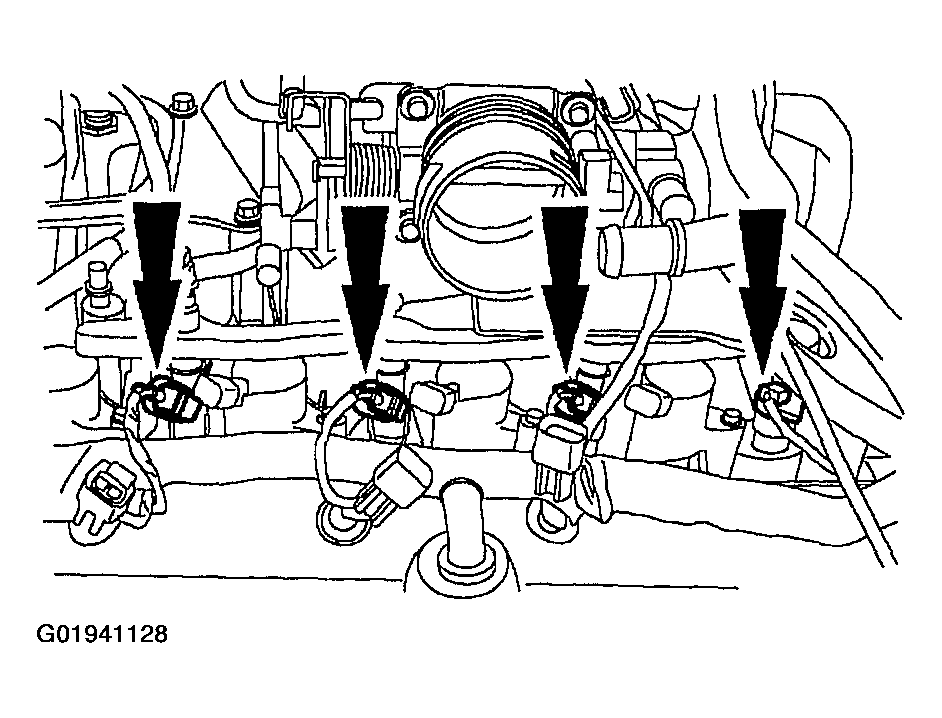
  30. Connect the fuel charging wiring electrical connectors to the eight fuel injectors.
    Fig 30: Identifying Fuel Charging Wiring Electrical Connectors & Fuel Injectors
    G01941128Courtesy of FORD MOTOR CO.
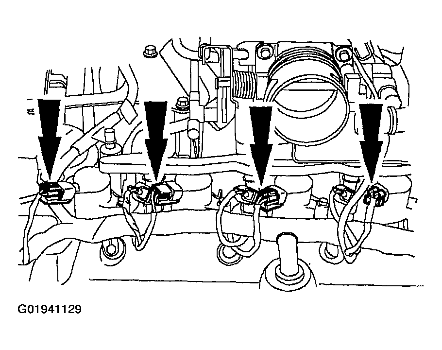
  31. Connect the fuel charging wiring electrical connectors to the eight ignition coils.
    Fig 31: Identifying Fuel Charging Wiring Electrical Connectors & Ignition Coils
    G01941129Courtesy of FORD MOTOR CO.
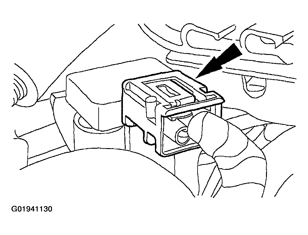
  32. Connect the differential pressure feedback EGR electrical connectors.
    Fig 32: Identifying Differential Pressure Feedback EGR Electrical Connectors
    G01941130Courtesy of FORD MOTOR CO.
  33. Raise the vehicle.
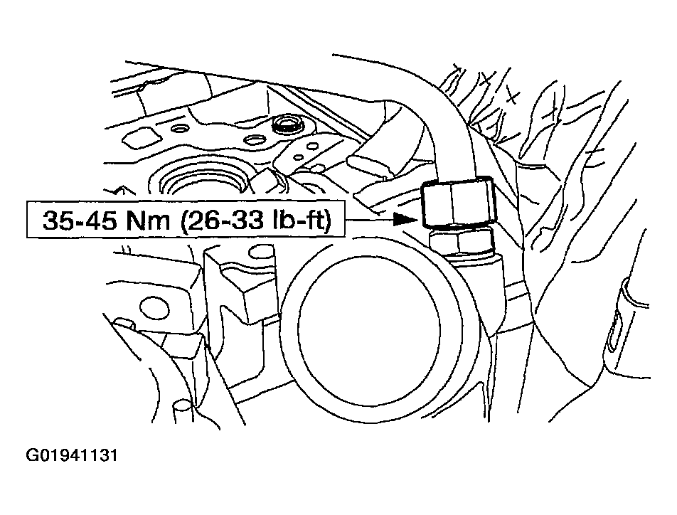
  34. Connect the EGR tube to the exhaust manifold.
    Fig 33: Tightening EGR Tube
    G01941131Courtesy of FORD MOTOR CO.
  35. Lower the vehicle.
  36. Install the drive belt.
  37. Install the wiper mounting arm and pivot shaft. For additional information, refer to MOUNTING ARM AND PIVOT SHAFT .
  38. Connect the fuel line. For additional information, refer to FUEL SYSTEMS .
  39. Install the air cleaner outlet tube.
  40. Connect the battery ground cable.
  41. Check the engine oil.
  42. Fill the engine cooling system.