LEMON Manuals: Even more car manuals for everyone: 1960-2025
Home >> Ford >> 2002 >> Crown Victoria Base, 4.6 9 >> Repair and Diagnosis >> Engine Mechanical >> Mechanical >> Engine - 4.6L >> In-Vehicle Repair >> Valve Cover RH >> Removal & Installation

Removal & Installation

  1. Drain cooling system.
  2. Raise and support the vehicle.
  3. Disconnect the crankshaft position (CKP) sensor electrical connector.
    Fig 1: Identifying Crankshaft Position (CKP) Sensor Electrical Connector
    G01941218Courtesy of FORD MOTOR CO.
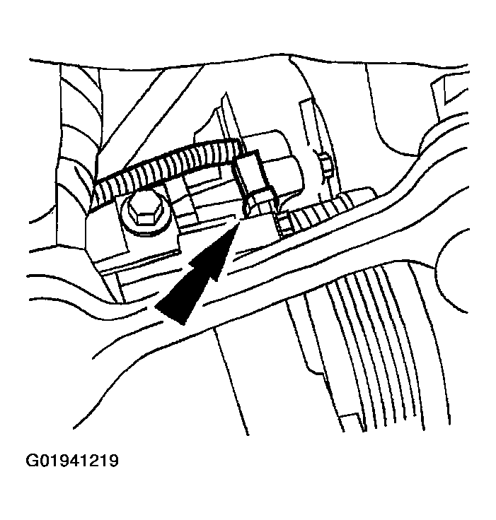
  4. Disconnect the A/C compressor electrical connector.
    Fig 2: Identifying A/C Compressor Electrical Connector
    G01941219Courtesy of FORD MOTOR CO.
  5. Lower the vehicle.
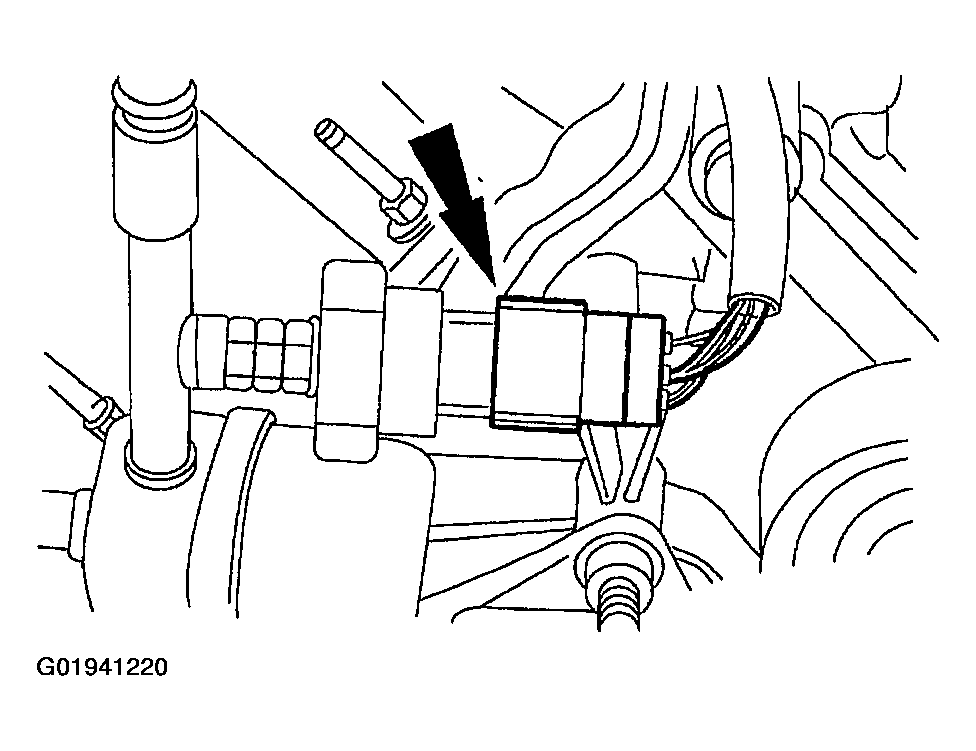
  6. Disconnect the A/C cycling switch connector.
    Fig 3: Identifying A/C Cycling Switch Connector
    G01941220Courtesy of FORD MOTOR CO.
  7. Disconnect the fuel lines. For additional information, refer to FUEL SYSTEM - GENERAL INFORMATION or FUEL SYSTEM - GENERAL INFORMATION - NATURAL GAS .
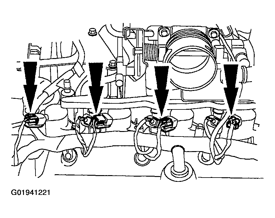
  8. Disconnect the ignition coils electrical connectors.
    Fig 4: Identifying Ignition Coil Electrical Connectors
    G01941221Courtesy of FORD MOTOR CO.
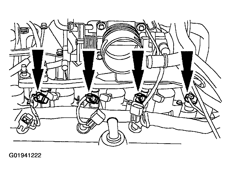
  9. Disconnect the fuel injector electrical connectors.
    Fig 5: Identifying Fuel Injector Electrical Connectors
    G01941222Courtesy of FORD MOTOR CO.
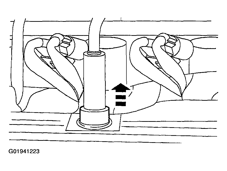
  10. Remove the positive crankcase ventilation (PCV) tube and position out of the way.
    Fig 6: Removing Positive Crankcase Ventilation (PCV) Tube
    G01941223Courtesy of FORD MOTOR CO.
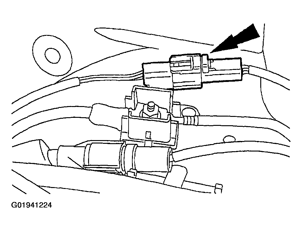
  11. Disconnect the electrical connector.
    Fig 7: Identifying Electrical Connector
    G01941224Courtesy of FORD MOTOR CO.
  12. Remove the evaporative emission (EVAP) canister purge valve. For additional information, refer to EVAPORATIVE SYSTEM PURGE VALVE .
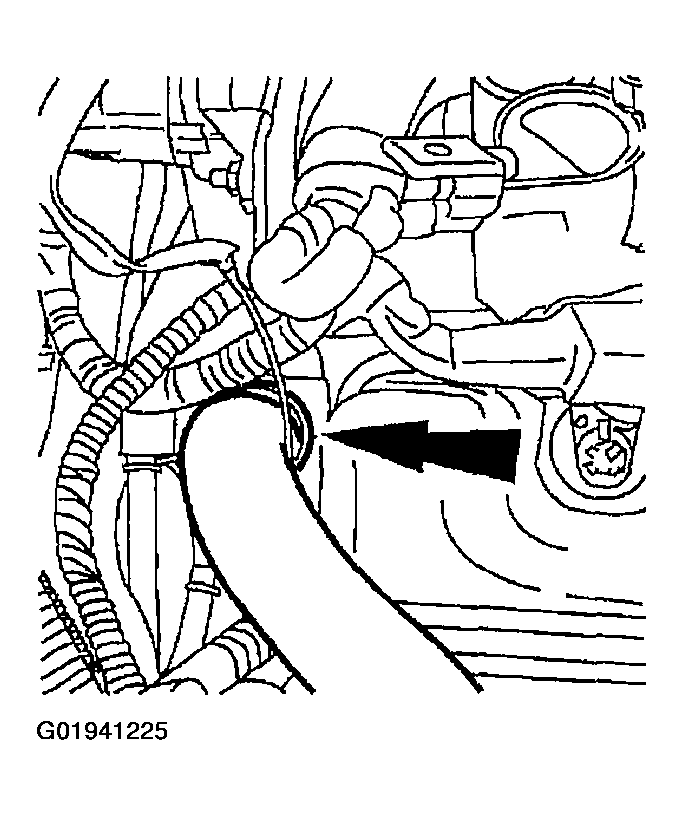
  13. Reposition the hold-down clamp and remove the hose from the bypass tube.
    Fig 8: Identifying Bypass Tube
    G01941225Courtesy of FORD MOTOR CO.
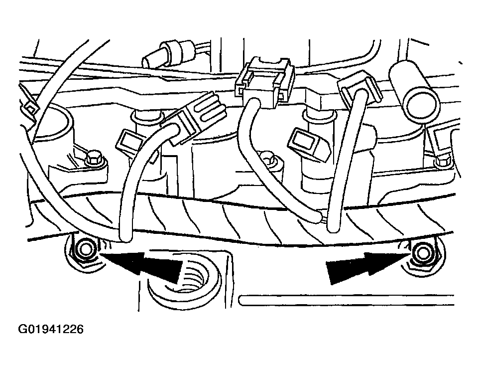
  14. NOTE: The valve cover harness retaining studs positions 2 and 3 retain the fuel charging wiring.
    Fig 9: Disconnecting Harness From Valve Cover
    G01941226Courtesy of FORD MOTOR CO.
  15. Disconnect the harness from the valve cover and position out of the way.
  16. Remove the LH engine mount. For additional information, see ENGINE MOUNT - LH .
  17. Lower engine.
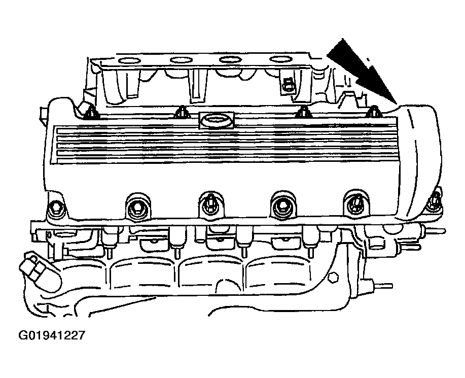
  18. Remove the studs, the bolts and the valve cover.
    Fig 10: Identifying Valve Cover
    G01941227Courtesy of FORD MOTOR CO.
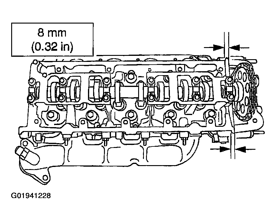
  19. To install, reverse the removal procedure.
    • Apply sealant in the location shown.
    Fig 11: Identifying Sealant Location
    G01941228Courtesy of FORD MOTOR CO.
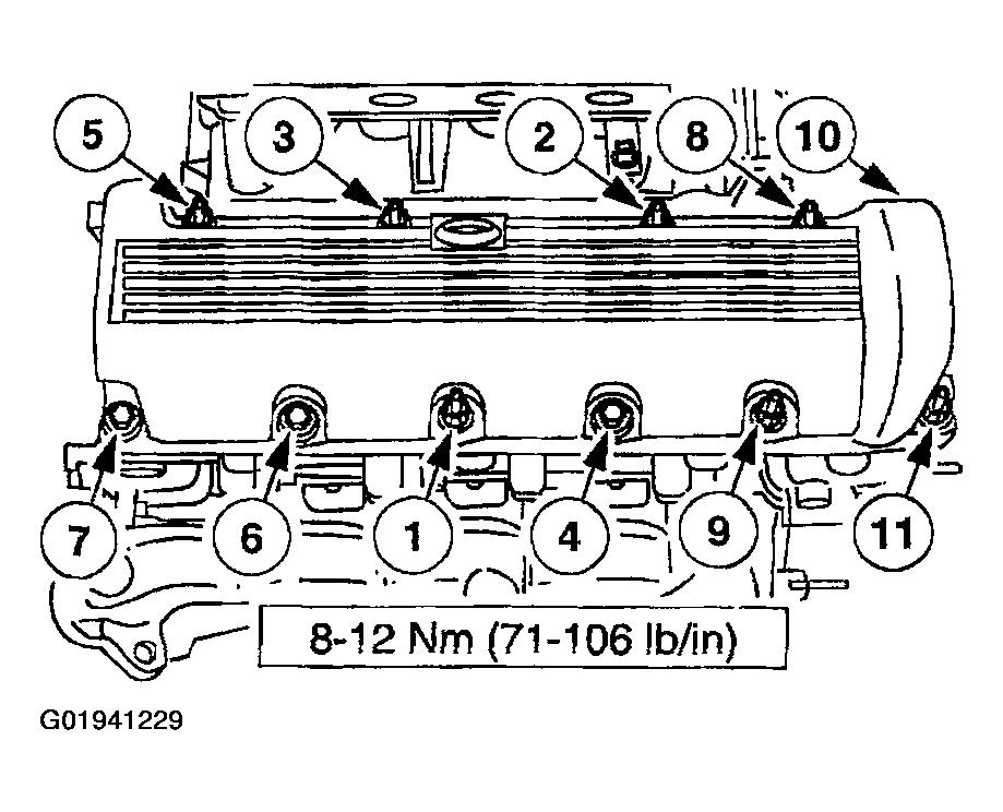
  20. Tighten the bolts in the sequence shown.
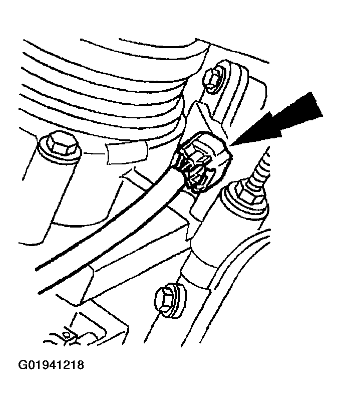
    Fig 12: Identifying Valve Cover Bolt Tightening Sequence
    G01941229Courtesy of FORD MOTOR CO.