Removal & Installation
- Raise and support the vehicle.
- Disconnect the oil pressure sensor electrical connector, the power steering pressure sensor electrical connector and the harness position retainer.
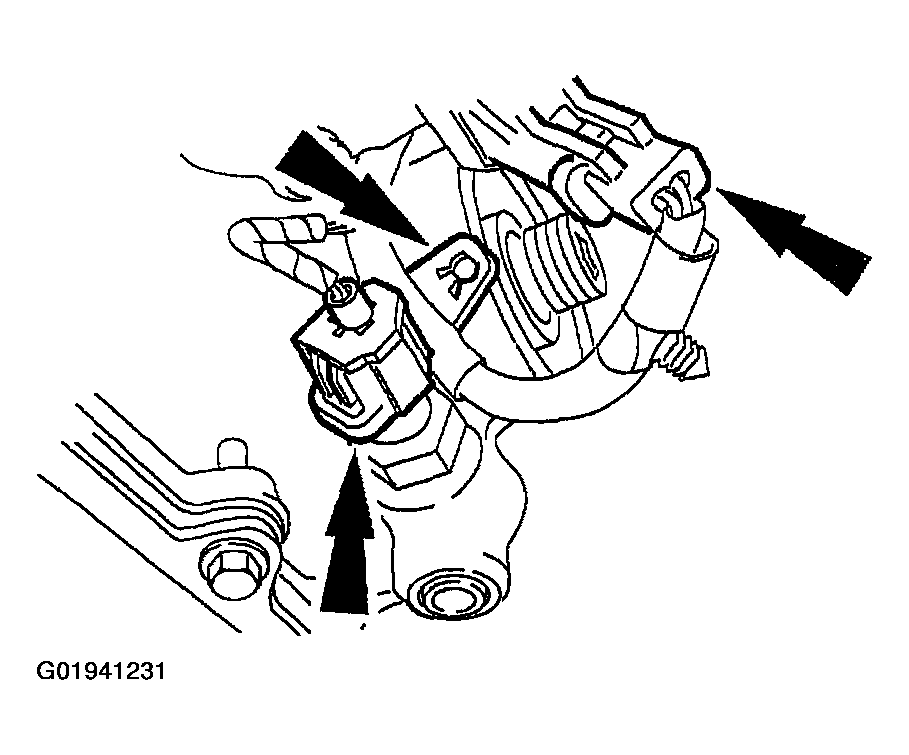 Courtesy of FORD MOTOR CO.
- Lower the vehicle.
- Disconnect the cylinder head temperature (CHT) sensor jumper wire connector.
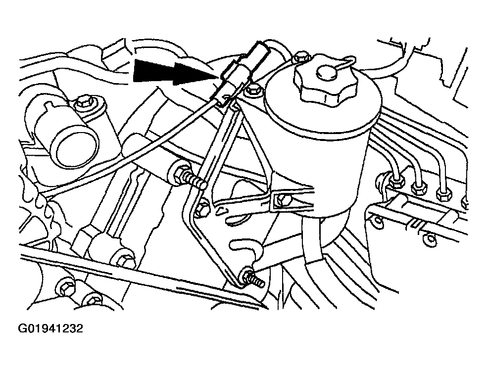 Courtesy of FORD MOTOR CO.
- Remove the bolt and the two studs and position the bracket out of the way.
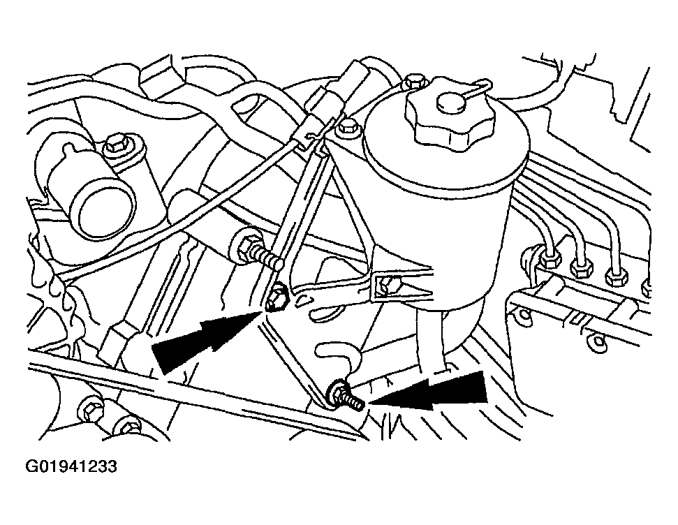 Courtesy of FORD MOTOR CO.
- Disconnect the camshaft position (CMP) sensor electrical connector.
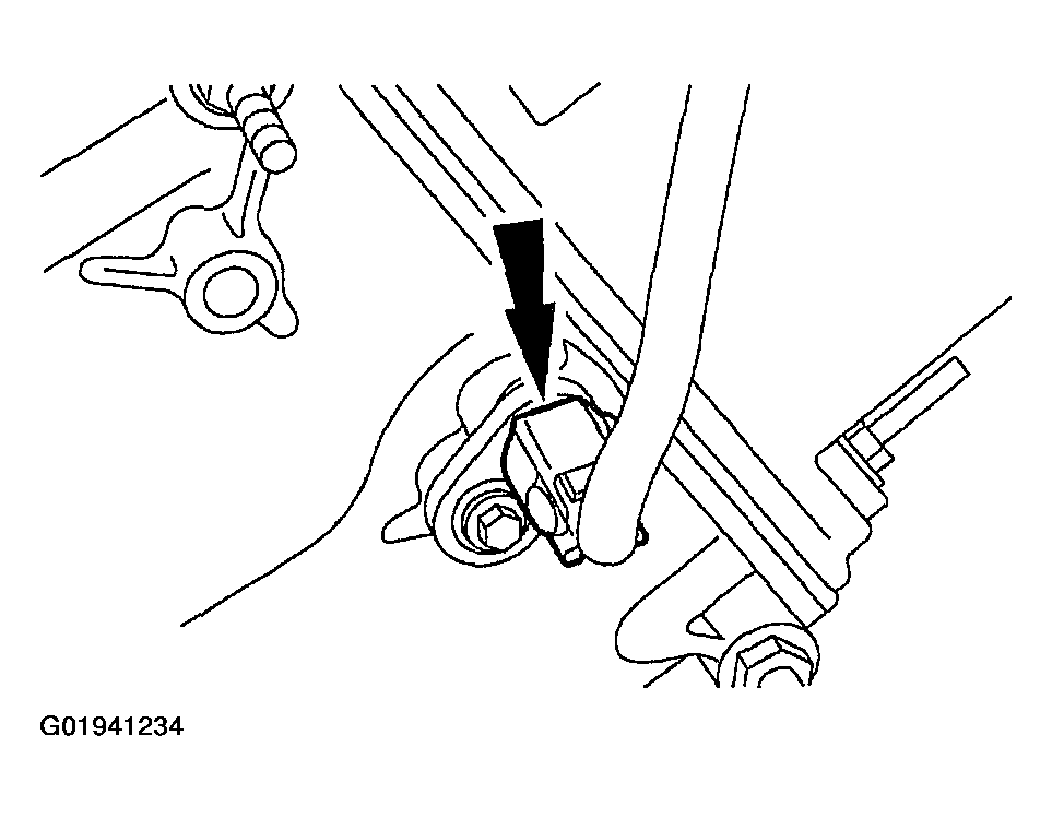 Courtesy of FORD MOTOR CO.
- Disconnect the fuel charging wiring electrical connectors from the coils and the fuel injectors.
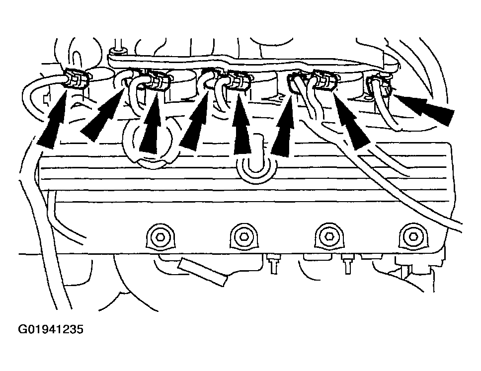 Courtesy of FORD MOTOR CO.
- Remove the wiper and cowl. For additional information, refer to
WIPER MOTOR
.
- Disconnect the:
- 42-pin connector.
- 16-pin connector.
- Transmission electrical connector.
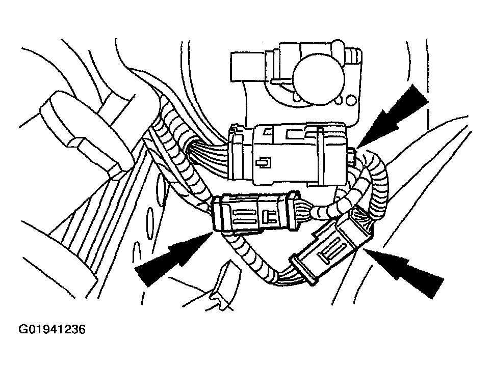 Courtesy of FORD MOTOR CO.
- Remove the six bolts and five studs and remove the valve cover.
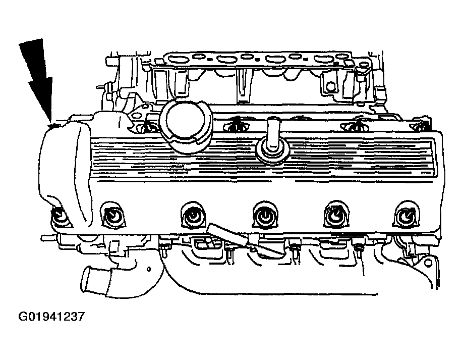 Courtesy of FORD MOTOR CO.
- To install, reverse the removal procedure.
- Apply sealant in the locations shown.
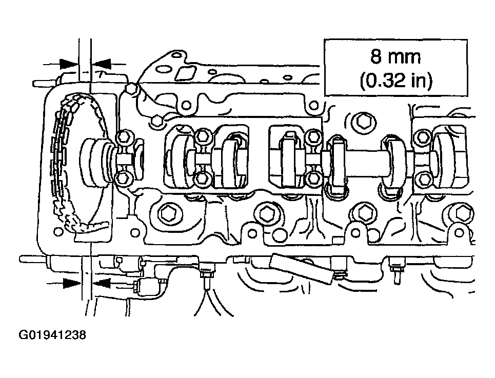 Courtesy of FORD MOTOR CO.
- Tighten the bolts and studs in the sequence shown.
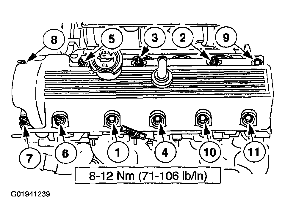 Courtesy of FORD MOTOR CO.