Timing Drive Components: Installation
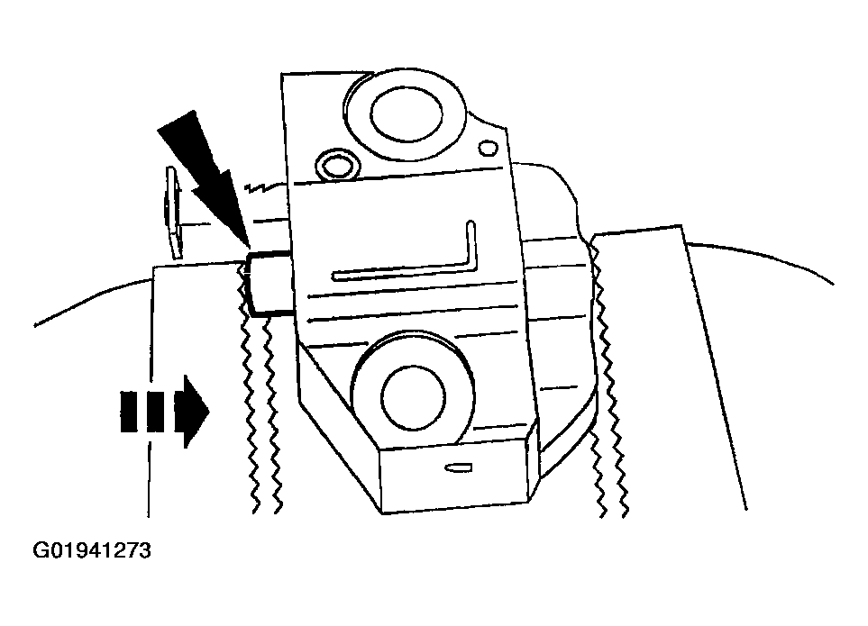
- Compress the tensioner plunger, using an edge of a vise.
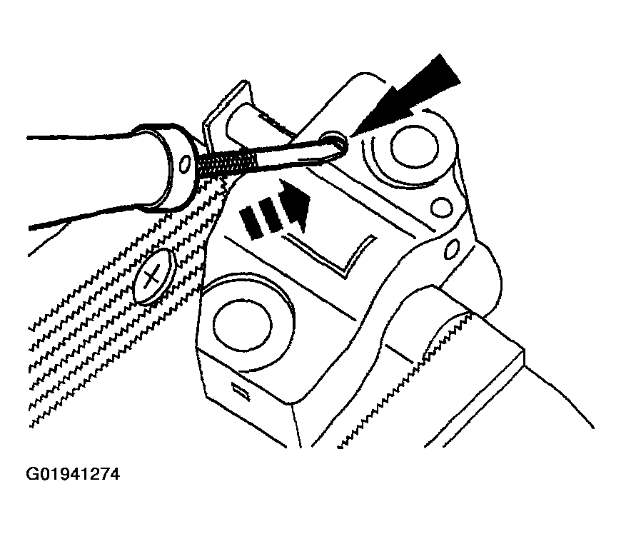
- Using a small screwdriver or pick, push back and hold the ratchet mechanism.
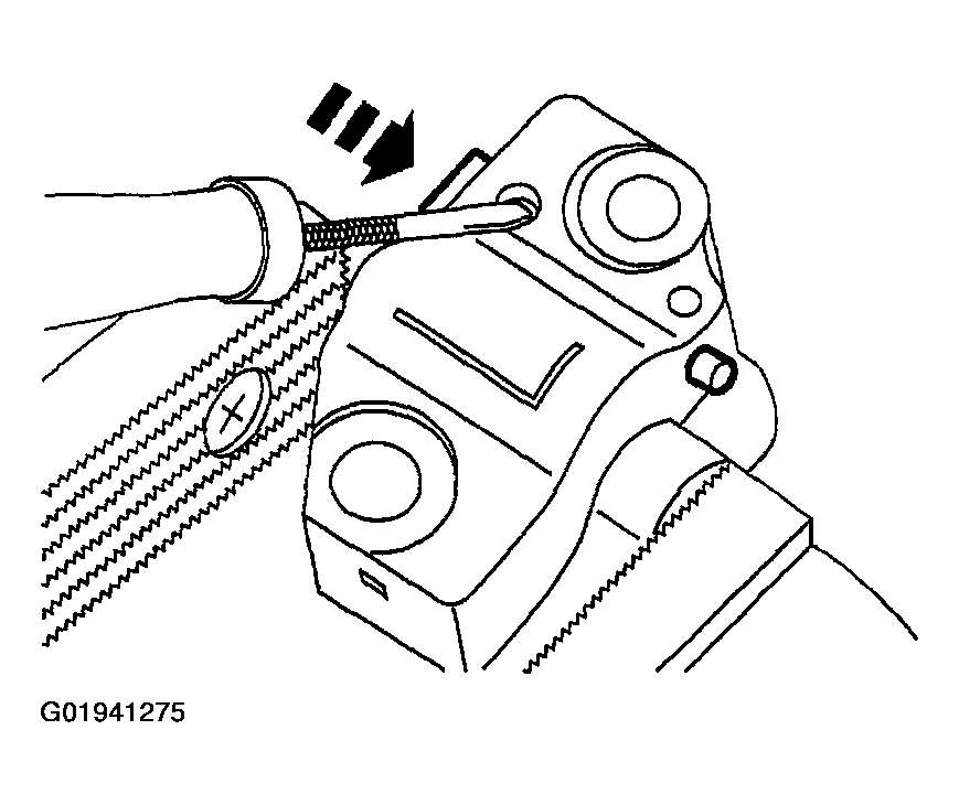
- While holding the ratchet mechanism, push the ratchet arm back into the tensioner housing.
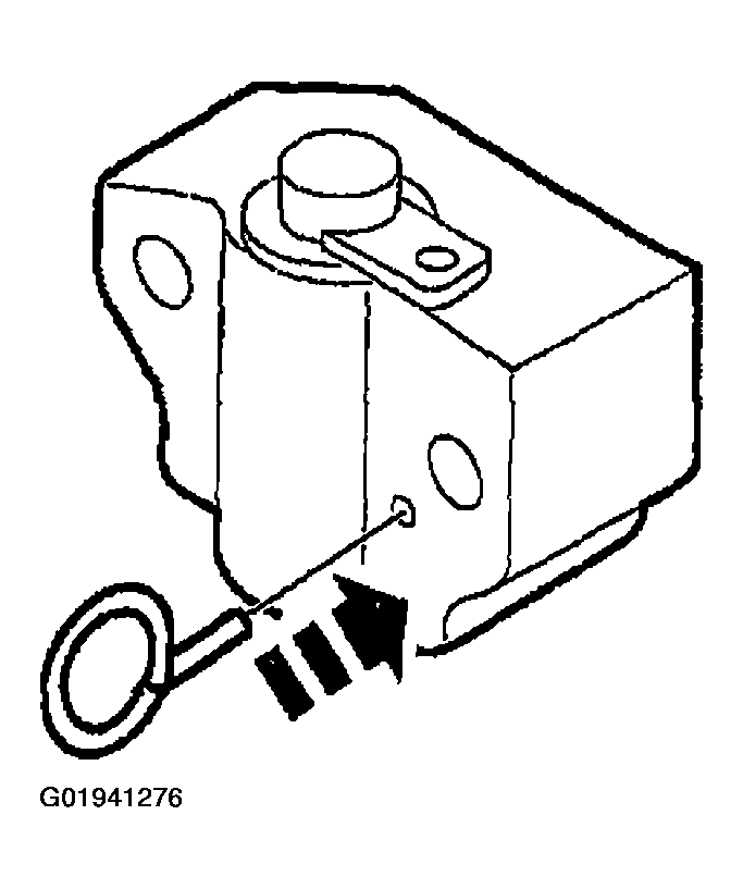
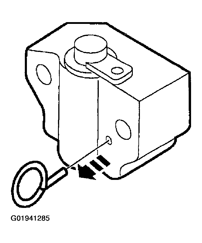
- Install a paper clip into the hole in the tensioner housing to hold the ratchet assembly and plunger in during installation.
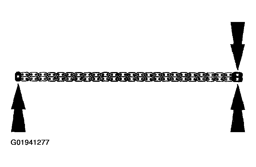
- If the copper links are not visible, mark two links on one end and one link on the other end, and use as timing marks.
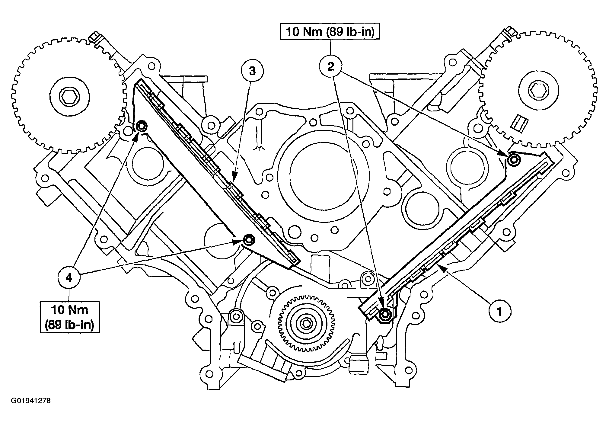
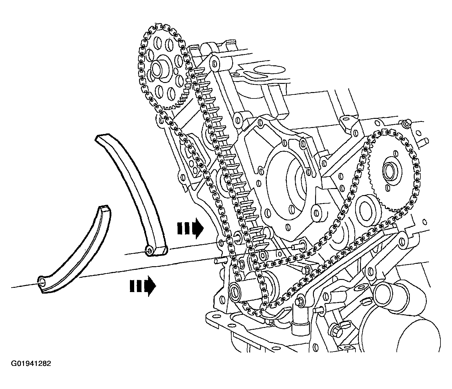
- Install the timing chain guide.
- Position LH timing chain guide.
- Install and tighten the bolts.
- Position the RH timing chain guide.
- Install and tighten the RH bolts.
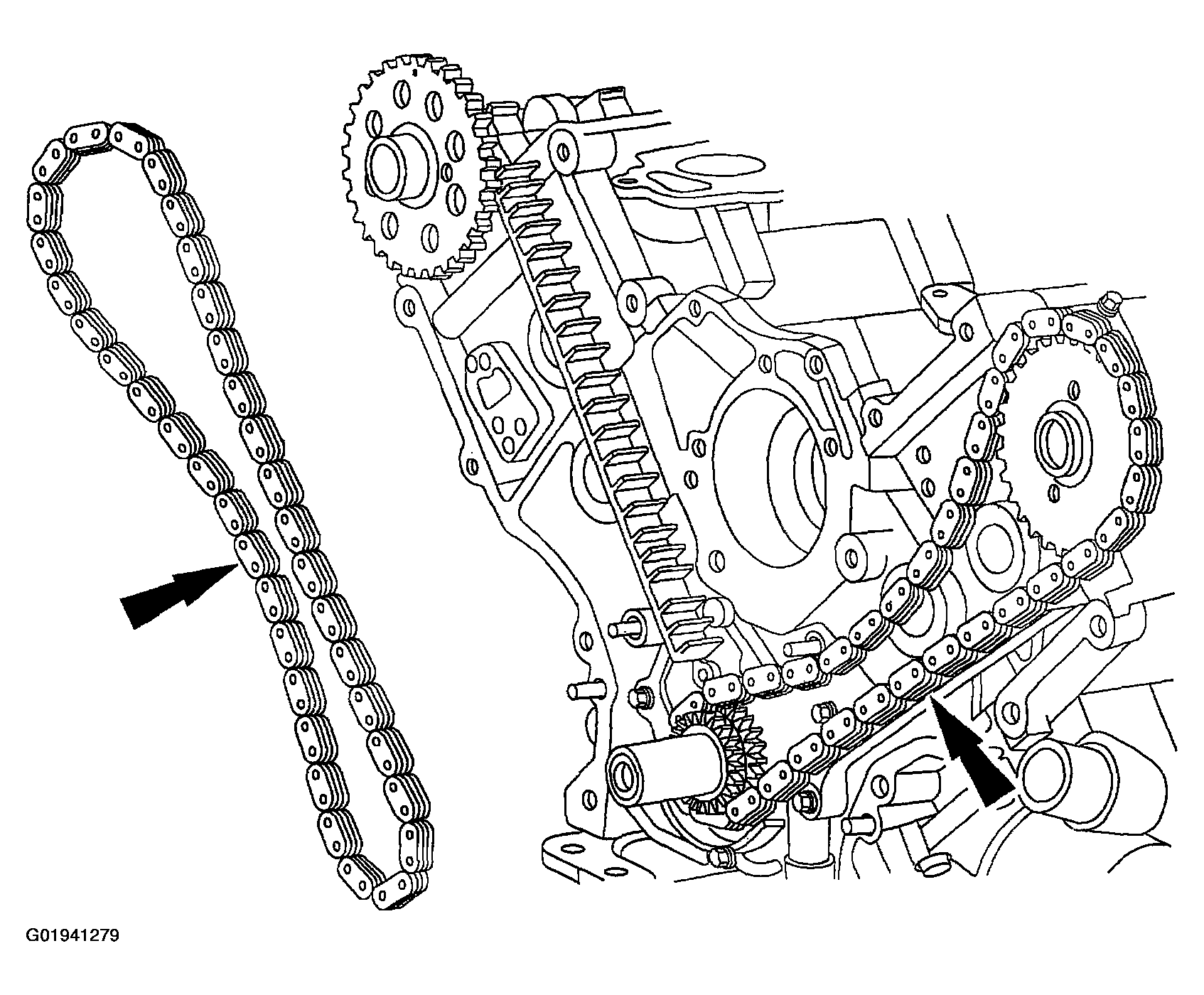
- Install the timing chain and the crankshaft sprocket.
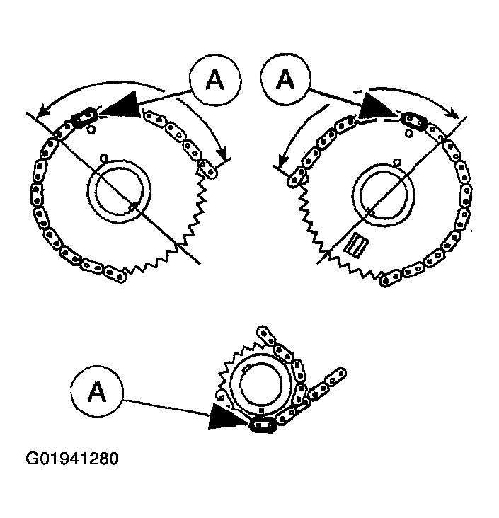
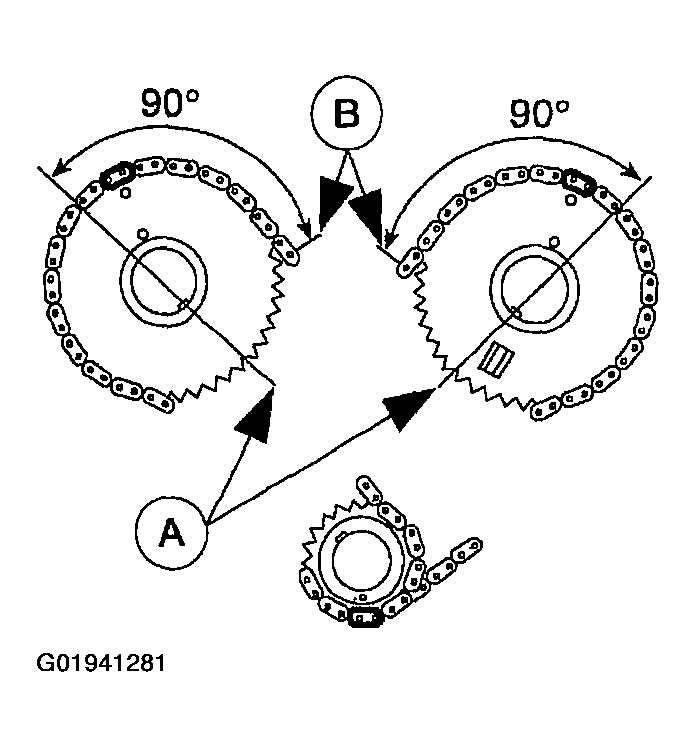
- Slide the crankshaft sprocket onto the crankshaft, aligning the copper links on the timing chains with the dot on the crankshaft sprocket.
- Position the timing chains over the camshaft sprockets, aligning the copper links with the dots on the camshaft sprockets.
- Make sure that the (A) copper marks on the timing chain/belt are lined up with the corresponding dots on the crankshaft sprockets and the camshaft sprocket.
- Make sure that the (A) camshaft sprocket keyway is 90 degrees from the (B) valve cover mounting surface.
- Position the LH and RH timing chain tensioner arms on the dowel pins.
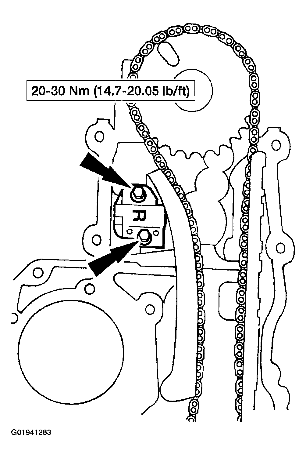
- Position the RH timing chain tensioner and install the bolts.
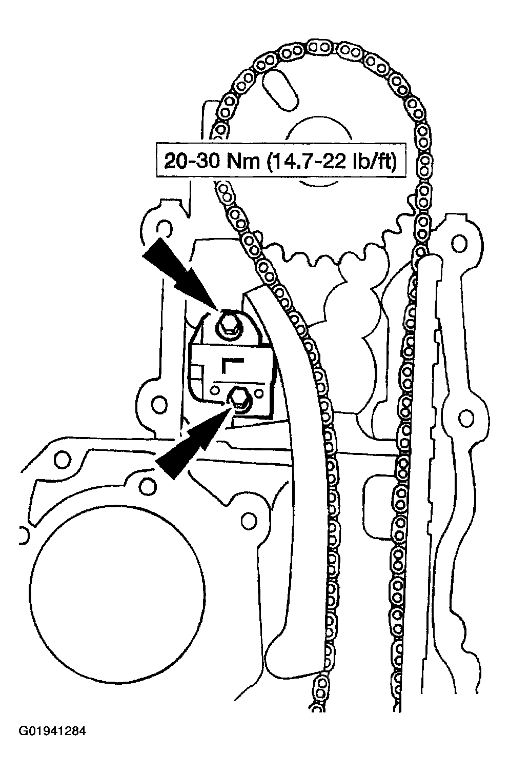
- Position the LH timing chain tensioner and install the bolts.
- Remove both the RH and LH retaining pins from the timing chain tensioner.
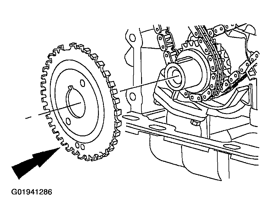
- Install the crankshaft sensor ring on the crankshaft sprocket.
- Install the engine front cover. For additional information, refer to ENGINE FRONT COVER .
- Install the roller followers. For additional information, refer to CAMSHAFT ROLLER FOLLOWER .
CAUTION:
The timing chain procedures must be followed exactly or damage to valves and pistons will result.
CAUTION:
Do not compress the ratchet assembly. This will damage the ratchet assembly.