Test A: One Door Lock Inoperative
NOTE:
Perform all voltage and resistance tests using an Digital Volt-Ohm Meter (DVOM) with a minimum 10-megohm input impedance, unless stated otherwise in test procedure. Use ohmmeter to isolate wiring harness shorts or opens.
- Manually operate inoperative door lock and check for binding or sticking lock. If door lock is not binding or sticking, go to next step. If door lock is binding or sticking, repair as necessary. After repair, test system for normal operation.
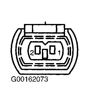
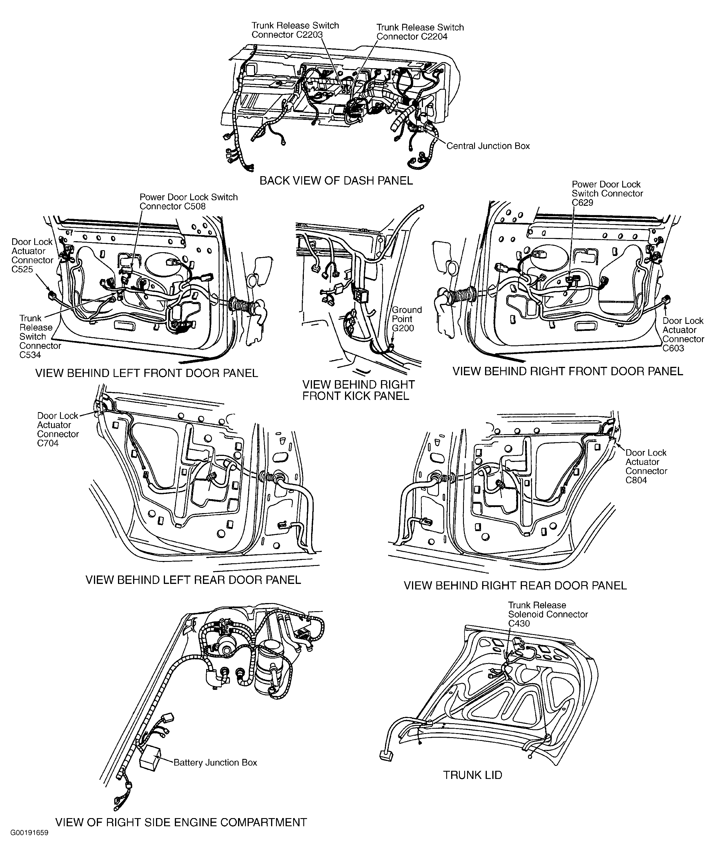
- Turn ignition switch to LOCK position. Remove door trim panel. See DOOR TRIM PANEL under REMOVAL & INSTALLATION. Disconnect inoperative door lock actuator 2-pin harness connector, located behind door trim panel. See Figure. While pressing door lock switch to lock, measure voltage between ground and door lock actuator harness connector terminal No. 1 (Pink/Orange wire). See Fig 1. See WIRING DIAGRAMS . If voltage is greater than 10 volts, go to next step. If voltage is 10 volts or less, repair open circuit in Pink/Orange wire between inoperative door lock actuator and passenger door lock switch. After repair, test system for normal operation.
- While pressing door lock switch to unlock, measure voltage between ground and inoperative door lock actuator harness connector terminal No. 2 (Pink/Black wire). See Fig 1. See WIRING DIAGRAMS . If voltage is greater than 10 volts, go to next step. If voltage is 10 volts or less, repair open circuit in Pink/Black wire between inoperative door lock actuator and Lighting Control Module (LCM) located behind driver's door trim panel. See Figure. After repair, test system for normal operation.
- Using 10-gauge jumper wires, apply battery voltage and ground to door lock actuator connector terminals No. 1 and 2. See Fig 1. Reverse jumper wires to reverse actuator direction. If actuator functions properly, go to next step. If actuator does not function properly, replace door lock actuator. See DOOR LOCK ACTUATOR under REMOVAL & INSTALLATION. After repair, test system for normal operation.
- Repeat step 4) and measure door lock actuator current draw using an ammeter in series. Reverse leads at actuator terminals to measure reverse current draw. If current draw is 6 amps or less, no problem is indicated at this time. If current draw is more than 6 amps, replace door lock actuator. See DOOR LOCK ACTUATOR under REMOVAL & INSTALLATION. After repair, test system for normal operation.