Test H: Trunk Release Is Inoperative (Police Model)
NOTE:
Perform all voltage and resistance tests using an Digital Volt-Ohm Meter (DVOM) with a minimum 10-megohm input impedance, unless stated otherwise in test procedure. Use ohmmeter to isolate wiring harness shorts or opens.
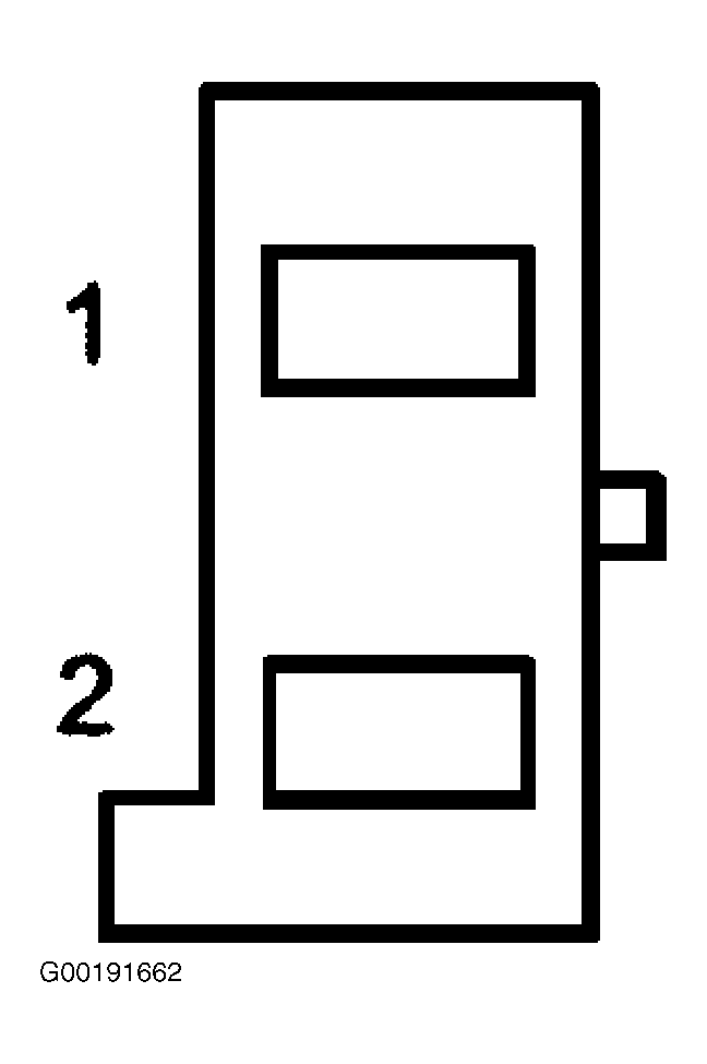
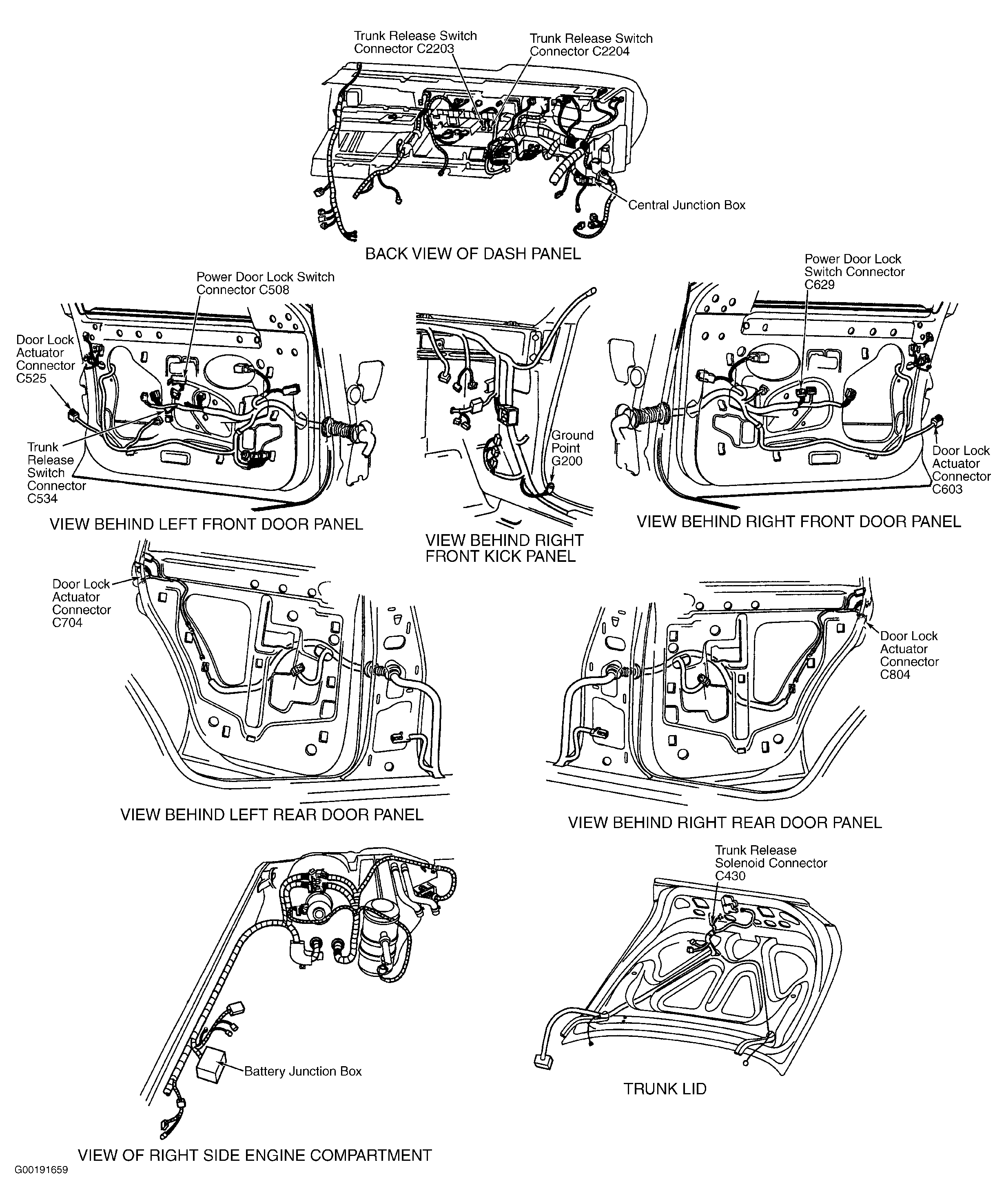
- Turn ignition switch to LOCK position. Disconnect trunk release switch 2-pin harness connectors C2203 and C2204, located at center of dash panel. See Figure. Turn ignition switch to RUN position. Measure voltage between ground and trunk release switch No. 1, harness connector C2203 terminal No. 1 (Black/White wire). Also measure voltage between ground and trunk release switch No. 2, harness connector C2204 terminals No. 1 (Yellow/Light Green wire). See Fig 1. See WIRING DIAGRAMS . If both voltage readings are greater than 10 volts, go to next step. If any voltage reading is 10 volts or less, repair open circuit in Black/White wire and/or Yellow/Light Green wire between trunk release switch and Battery Junction Box (BJB) and/or Central Junction Box (CJB). For Junction Box location, see Figure. After repair, test system for normal operation.
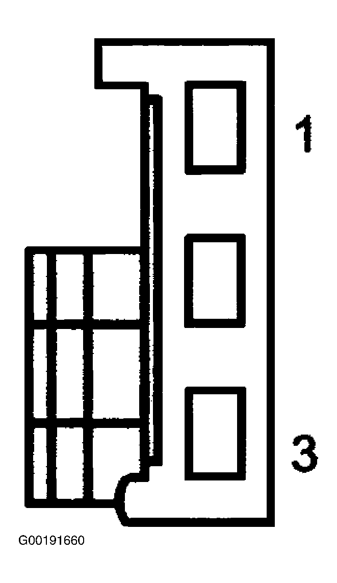
- Turn ignition switch to LOCK position. Reconnect trunk release switches. Disconnect trunk release solenoid 3-pin harness connector C430, located at center of trunk lid. See Figure. Turn ignition switch to RUN position. While pressing trunk release switches (one at the time), measure voltage between ground and trunk release solenoid harness connector C430 terminal No. 2 (Violet/Yellow wire). See Figure. See WIRING DIAGRAMS . If any voltage readings is 10 volts or less, go to next step. If both voltage readings are greater than 10 volts, go to step 4.
- Turn ignition switch to LOCK position. Disconnect trunk release switch harness connectors C2203 and C2204. Measure resistance between trunk release switch No. 1, harness connector C2203 terminal No. 2 and trunk release solenoid harness connector C430 terminal No. 2 (Violet/Yellow wire). See Figure and Fig 1 . See WIRING DIAGRAMS . Also measure resistance between trunk release switch No. 2, harness connector C2204 terminal No. 2 and trunk release solenoid harness connector C430 terminal No. 2 (Violet/Yellow wire). If any resistance is 5 ohms or less, replace appropriate trunk release switch. See TRUNK RELEASE SWITCH under REMOVAL & INSTALLATION. If any resistances is greater than 5 ohms, repair open circuit in Violet/Yellow wire between appropriate trunk release switch and trunk release solenoid. After repair, test system for normal operation.
- Measure resistance between ground and trunk release solenoid harness connector C430 terminal No. 3 (Black wire). See Figure. See WIRING DIAGRAMS . If resistance is 5 ohms or less, replace trunk release solenoid. If resistance is greater than 5 ohms, repair open circuit in Black wire between trunk release solenoid and ground point G200 located behind right kick panel. See Figure. After repair, test system for normal operation.