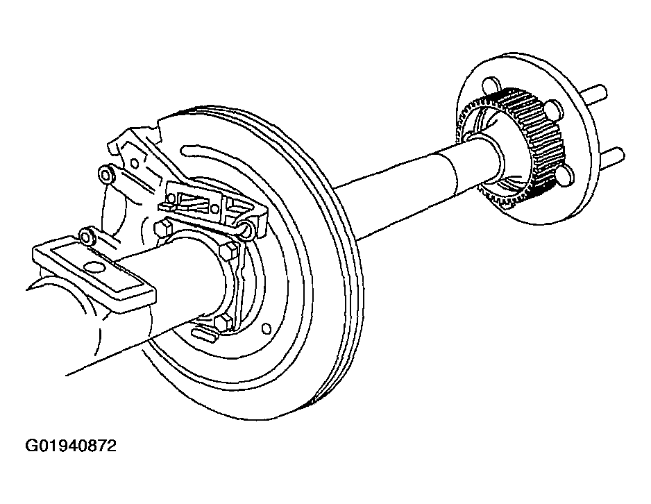
Axle Shaft: Removal
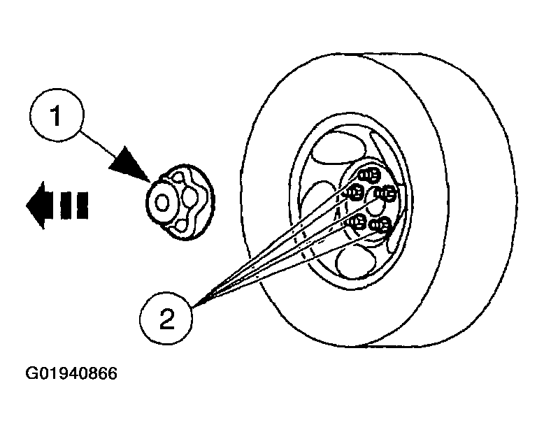
- Loosen the lug nuts.
- Remove the center cap.
- With the weight of the vehicle on the wheels, loosen the lug nuts.
- Raise and support the vehicle.
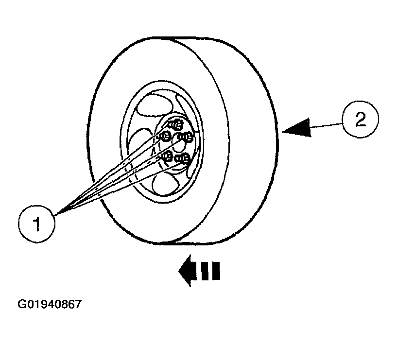
- Remove the rear wheel and tire assembly.
- Remove the lug nuts.
- Remove the wheel and tire assembly.
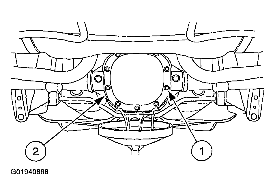
- Remove the differential housing cover.
- Remove the 10 differential housing cover bolts and drain the lubricant from the rear axle housing.
- Remove the differential housing cover.
- Remove the rear brake anti-lock sensor. For additional information, refer to SENSOR -- ANTI-LOCK BRAKE, REAR .
- Remove the rear brake caliper and the brake disc. For additional information, refer to REAR BRAKE ROTOR .
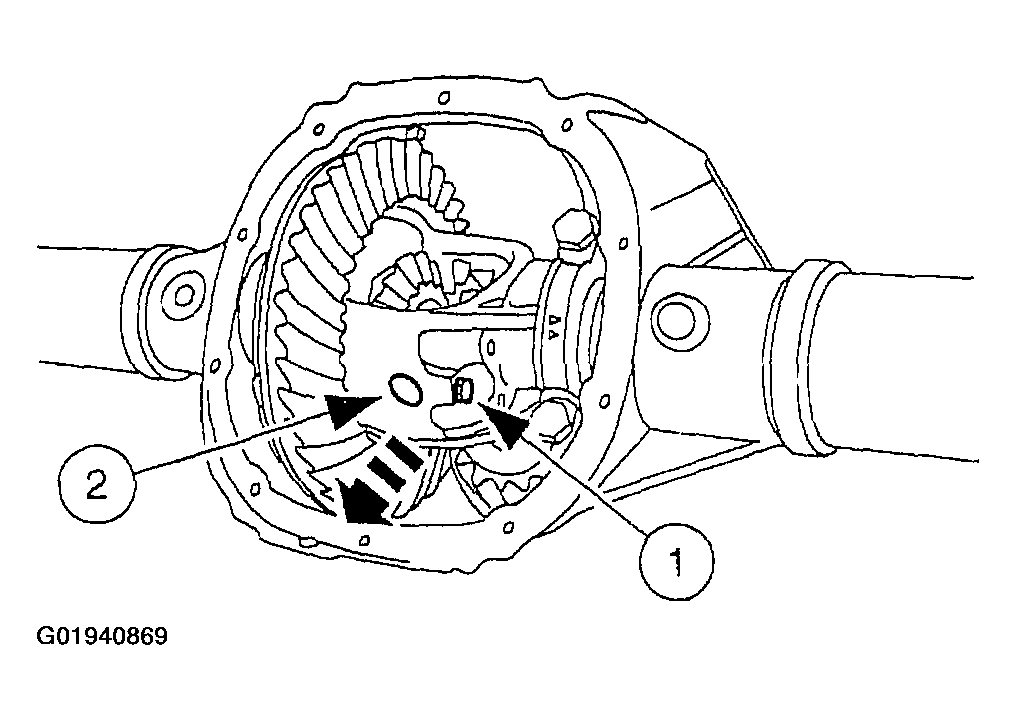
- Remove the differential pinion shaft.
- Remove the differential pinion shaft lock bolt.
- Remove the differential pinion shaft.
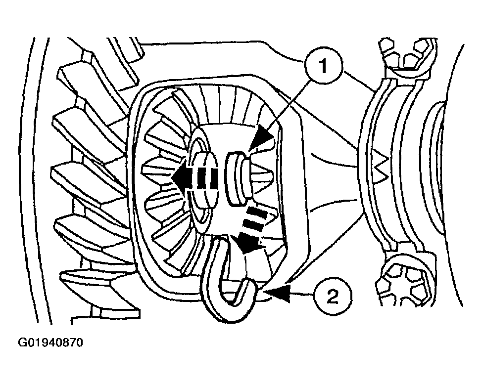
- Remove the U-washer.
- Push the axle shaft inboard.
- Remove the U-washer.
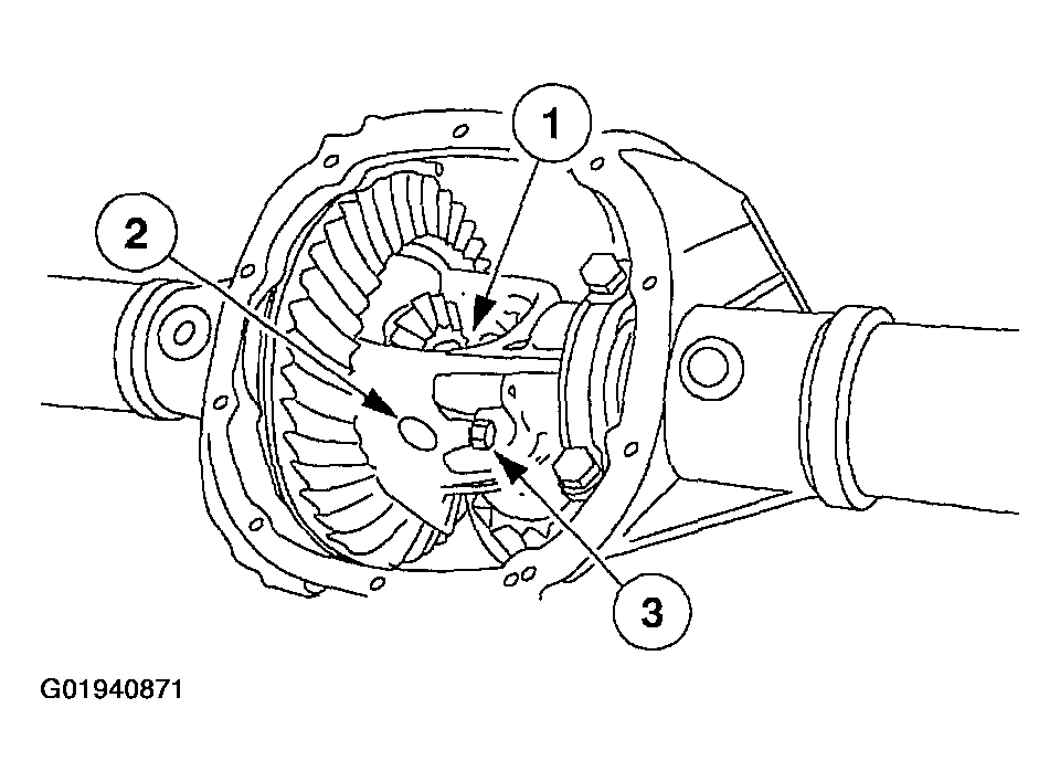
- Reinstall the differential pinion shaft.
- Push the axle shaft outboard.
- Install the differential pinion shaft.
- Install the differential pinion shaft lock bolt finger-tight.
- Remove the axle shaft.
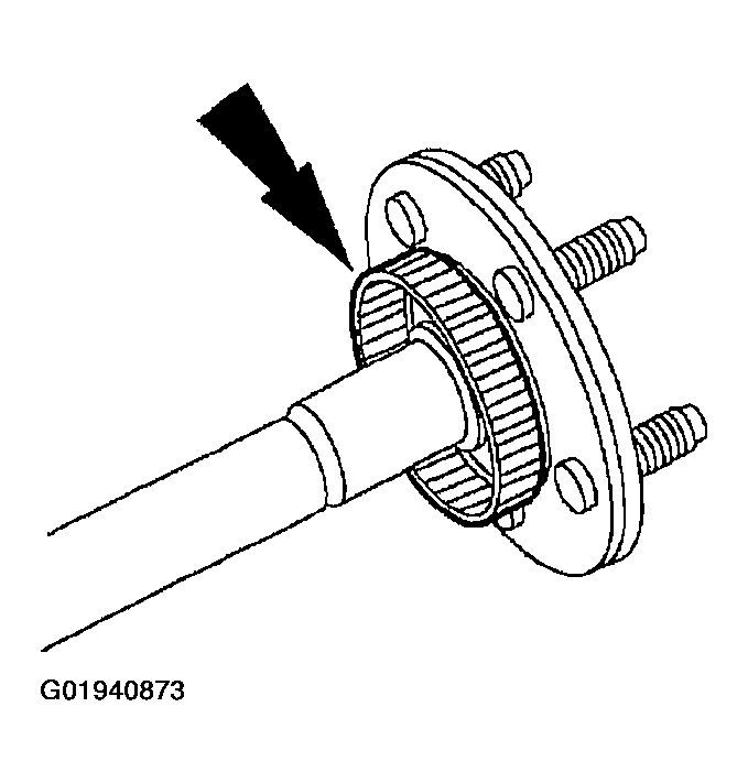
- Using a thin-blade cold chisel between the rear brake anti-lock sensor indicator and the axle shaft, strike the chisel evenly around the flange. Force the rear anti-lock sensor indicator off the rear brake anti-lock sensor indicator journal. Discard the rear brake anti-lock sensor indicator.
CAUTION:
Do not use heat to loosen a seized lug nut. Heat can damage the wheel and the rear wheel bearings.
WARNING:
When equipped with rear air springs, the electrical power to the air suspension system must be shut off prior to hoisting, jacking or towing an air suspension vehicle. This can be accomplished by turning off the air suspension switch located in the RH kick panel area. Failure to do so can result in unexpected inflation or deflation of the air springs, which can result in shifting of the vehicle during these operations.
CAUTION:
Once the differential pinion shaft has been removed, turning the differential case or an axle shaft can cause the differential pinion gears to fall out of the assembly. This can result in chipped or damaged components.
 Courtesy of FORD MOTOR CO.
CAUTION:
Do not damage the rubber O-ring in the U-washer groove.
CAUTION:
Do not damage the wheel bearing oil seal.