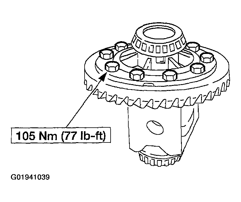
Differential Case & Ring Gear - Traction-LOK®: Assembly
- Lubricate each steel clutch plate and soak all the friction plates for no less than 15 minutes.
- Use Additive Friction Modifier C8AZ-19B546-A or equivalent meeting Ford specification EST-M2C118-A
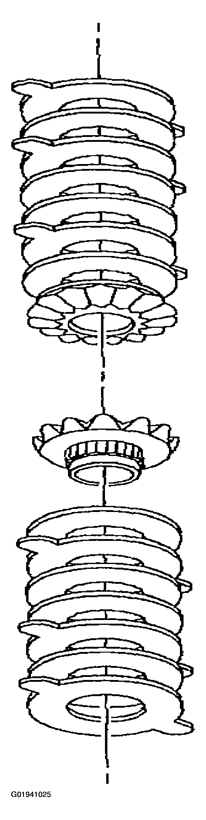
- Assemble the differential clutch packs (without the shims) on their respective differential side gear.
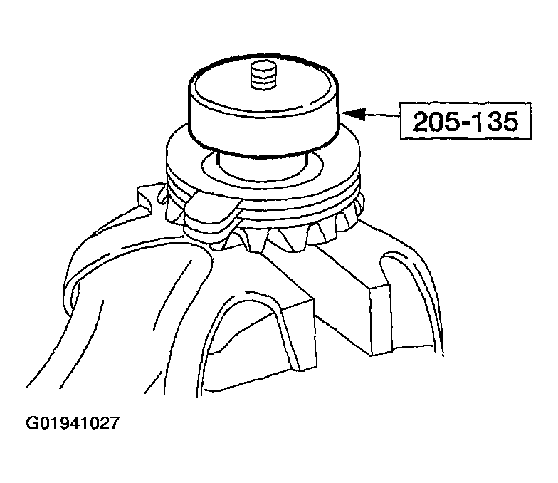
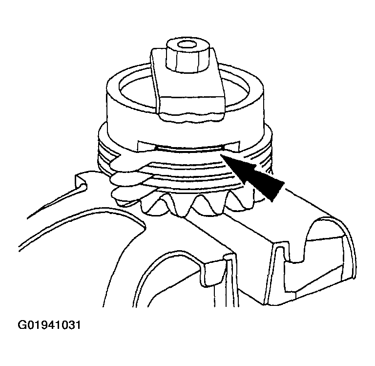
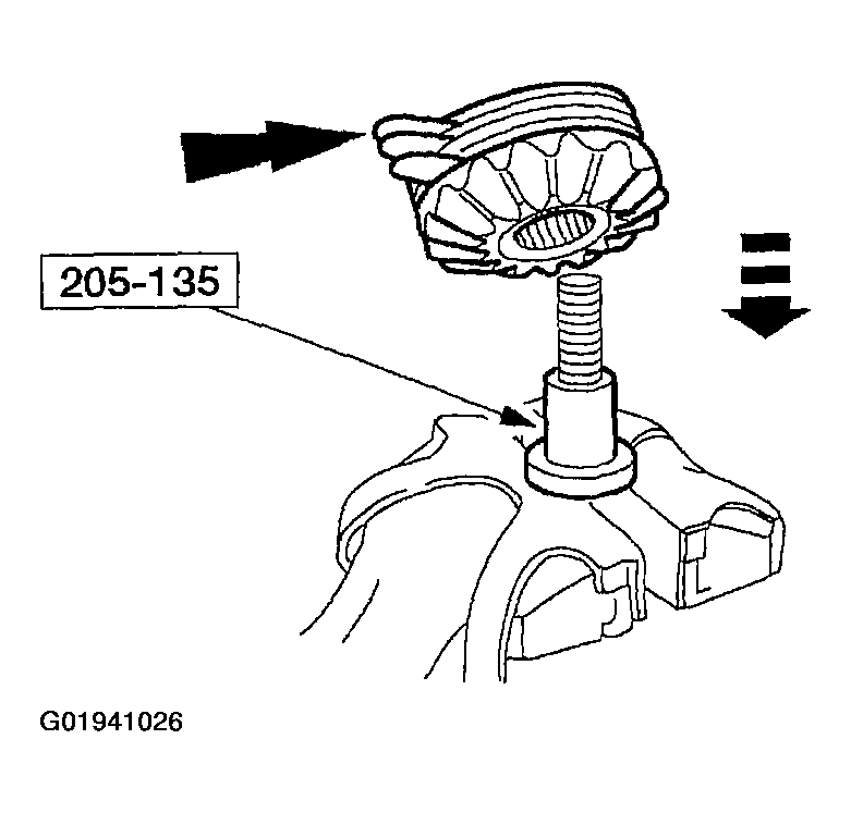
- Place the base portion of the special tool in a vise. Install the differential side gear and differential clutch pack (without the shim) on the tool.
- Position the special tool hand-tight on top of the differential clutch pack.
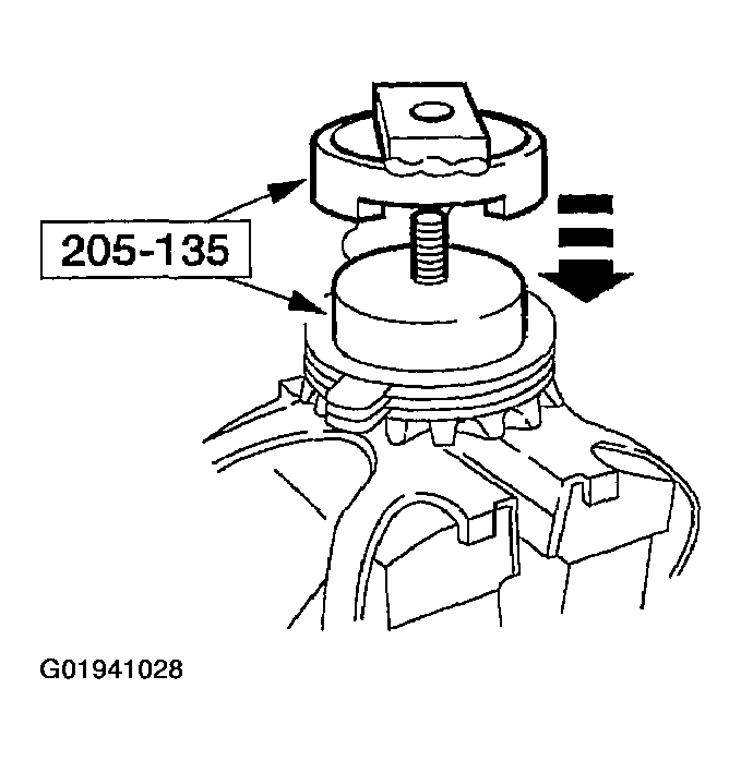
- Install the special tool over the disc and differential clutch pack.
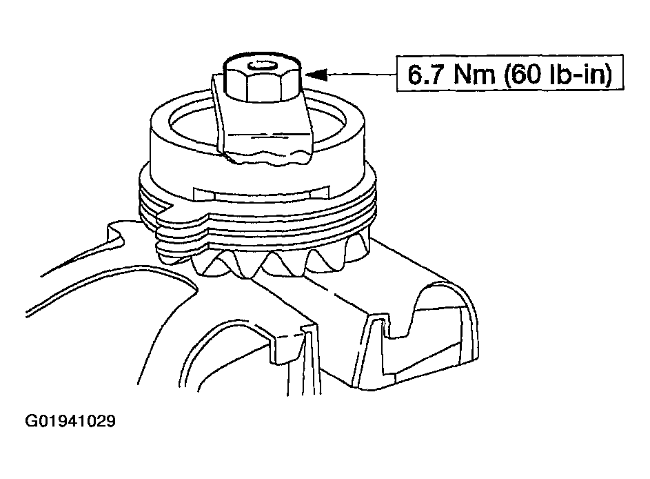
- Install the nut.
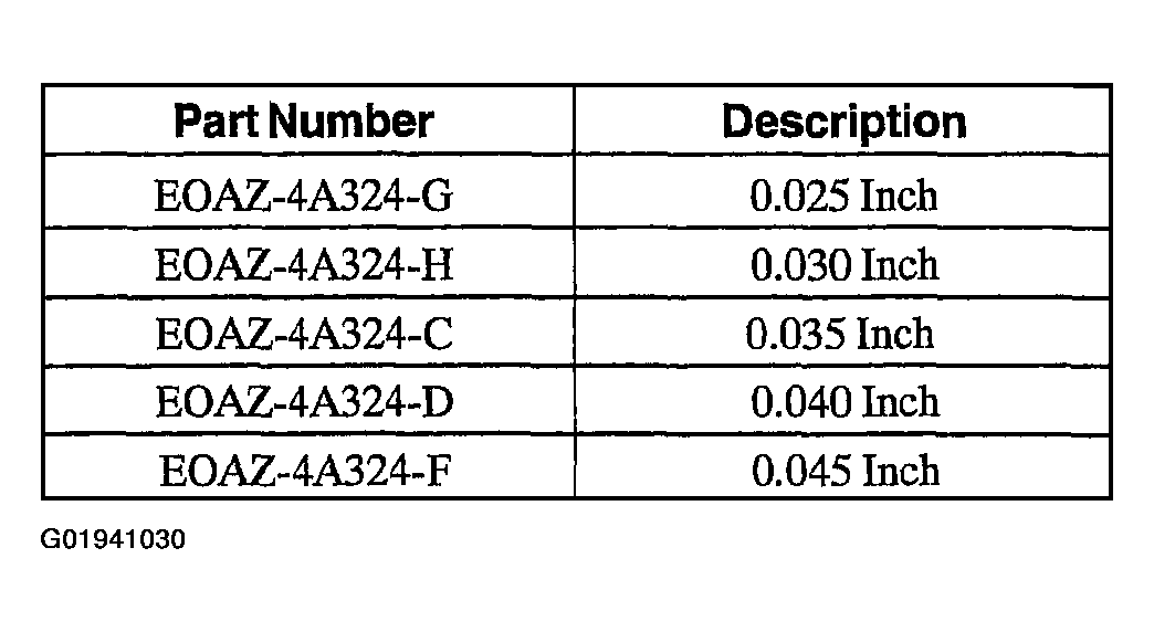
- Select and insert the thickest feeler gauge blade that will enter between the tool and the differential clutch pack. The reading will be the thickness of the new clutch shim.
- Remove the special tool from the differential clutch pack and differential side gear assembly.
- Install the shim(s) on the differential clutch pack and differential side gear assembly.
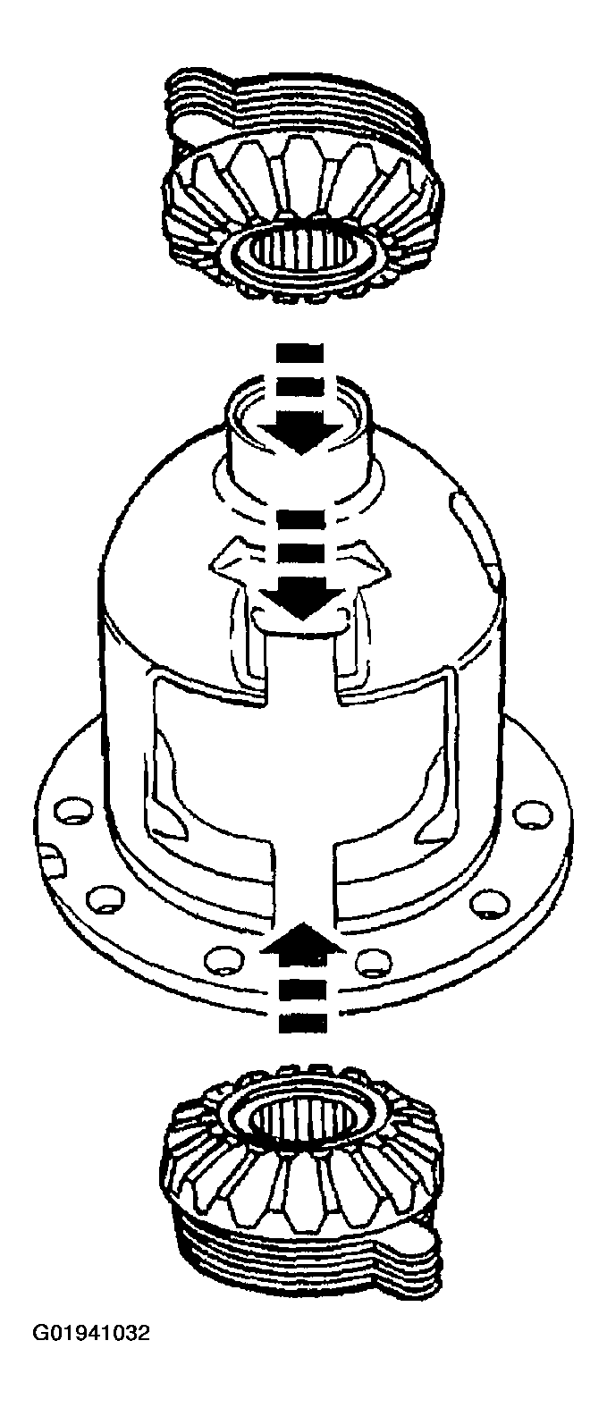
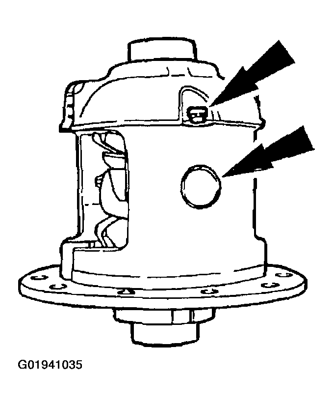
- Install the differential side gear assemblies in the differential case.
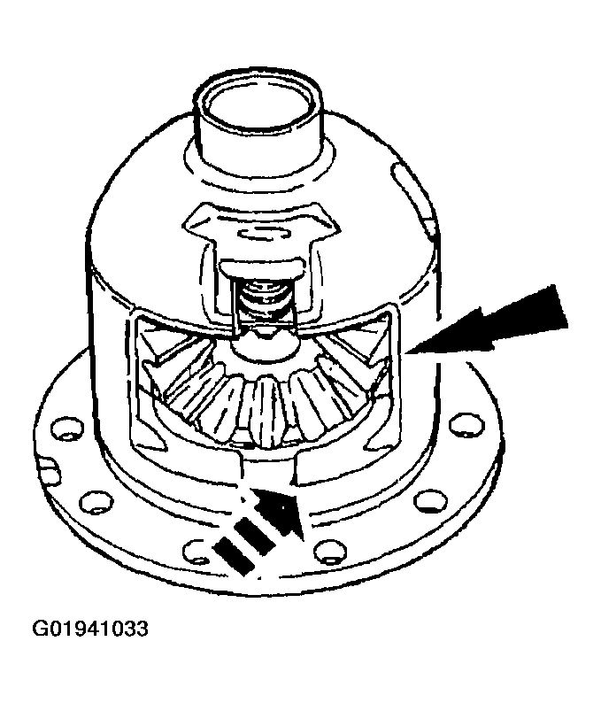
- Install the differential pinion gear and differential pinion thrust washer assemblies in the differential case.
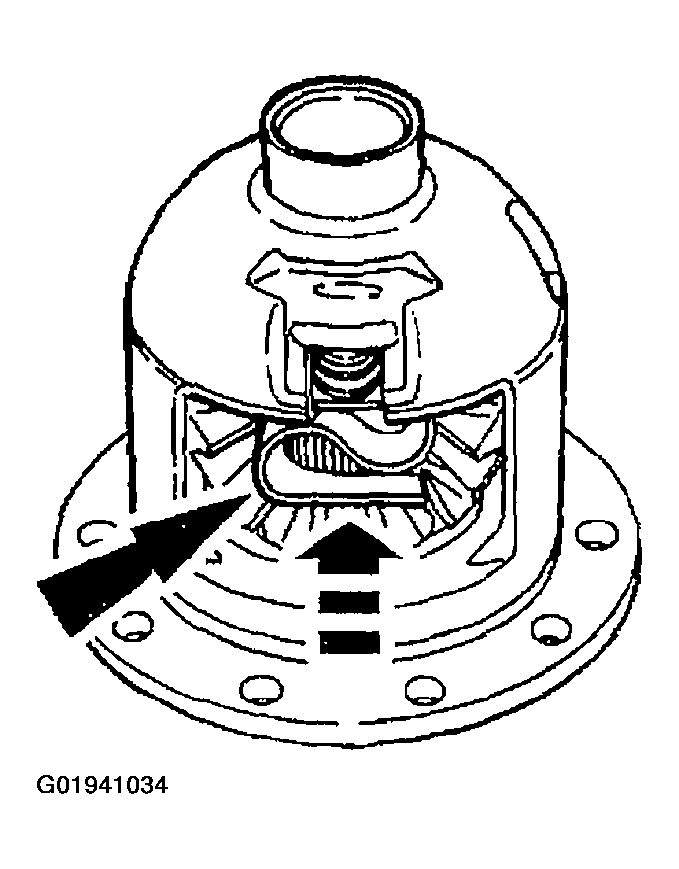
- Using a soft-faced hammer, install the differential clutch spring.
- Install the differential pinion shaft and install a new bolt finger-tight.
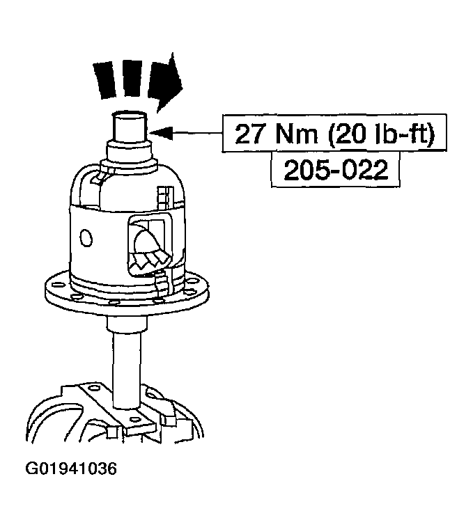
- Mount the differential case and the special tool in a vise. Using the special tool, check the torque necessary to rotate one differential side gear.
- If reusing the original clutch plates, the initial minimum break-away torque must be no less than the specification. The minimum rotating torque necessary to keep the differential side gear turning with new clutch plates may vary.
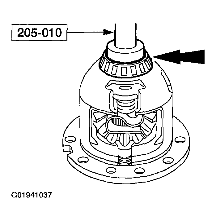
- Using the special tool, install the differential bearings.
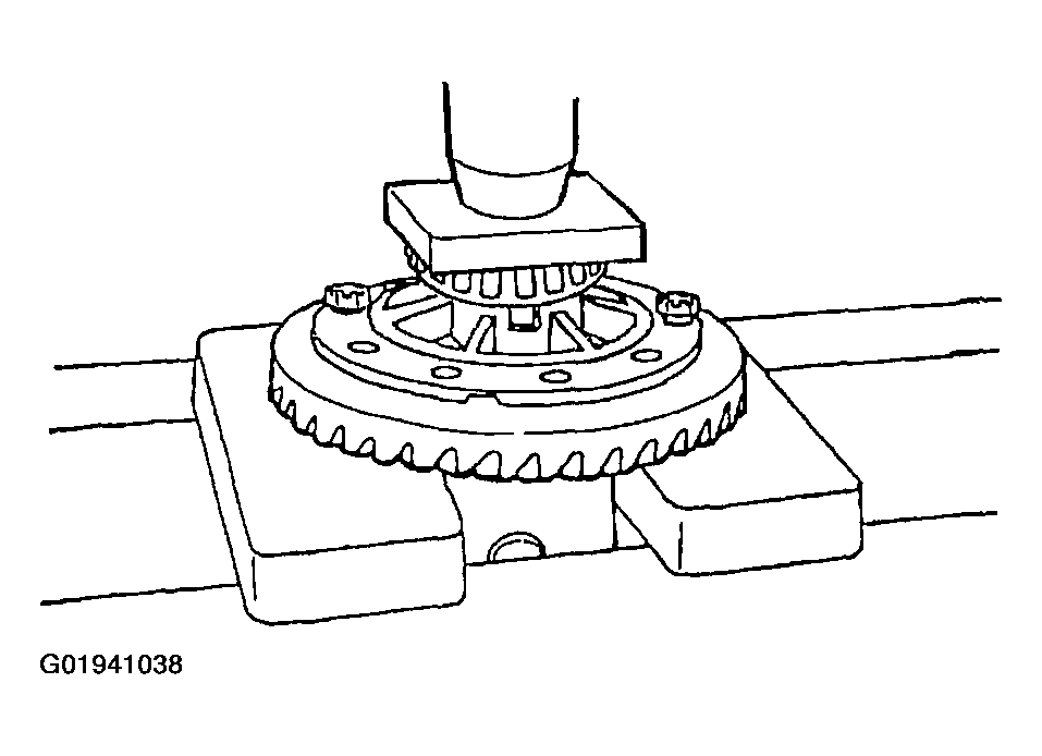
- Position the differential ring gear and the differential case. Align the bolt holes by starting two bolts through the holes in the differential case and the differential ring gear. Press the differential ring gear on the differential case.
- Install the bolts.
- Apply Stud and Bearing Mount E0AZ-19554-BA or equivalent meeting Ford specification WSK-M2G349-A1 to bolt threads.
- Install the differential assembly. For additional information, refer to DIFFERENTIAL CASE .
CAUTION:
118 ml (4 oz) of the Additive Friction Modifier must be used in the axle.
CAUTION:
Do not mix the clutch plates, clutch discs or shim from one side with the other.
CAUTION:
Use the correct mandrel with the special tool.
 Courtesy of FORD MOTOR CO.