Supplemental Restraint System (SRS) Deactivation and Reactivation: Reactivation
WARNING:
To reduce the risk of serious personal injury, read and follow all warnings, cautions, and notes at the beginning of the deactivation procedure.
- Disconnect the battery ground cable and wait at least one minute.
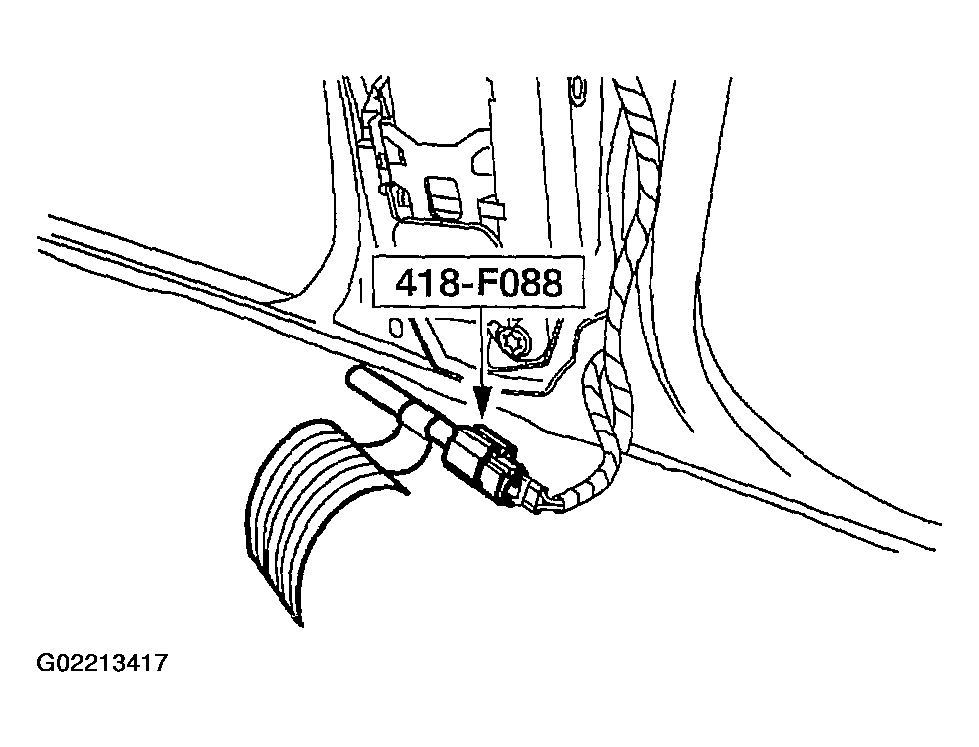
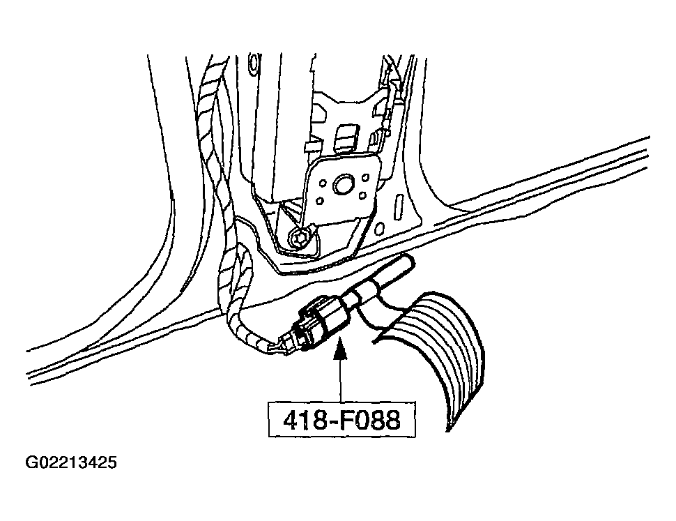
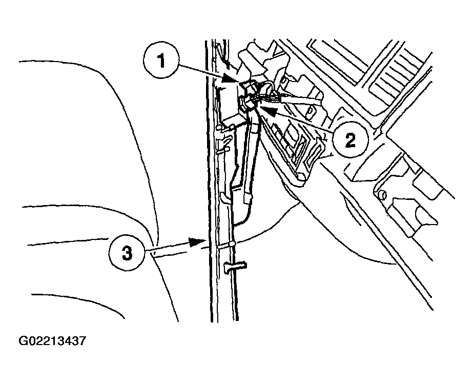
- Remove the restraint system diagnostic tool from the driver safety belt retractor pretensioner electrical connector.
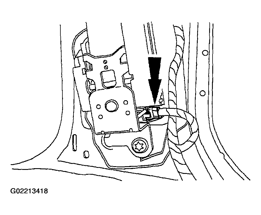
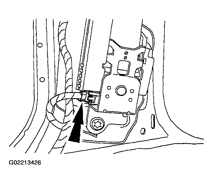
- Connect the driver safety belt retractor pretensioner electrical connector.
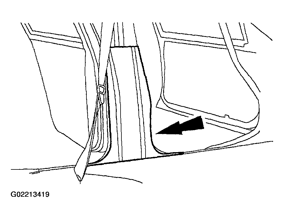
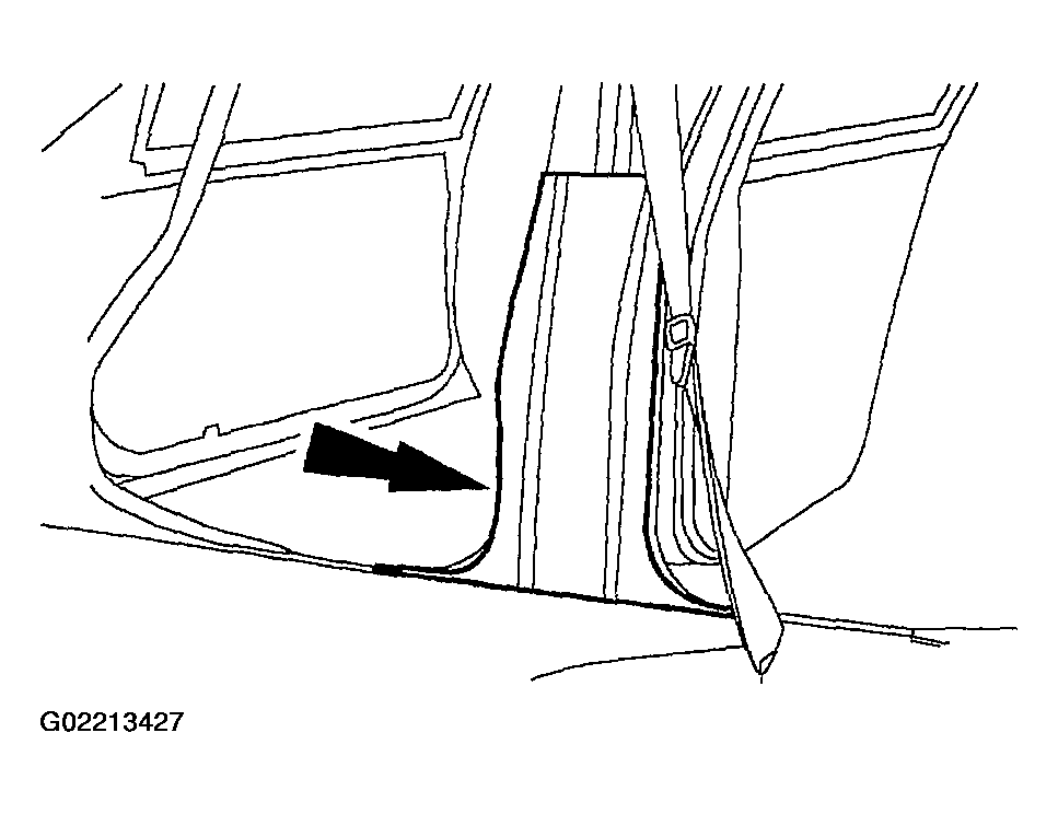
- Align the driver side B-pillar lower trim panel and push in, seating the retaining clips.
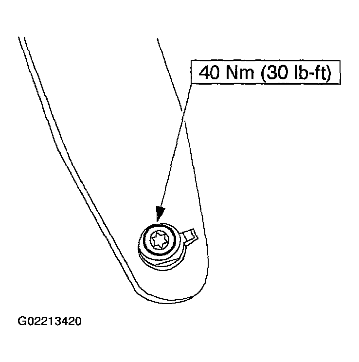
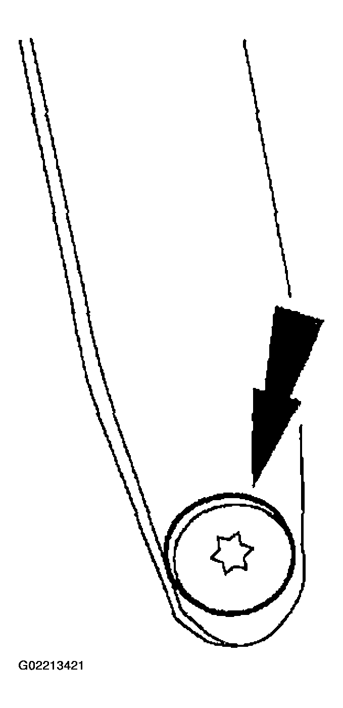
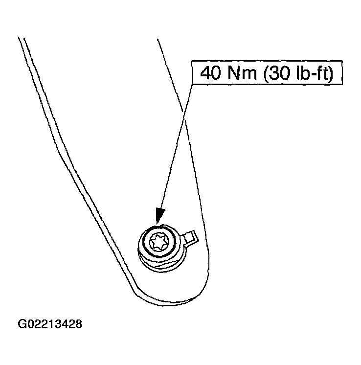
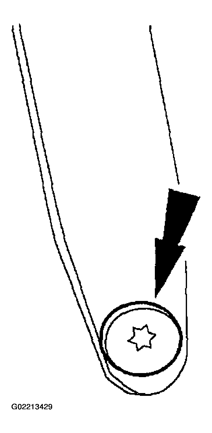
- Position the driver side safety belt anchor. Install the bolt.
- Install the driver side safety belt anchor bolt cover.
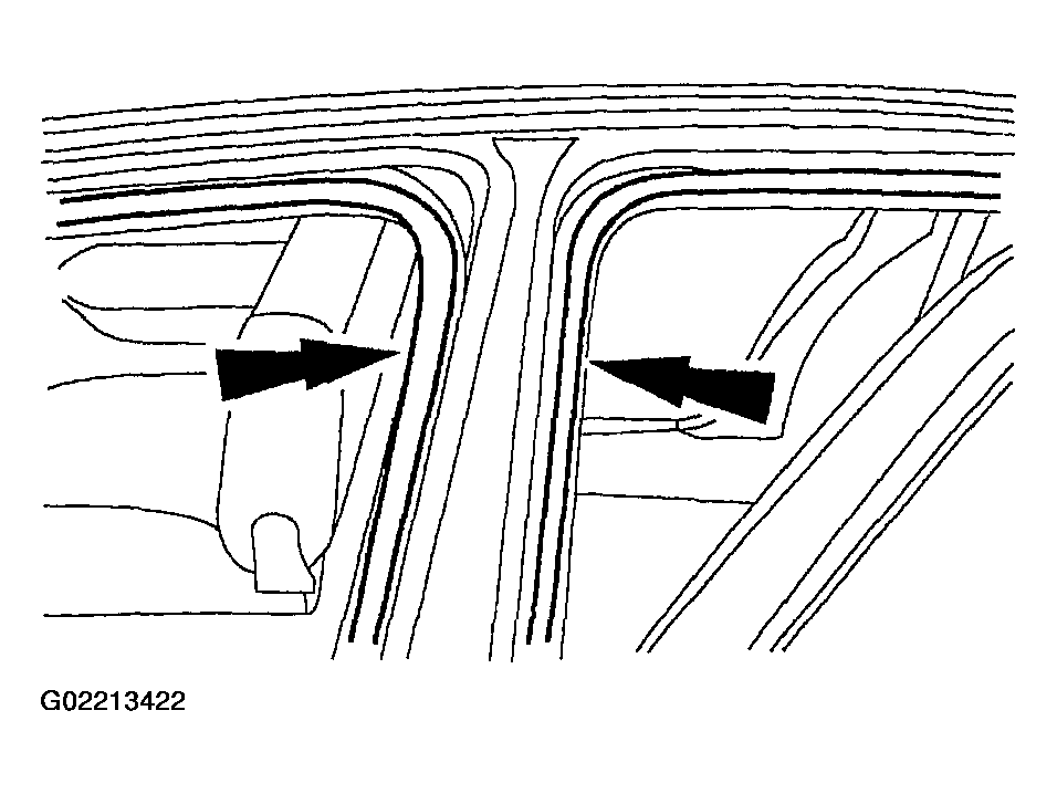
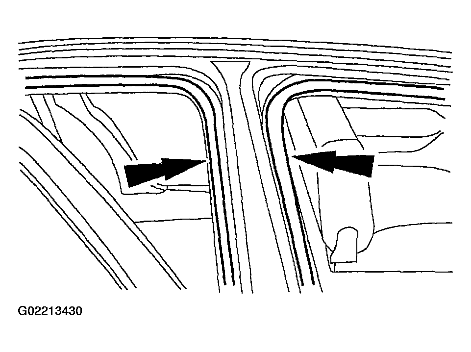
- Install the driver side B-pillar weather-stripping.
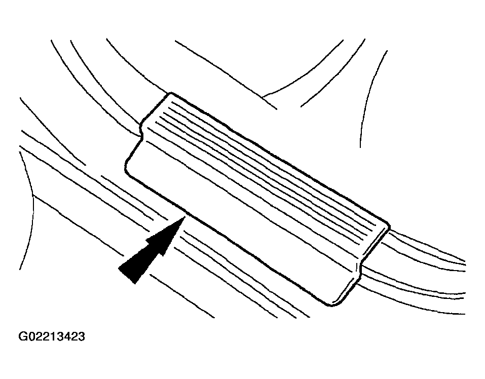
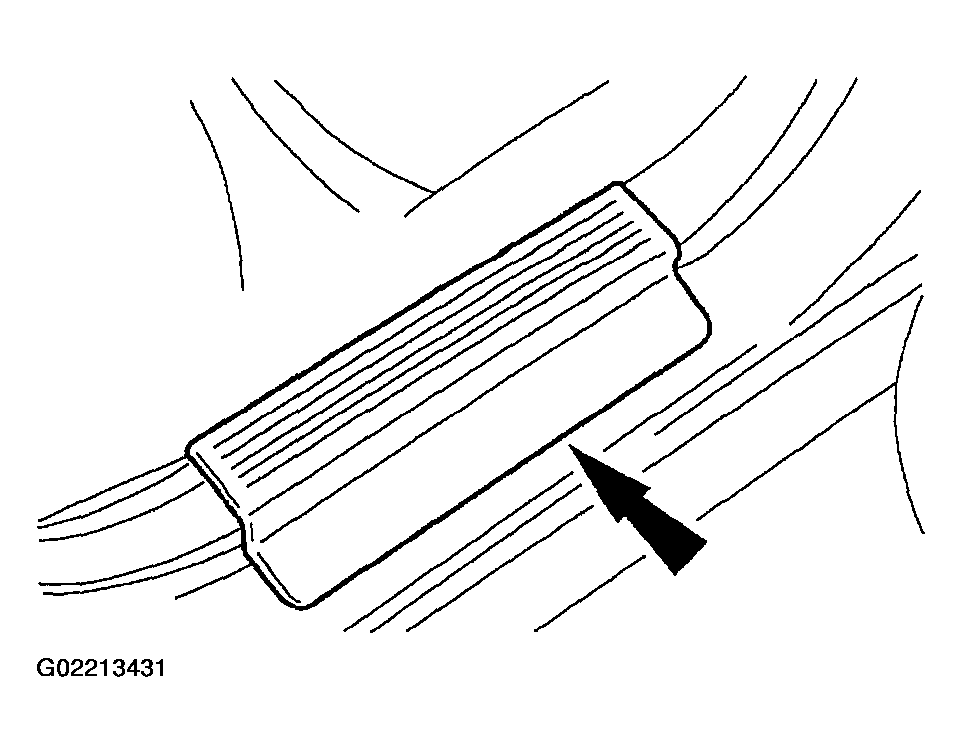
- Install the driver side rear door scuff plate.
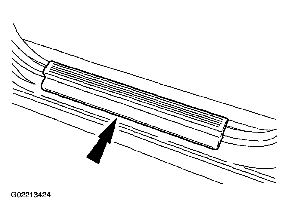
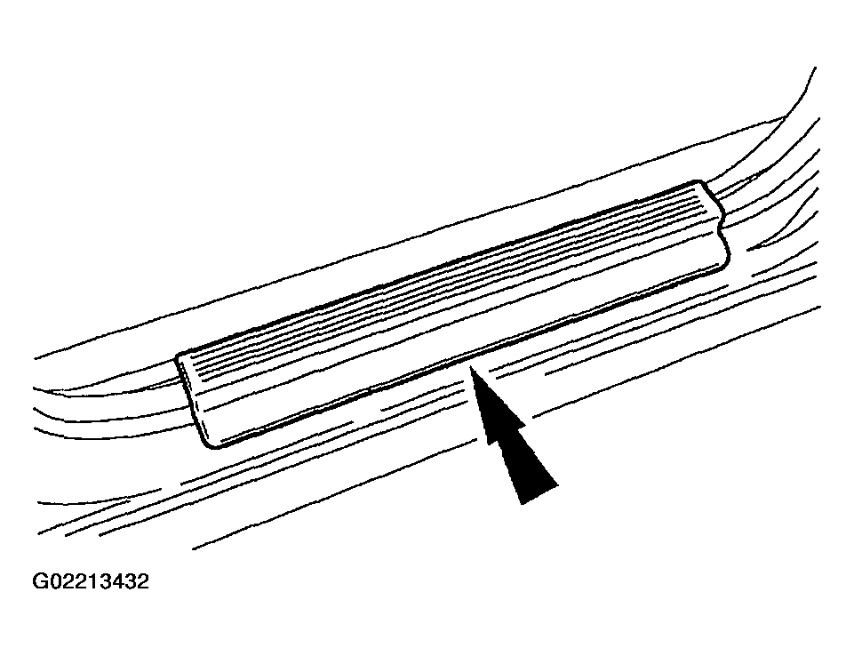
- Install the driver side front door scuff plate.
- Remove the restraint system diagnostic tool from the passenger safety belt retractor pretensioner electrical connector.
- Connect the passenger safety belt retractor pretensioner electrical connector.
- Align the passenger side B-pillar lower trim panel and push in, seating the retaining clips.
- Position the passenger safety belt anchor. Install the bolt.
- Install the passenger side safety belt anchor bolt cover.
- Install the passenger side B-pillar weather-stripping.
- Install the passenger side rear door scuff plates.
- Install the passenger side front door scuff plate.
- Connect the battery ground cable.
- Position the front seats rearward.
- Disconnect the battery ground cable and wait at least one minute.
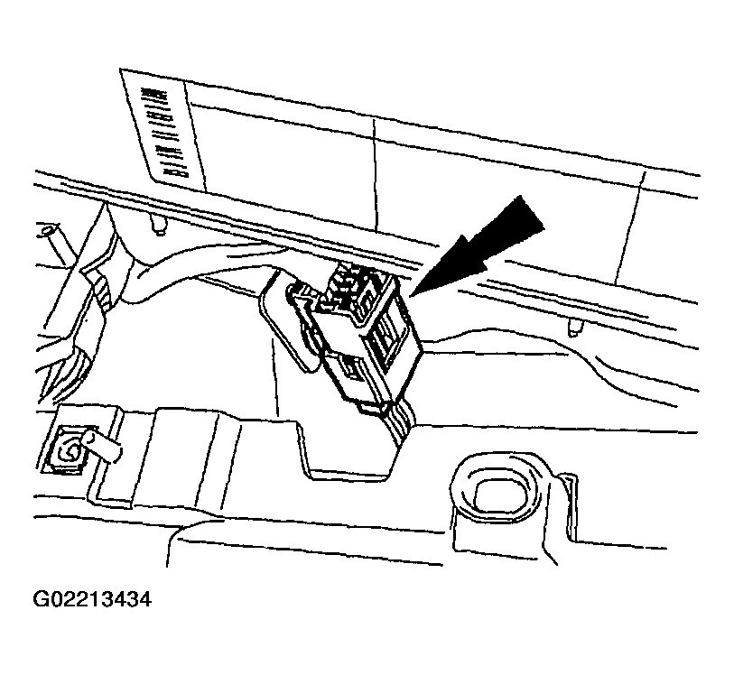
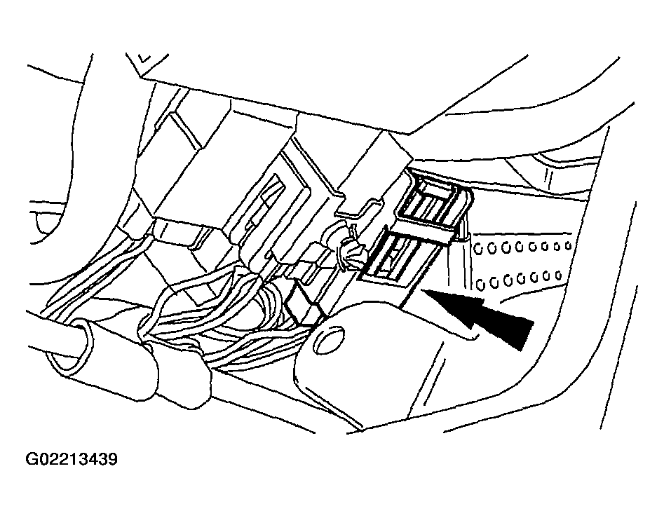
- Remove the restraint system diagnostic tool from the passenger air bag module electrical connector.
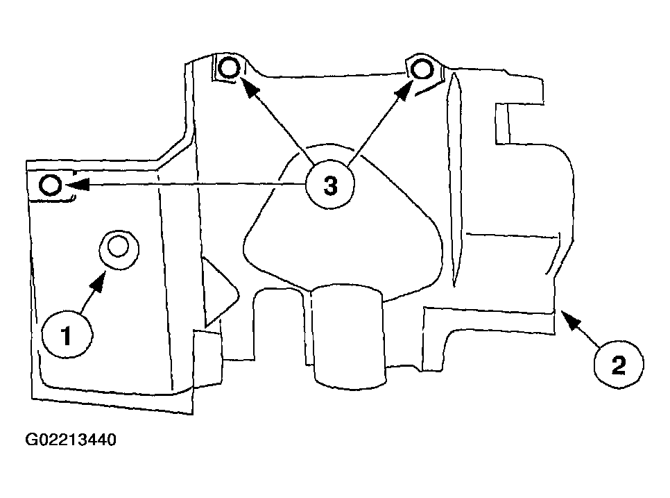
- Make sure the J-clips on the back of the passenger air bag module are fully seated into the slots.
- Position the passenger air bag module to the instrument panel. Connect the passenger air bag module electrical connector.
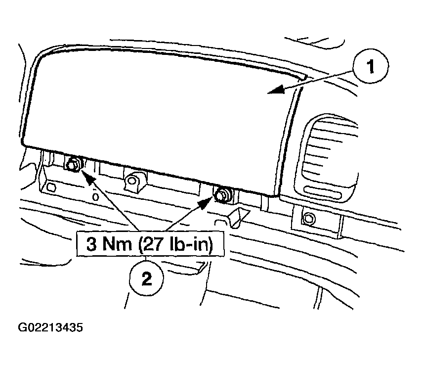
- Install the passenger air bag module into the instrument panel.
- Install the passenger air bag module into the instrument panel.
- Install the bolts.
- Through the glove compartment opening, install the passenger air bag module bolts.
- Install the trim panel.
- Connect the rear window defrost switch electrical connector.
- Connect the clock electrical connector.
- Align the retaining clips, slide the trim panel to the left and push in, seating the retaining clips.
- Connect the glove compartment isolator. Close the glove compartment.
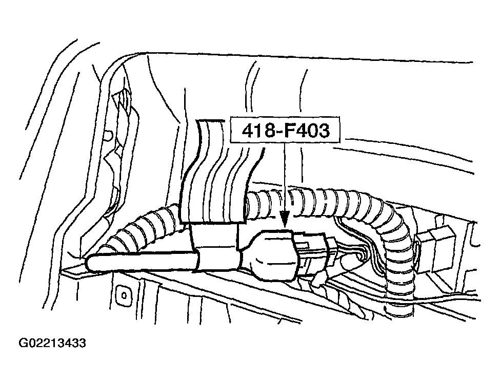
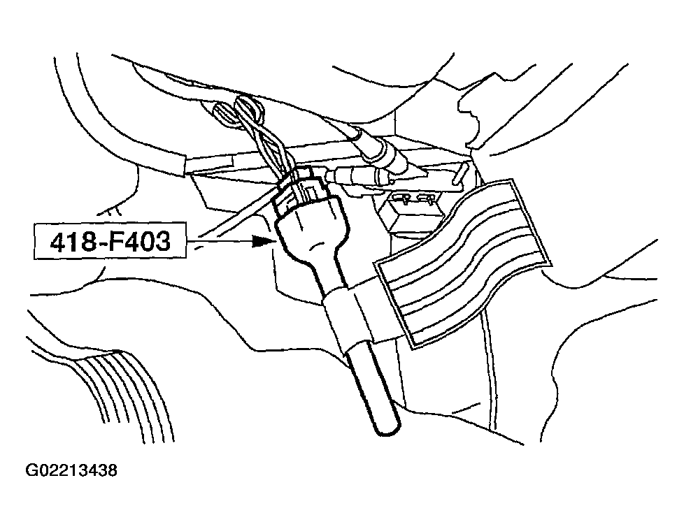
- Remove the restraint system diagnostic tool from the clockspring electrical connector.
- Connect the clockspring electrical connector at the base of the steering column.
- Install the LH lower instrument panel insulator.
- Install the courtesy lamp.
- Slide the LH lower instrument panel insulator into the front retaining bracket (not shown).
- Install the pin-type retainers.
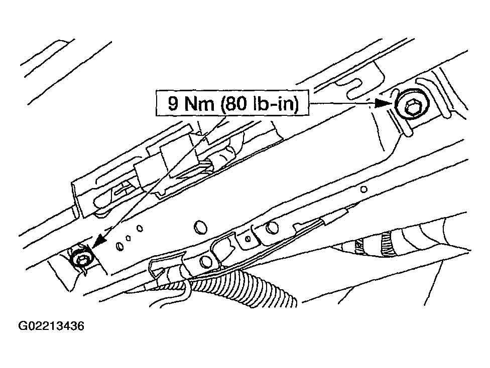
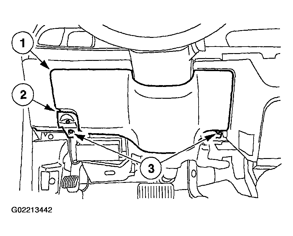
- Position the steering column opening lower reinforcement. Install the bolts.
- Install the steering column opening lower finish panel.
- Align the steering column opening lower finish panel and push in, seating the retaining clips.
- Position the parking brake release assembly.
- Install the screws.
- Connect the battery ground cable.
- With all the restraint system diagnostic tools removed, prove out the supplemental restraint system (SRS). For additional information, refer to AIR BAG RESTRAINT SYSTEMS .
- Check the active restraint system for correct operation.
WARNING:
To avoid accidental deployment and possible personal injury, the backup power supply must be depleted before repairing or replacing any front or side air bag supplemental restraint system (SRS) components and before servicing, replacing, adjusting or striking components near the front or side air bag sensors, such as doors, instrument panel, console, door latches, strikers, seats and hood latches.
Please refer to AIR BAG RESTRAINT SYSTEMS to determine location of the front air bag sensors.
The side air bag sensors are located at or near the base of the B-pillar.
To deplete the backup power supply energy, disconnect the battery ground cable and wait at least one minute. Be sure to disconnect auxiliary batteries and power supplies (if equipped).
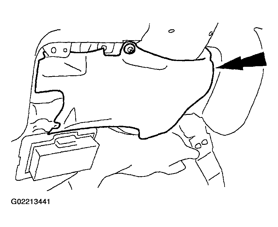
WARNING:
The restraint system diagnostic tool is for restraint system service only. Remove from vehicle prior to road use. Failure to remove could result in injury and possible violation of vehicle safety standards.