Test A: Cruise Control Is Inoperative
NOTE:
Ensure brakelights are operating properly before beginning this procedure.
NOTE:
Perform all voltage and resistance tests using a Digital Volt-Ohm Meter (DVOM) with a minimum 10-megohm input impedance, unless stated otherwise in test procedure. Use ohmmeter to isolate wiring harness shorts or opens.
- Turn ignition switch to LOCK position. Remove accelerator control splash shield. Inspect cruise control cable attachment at throttle body. If cruise control cable is attached, go to next step. If cruise control cable is not attached, repair as necessary. After repair, test system for normal operation.
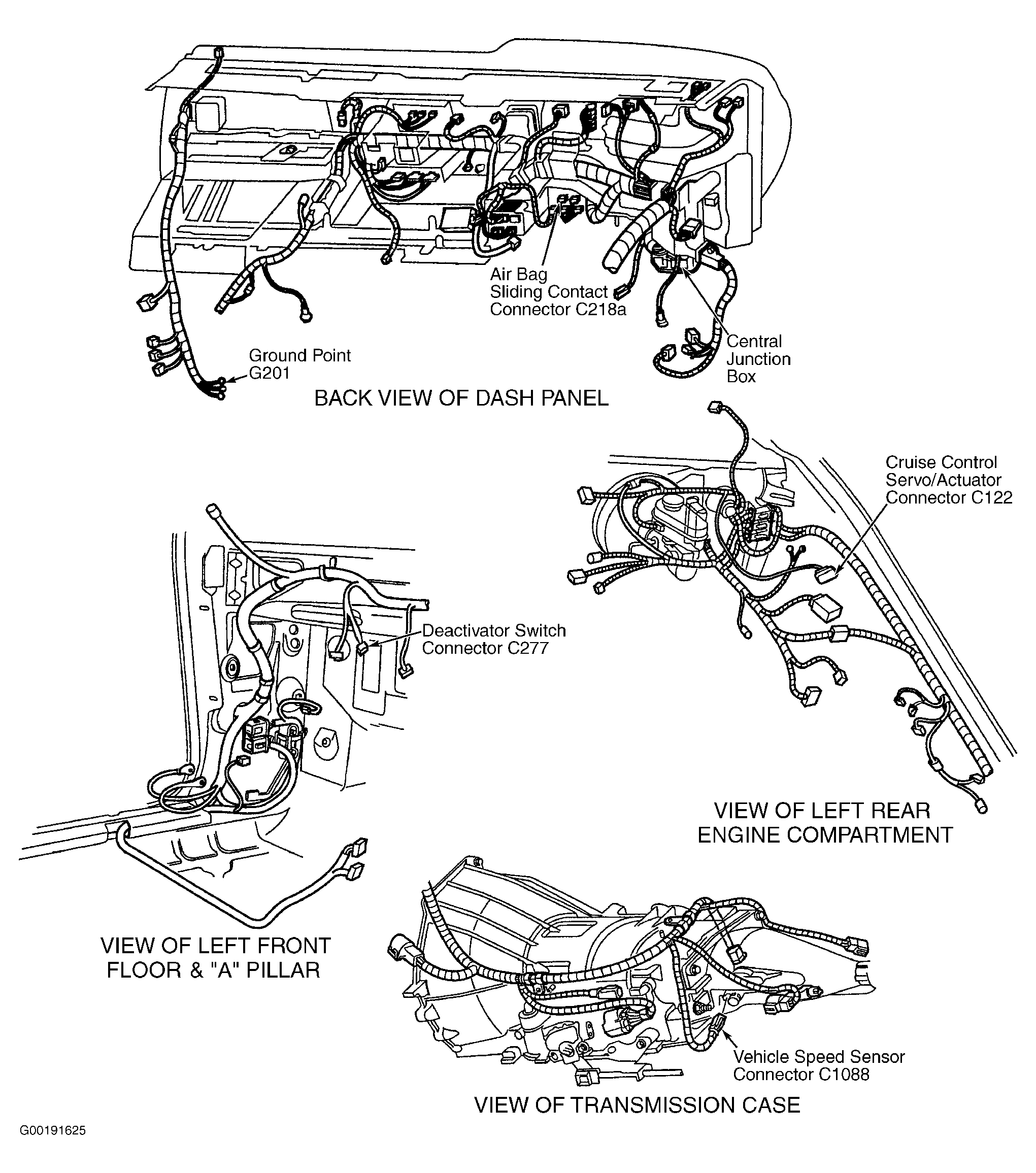
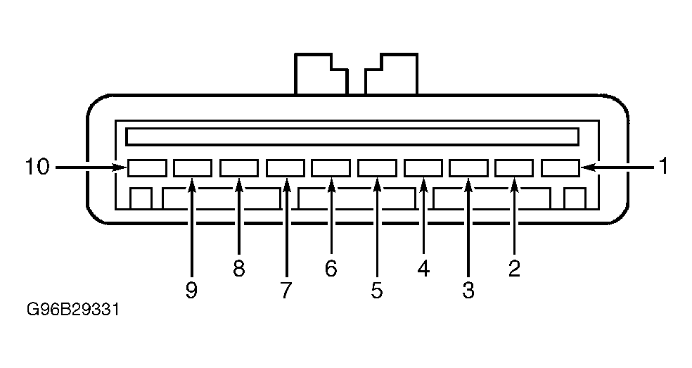
- Disconnect cruise control servo/actuator 10-pin harness connector C122. Cruise control servo/actuator harness connector C122 is located at left rear engine compartment. See Figure. Turn ignition switch to RUN position. Measure voltage between cruise control servo/actuator harness connector C122 terminals No. 7 (White/Violet wire) and No. 10 (Pink/Orange wire). See Fig 1. See WIRING DIAGRAMS . If voltage is greater than 10 volts, go to next step. If voltage is 10 volts or less, go to step 4.
- Turn ignition switch to LOCK position. Measure resistance between ground and cruise control servo/actuator harness connector C122 terminal No. 10 (Pink/Orange wire). See Fig 1. See WIRING DIAGRAMS . If resistance is 5 ohms or less, repair open or short circuit to ground in White/Violet wire between cruise control servo/actuator and Central Junction Box (CJB). CJB is located under left side of dash panel. See Figure. If resistance is greater than 5 ohms, repair open circuit in Pink/Orange wire between cruise control servo/actuator and ground point G201. Ground point G201 is located under right rocker panel. See Figure. After repair, clear DTC and test system for normal operation.
- Ensure brake pedal is not depressed, and ignition switch is on LOCK position. Measure voltage between cruise control servo/actuator harness connector C122 terminals No. 4 (Light Green wire) and No. 10 (Pink/Orange wire). See Fig 1. See WIRING DIAGRAMS . If voltage does not exist, go to next step. If voltage exists, replace brake pedal position switch. See BRAKE PEDAL POSITION SWITCH under REMOVAL & INSTALLATION. After repair, test system for normal operation.
- Measure resistance between cruise control servo/actuator harness connector C122 terminals No. 4 (Light Green wire) and No. 10 (Pink/Orange wire). See Fig 1. See WIRING DIAGRAMS . If resistance is 20 ohms or less, go to next step. If resistance is greater than 20 ohms, repair open circuit in Light Green wire between cruise control servo/actuator and brake pedal position switch. After repair, test system for normal operation.
- Measure voltage between cruise control servo/actuator harness connector C122 terminals No. 9 (Orange wire) and No. 10 (Pink/Orange wire). See Fig 1. If voltage is 10 volts or less, go to next step. If voltage is greater than 10 volts, go to step 9.
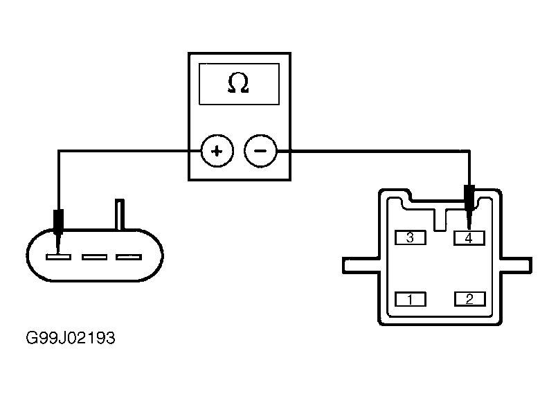
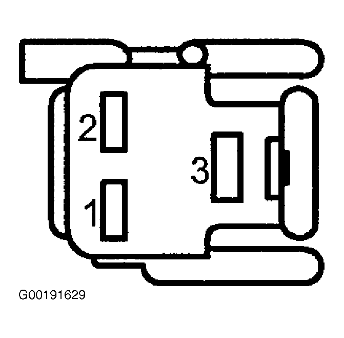
- Disconnect cruise control deactivator switch 3-pin harness connector C277. See Fig 2. Cruise control deactivator switch harness connector C277 is located on brake pedal support. See Figure. Measure resistance between cruise control deactivator switch terminals No. 1 and 2 (component side). If resistance is less than 5 ohms, go to next step. If resistance is 5 ohms or greater, replace cruise control deactivator switch. See DEACTIVATOR SWITCH under REMOVAL & INSTALLATION. After repair, test system for normal operation.
- Measure voltage between ground and cruise control deactivator switch harness connector C277 terminal No. 1 (Light Green/Red wire). See Fig 2. See WIRING DIAGRAMS . If voltage is greater than 10 volts, repair open circuit in Orange wire between cruise control deactivator switch and cruise control servo/actuator. If voltage is 10 volts or less, repair open circuit in Light Green/Red wire between cruise control deactivator switch and Central Junction Box (CJB). CJB is located under left side of dash panel. See Figure. After repair, clear DTC and test system for normal operation.
- Ensure cruise control switch is off. Measure voltage between cruise control servo/actuator harness connector C122 terminals No. 5 (Light Blue/Black wire) and No. 10 (Pink/Orange wire). See Fig 1. See WIRING DIAGRAMS . If voltage is 10 volts or less, go to next step. If voltage is greater than 10 volts, replace cruise control switch. See CRUISE CONTROL SWITCHES under REMOVAL & INSTALLATION. After repair, test system for normal operation.
- While depressing cruise control switch to ON position, measure voltage between cruise control servo/actuator harness connector C122 terminals No. 5 (Light Blue/Black wire) and No. 10 (Pink/Orange wire). See Fig 1. See WIRING DIAGRAMS . If voltage is 10 volts or less, go to next step. If voltage is greater than 10 volts, go to step 13. After repair, test system for normal operation.
- Turn ignition switch to LOCK position. Deactivate air bag system. See DISABLING & ACTIVATING AIR BAG SYSTEM in AIR BAG RESTRAINT SYSTEMS article in RESTRAINTS. Disconnect lower air bag sliding contact 4-pin harness connector C218c. Lower air bag sliding contact harness connector C218c is located under dash panel, on steering column. See Figure. Measure resistance between air bag sliding contact harness connector C218c terminal No. 4 and cruise control servo/actuator harness connector C122 terminal No. 6 (Dark Green/Orange wire). See Fig 1 and Fig 3 . See WIRING DIAGRAMS . If resistance is 5 ohms or less, go to next step. If resistance is greater than 5 ohms, repair open circuit in Dark Green/Orange wire between air bag sliding contact and cruise control servo/actuator. After repair, test system for normal operation.
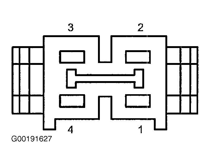
- Remove driver's air bag module. See DUAL-STAGE DRIVER-SIDE AIR BAG MODULE under REMOVAL & INSTALLATION in AIR BAG RESTRAINT SYSTEMS article in RESTRAINTS. Disconnect top air bag sliding contact 3-pin harness connector. Measure resistance between lower air bag sliding contact connector C218c terminal No. 4 and top air bag sliding contact connector terminals No. 3 (air bag sliding contact harness connectors side). See Fig 4. See WIRING DIAGRAMS . If resistance is less than one ohm, replace cruise control switch. See CRUISE CONTROL SWITCHES under REMOVAL & INSTALLATION. If resistance is greater than one ohm, replace air bag sliding contact. See CLOCKSPRING under REMOVAL & INSTALLATION in AIR BAG RESTRAINT SYSTEMS article in RESTRAINTS. After repair, clear DTC and test system for normal operation.
- While depressing SET/ACCEL cruise control switch, measure resistance between cruise control servo/actuator harness connector C122 terminals No. 5 (Light Blue/Black wire) and No. 6 (Dark Green/Orange wire). See Fig 1. See WIRING DIAGRAMS . If resistance is 640-720 ohms, go to next step. If resistance is not 640-720 ohms, replace cruise control switch. See CRUISE CONTROL SWITCHES under REMOVAL & INSTALLATION. After repair, test system for normal operation.
- Install driver's side air bag. See DUAL-STAGE DRIVER-SIDE AIR BAG MODULE under REMOVAL & INSTALLATION in AIR BAG RESTRAINT SYSTEMS article in RESTRAINTS. Connect all disconnected harness connectors. Activate air bag system. See DISABLING & ACTIVATING AIR BAG SYSTEM in AIR BAG RESTRAINT SYSTEMS article in RESTRAINTS. Test drive vehicle and observe speedometer operation. If speedometer operates properly, go to next step. If speedometer does not operate properly, repair speedometer as necessary. See INSTRUMENT CLUSTER - CONVENTIONAL - CROWN VICTORIA & GRAND MARQUIS or INSTRUMENT CLUSTER - ELECTRONIC - CROWN VICTORIA & GRAND MARQUIS article. After repair, test system for normal operation.
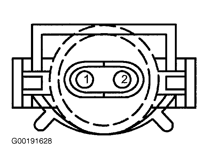
- Turn ignition switch to LOCK position. Disconnect Vehicle Speed Sensor (VSS) 2-pin harness connector C1088. VSS harness connector C1088 is located on left side of transmission tail housing. See Figure. Disconnect cruise control servo/actuator harness connector C122. Measure resistance between cruise control servo/actuator harness connector C122 terminal No. 3 and VSS harness connector C1088 terminal No. 2 (Gray/Black wire). See Fig 1 and Fig 5 . See WIRING DIAGRAMS . If resistance is 5 ohms or less, replace cruise control servo/actuator. See SERVO/ACTUATOR ASSEMBLY under REMOVAL & INSTALLATION. If resistance is greater than 5 ohms, repair open circuit in Gray/Black wire between VSS and cruise control servo/actuator. After repair, clear DTC and test system for normal operation.
 Courtesy of FORD MOTOR CO.
 Courtesy of FORD MOTOR CO.
 Courtesy of FORD MOTOR CO.