Test K: Flash With Last Switch Depressed/Dynamic Pull Occurs At Throttle - Cruise Control Inoperative
NOTE:
This test only applies to vehicle equipped with electronic instrument clusters.
NOTE:
Perform all voltage and resistance tests using a Digital Volt-Ohm Meter (DVOM) with a minimum 10-megohm input impedance, unless stated otherwise in test procedure. Use ohmmeter to isolate wiring harness shorts or opens.
- Test drive vehicle and observe speedometer operation. If speedometer operates properly, go to next step. If speedometer does not operate properly, repair speedometer as necessary. See INSTRUMENT CLUSTER - CONVENTIONAL - CROWN VICTORIA & GRAND MARQUIS or INSTRUMENT CLUSTER - ELECTRONIC - CROWN VICTORIA & GRAND MARQUIS article. After repair, test system for normal operation.
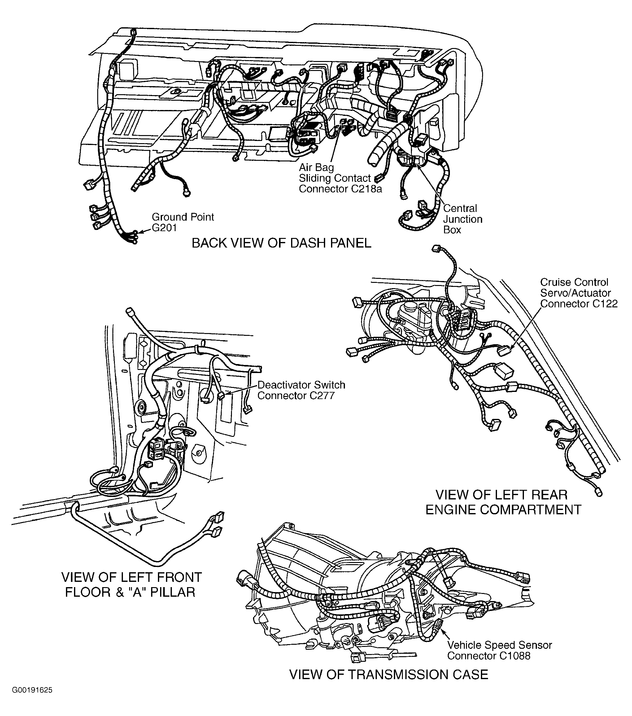
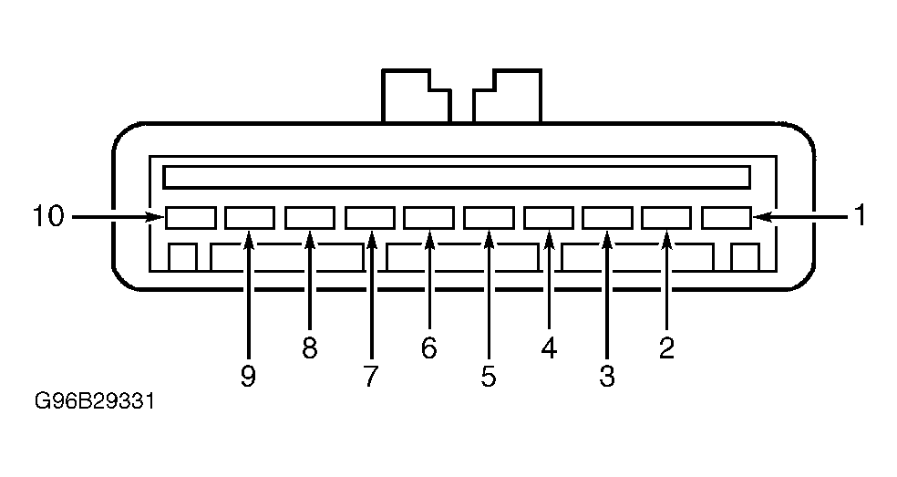
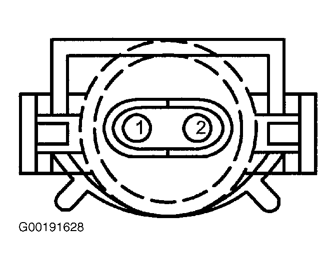
- Turn ignition switch to LOCK position. Disconnect Vehicle Speed Sensor (VSS) 2-pin harness connector C1088. VSS harness connector C1088 is located on left side of transmission tail housing. See Figure. Disconnect cruise control servo/actuator 10-pin harness connector C122. Cruise control servo/actuator harness connector C122 is located at left rear engine compartment. See Figure. Measure resistance between cruise control servo/actuator harness connector C122 terminal No. 3 and VSS harness connector C1088 terminal No. 2 (Gray/Black wire). See Figure and Figure . See WIRING DIAGRAMS . If resistance is 5 ohms or less, replace cruise control servo/actuator. See SERVO/ACTUATOR ASSEMBLY under REMOVAL & INSTALLATION. If resistance is greater than 5 ohms, repair open in Gray/Black wire between cruise control servo/actuator and VSS. After repair, clear DTC and test system for normal operation.