Wiring - Soldering And Crimping Repairs - Service Tips (05-18-7)
Publication date: 2005-09-19Reference number: 05-18-7
Supersedes refnos: 03-11-6
WIRING - SOLDERING AND CRIMPING REPAIRS - SERVICE TIPS
TECHNICAL SERVICE BULLETIN
| FORD: | 2000-2006 Crown Victoria, Focus, Mustang, Taurus; 2002-2005 Thunderbird; 2005-2006 Five Hundred, Ford GT, Freestyle; 2006 Fusion; 2000-2003 Explorer Sport, Windstar; 2000-2005 Excursion; 2000-2006 E-Series, Expedition, Explorer, F-150, F-Super Duty, Ranger; 2001-2005 Explorer Sport Trac; 2001-2006 Escape; 2004-2006 Freestar; 2005-2006 Escape Hybrid; 2000-2006 F-650, F-750; 2006 Low Cab Forward |
| LINCOLN: | 2000-2006 LS, Town Car; 2006 Zephyr; 2000-2006 Navigator; 2002-2003 Blackwood; 2003-2005 Aviator; 2006 Mark LT |
| MERCURY: | 2000-2002 Cougar; 2000-2005 Sable; 2000-2006 Grand Marquis; 2005-2006 Montego; 2006 Milan; 2000-2006 Mountaineer; 2004-2006 Monterey; 2005-2006 Mariner; 2006 Mariner Hybrid |
DESCRIPTION
WIRING - SOLDERING AND CRIMPING REPAIRS - SERVICE TIPS
ISSUE
Wire harness repairs are supported through the availability of individual components such as:
- Wire terminals with machine crimped pigtails
- Hard shell connectors
- Dual wall heat shrink tubing
- Complete, loaded, wiring pigtail kits
Some of the available tools and service parts that are helpful when performing wiring harness repairs are:
- Motorcraft Wiring Pigtail Catalog (see www.motorcraft.com for more information)
- Rotunda Wire Splice Toolkit 164-R5903 (order through 1-800-Rotunda)
- General Wire Terminal Repair Kit (order through Ford Component Sales)
Information on the pigtail and terminal repair kits can also be accessed by technicians via the PTS web site. To access on PTS:
- Select the year/model of the vehicle on the PTS home page
- Select the wiring tab
- Select the link to the pigtail or terminal repair kit at the top right of screen.
Additional service information contained in this TSB detailing wire folding, soldering, and crimping techniques may be helpful.
ACTION
REPAIR VS REPLACEMENT
The approved procedure is to repair wiring harnesses with pigtail kits, wire terminals, or hard shell connectors when available. The only exceptions to this procedure are when:
- The repair cost exceeds the cost to replace the wiring harness
- There are no component parts released to service the wiring harness
RESTRAINTS RELATED WIRING REPAIRS
If restraints connectors or wiring circuits are contained in a stand-alone harness, do not repair them; replace the restraints harness unless directed to repair the circuit by a TSB or other Ford Motor Company publication.
If restraints connectors or wiring circuits are contained in the main vehicle wiring harnesses (14401, 14A005, etc.), they should be repaired using the solder and heat-shrink repair procedure specified in this TSB. The General Wire Terminal Repair Kit contains gold plated terminated pigtails (with white insulation) and dual wall heat shrink tubing to perform these repairs. Loaded wiring pigtail kits with gold plated terminals are also available in the parts catalog.
SERVICE TIPS
Refer to applicable model year wiring diagrams for circuit information.
TWISTED WIRE CIRCUITS
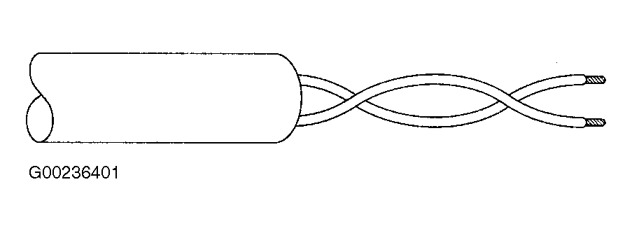
For "Twisted Wire" circuit repair (Fig 1 ), the twisting must not be disrupted for more than 2" (51 mm) Twist the repaired wires in the same direction and with the same general twist rate as the original wiring. Reapply the shielding on shielded circuits.
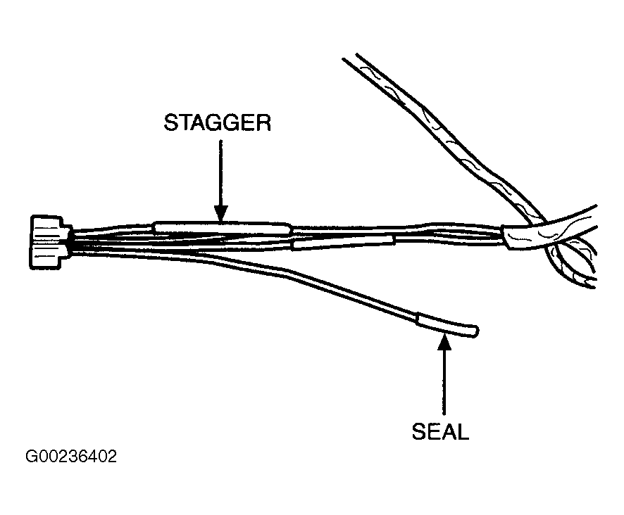
Stagger the repairs to minimize harness diameter and maintain harness length (Fig 2 ).
Any leads that are not going to be used need to be sealed with dual wall heat shrink and stowed (Fig 2 ). Silicone must not be used.
Excess wire from the harness can be folded back on itself to maintain the harness length.
Reapply any convolute and tape that was removed to make the repair.
FOR 16 AGW AND SMALLER DIAMETER WIRE
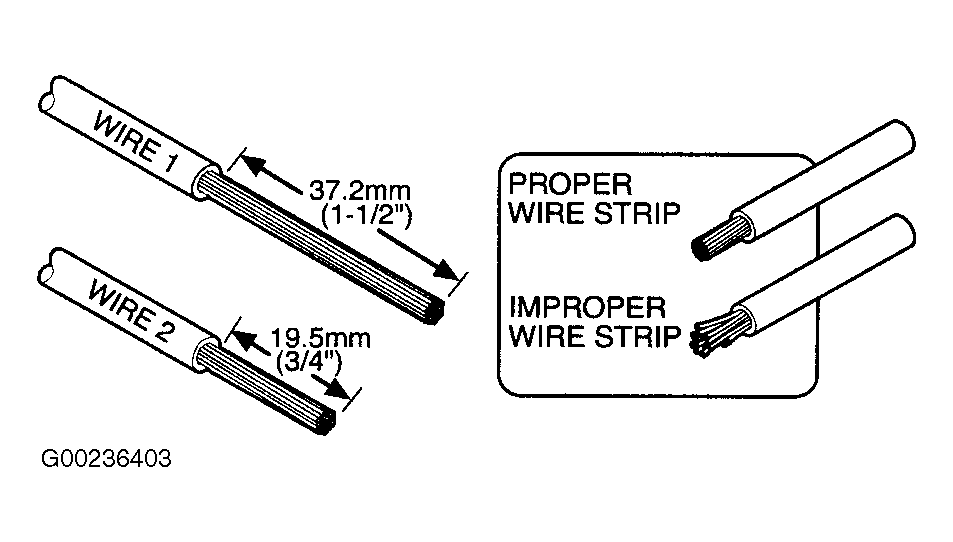
- Strip 1 1/2" (37.2mm) of insulation from Wire #1 and 3/4" (19.5mm) of insulation from Wire #2, taking care not to nick or cut wire strands (Fig 3 ). Pull wire straight from stripper. If wire is pulled at an angle, wire strands may be cut off. If more than one (1) strand is cut off during stripping, cut off the end and re-strip.
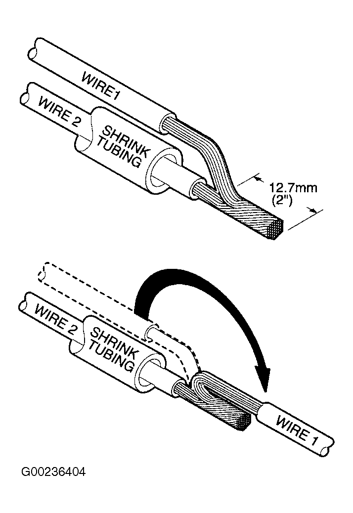
- Install heat shrink tubing at least 1" (26 mm) away from one of the stripped ends being spliced. Twist wires together. Solder wires together (Fig 4
).NOTE: USE ROSIN CORE MILDLY ACTIVATED (RMS) SOLDER. DO NOT USE ACID CORE SOLDER FOR WIRE REPAIR.
- Bend Wire #1 back in a straight line for sealing (Fig 4
). Inspect solder joint bond.NOTE: WAIT FOR SOLDER TO COOL BEFORE MOVING WIRES.
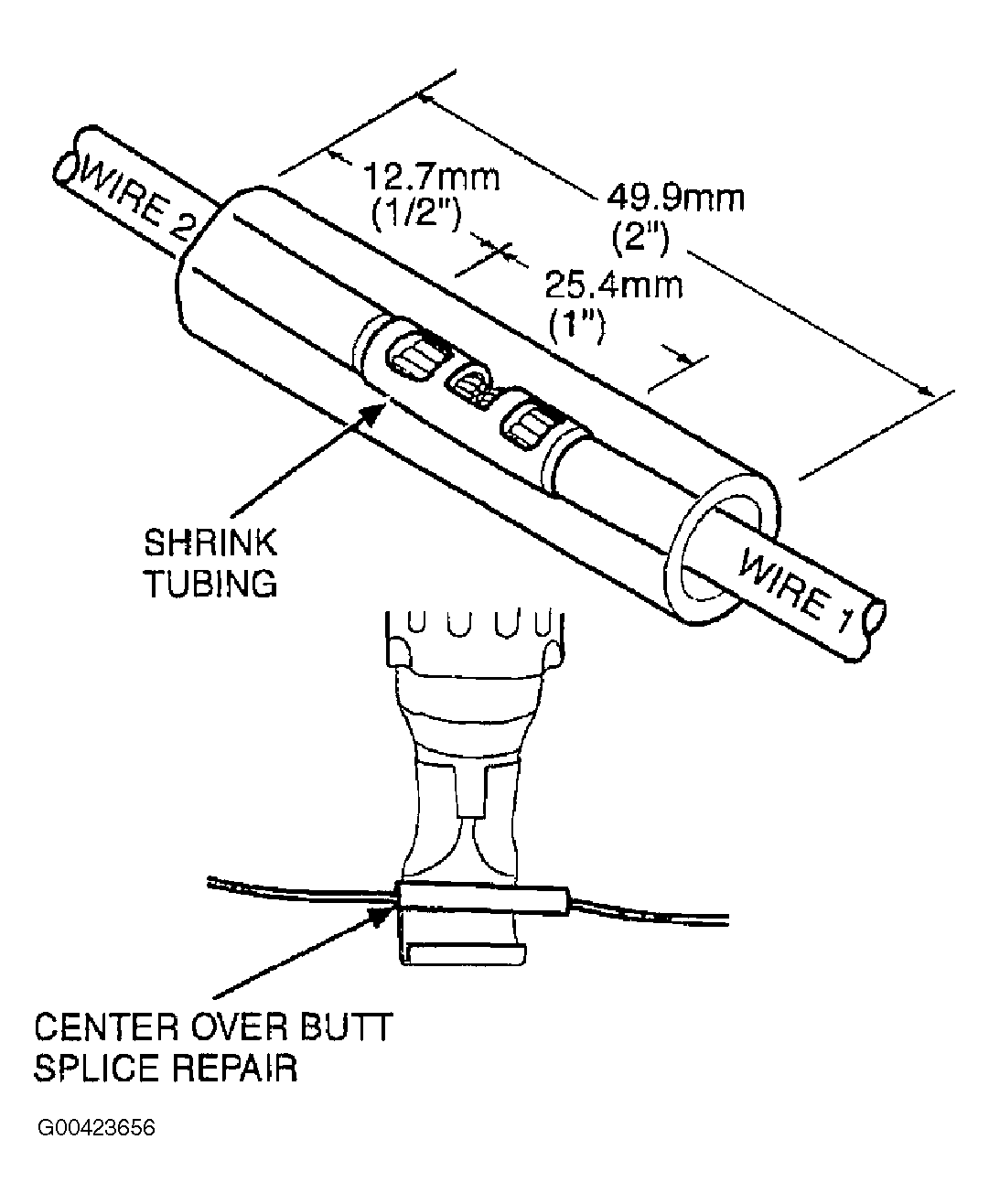
- Evenly position heat shrink tubing over wire repair (Fig 5
).NOTE: OVERLAP TUBING ON BOTH WIRES.
- Use a shielded heat gun to heat the entire length of the heat shrink tubing until the hot melt appears from both ends of the tubing. Durability of a heat shrink tubing splice is dependent on the hot melt that will appear from both ends of the tube. The hot melt forms an adhesive seal between the wire insulation and the heat shrink tubing, which prevents air and moisture from entering the solder point (Fig 5 ).
FOR 14 AGW AND LARGER DIAMETER WIRE
(EXCLUDING RESTRAINTS WIRING REPAIRS)
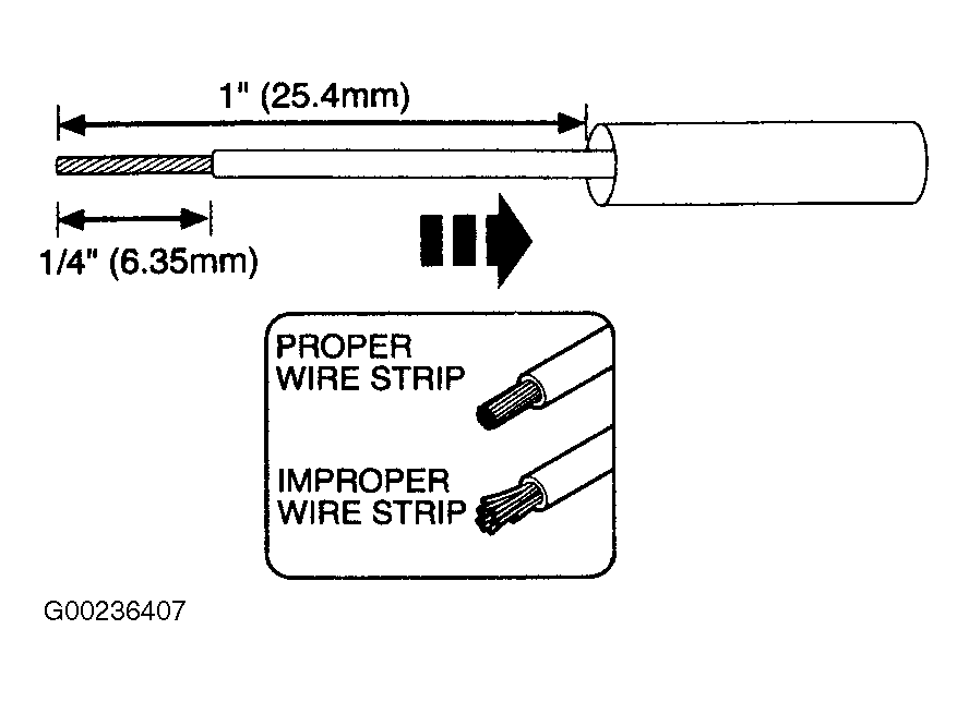
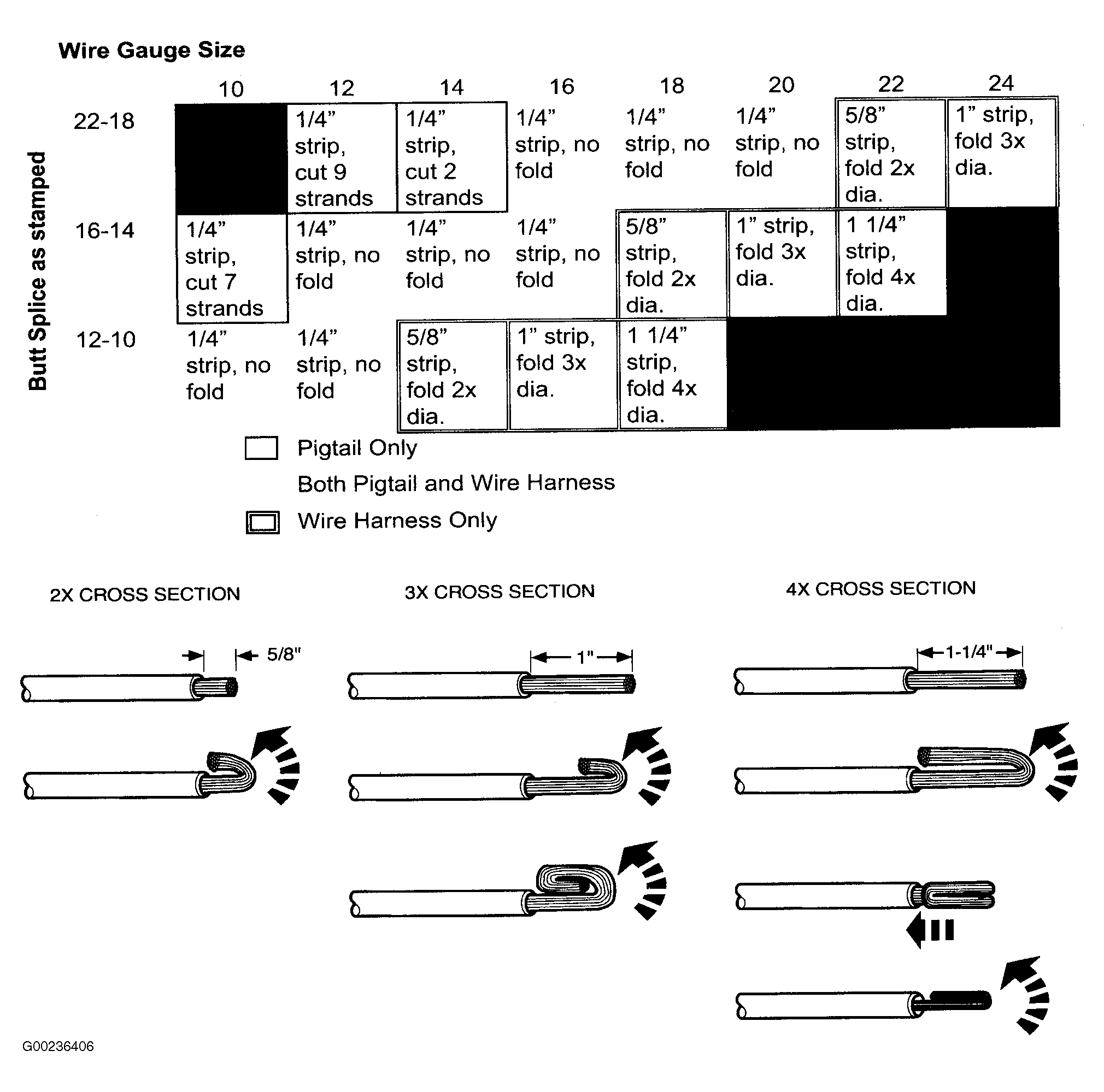
- Strip 1/4" (6.35mm) of insulation from pigtail wire end once the wire lengths are sized so repairs can be staggered. Take care not to nick or cut wire strands. Pull wire straight from stripper. If wire is pulled at an angle, wire strands may be cut off. If more than one (1) strand is cut off during stripping, cut off the end and re-strip.NOTE: THE STRIP LENGTH WILL VARY DEPENDING ON THE BUTT SPLICE AND WIRE IN HARNESS. LONGER STRIP LENGTHS ARE REQUIRED WHEN THE WIRE NEEDS TO BE FOLDED TO MATE WITH THE BUTT SPLICE. REFER TO FIGURE 10 CHART FOR STRIP LENGTHS AND FOLDING TECHNIQUES.
- Slide heat shrink tubing onto one (1) of the wire ends to be crimped, must be at least 1" (25.4mm) away from stripped end (Fig 6 ).
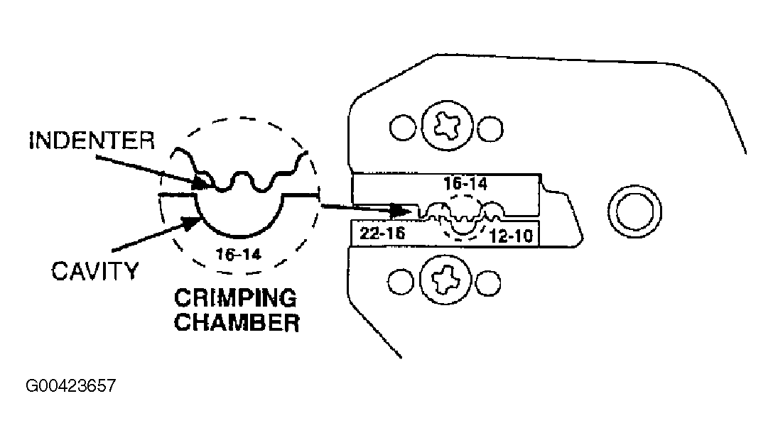
- Identify the appropriate crimping chamber of the Rotunda 164-R5901 Pro-Crimper (or equivalent) by matching the wire size on the dies with the wire size stamped on the butt splice (Fig 7 ). Hold the crimping tool so the identified wire sizes are facing you. Squeeze tool handles together until the ratchet releases, then allow the jaws of the tool to open fully.
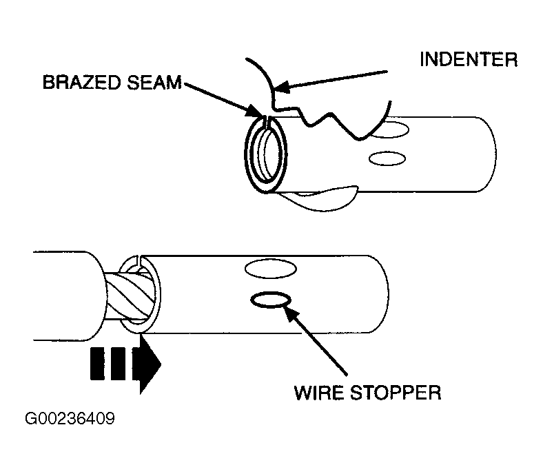
- Center one (1) end of the butt splice on the appropriate crimping chamber. If visible, be sure to place the brazed seam of the butt splice toward the indenter (Fig 8 ).
- Hold the butt splice in place and squeeze the tool handles together until the ratchet engages sufficiently to hold the butt splice in position (typically one (1) or two (2) clicks). DO NOT deform the butt splice.
- Insert stripped wire into the butt splice, making sure the insulation on wire does not enter the butt splice (Fig 8 ).
- Holding the wire in place, squeeze tool handles together until ratchet releases. Allow tool handles to open, then remove crimped butt splice.
- To crimp the other half of the splice, reposition the un-crimped wire barrel in the same crimping chamber, and repeat Steps 3-8. If splice cannot be turned for crimping the other half, turn the tool around.
- Check for acceptable crimp.
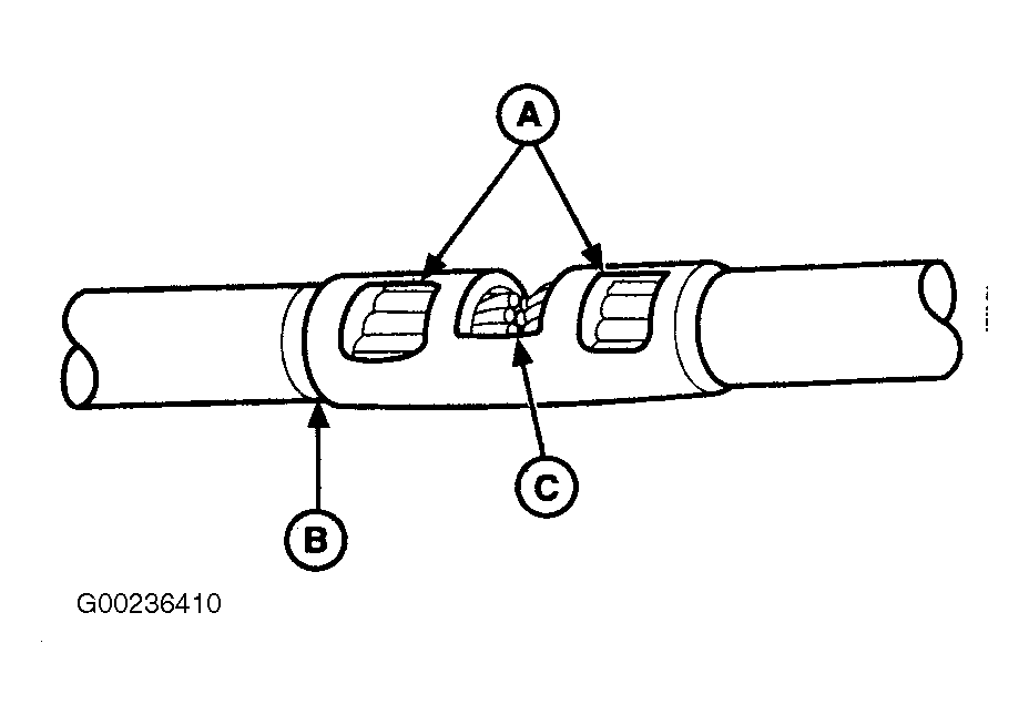
- Crimp should be centered on each end of the butt splice. It is acceptable for crimp to be slightly off center, but not off the end of the butt splice (Fig 9 -a).
- Wire insulation does not enter butt splice. Wire is flush with or extends slightly beyond end of butt splice (Fig 9 -b).
- Wire is visible through inspection hole of splices (Fig 9 -c).
- Evenly position heat shrink tubing over wire repair (Fig 5
).NOTE: OVERLAP TUBING ON BOTH WIRES.
- Use a shielded heat gun to heat the entire length of the heat shrink tubing until the hot melt appears from both ends of the tubing. Durability of a heat shrink tubing splice is dependent on the hot melt that will appear from both ends of the tube. The hot melt forms an adhesive seal between the wire insulation and the heat shrink tubing, which prevents air and moisture from entering the solder point (Fig 5 ).
WARRANTY INFORMATION
WARRANTY STATUS: Information Only.