Test B: Rear Window Defogger Inoperative
NOTE:
Perform all voltage and resistance tests using a Digital Volt-Ohm Meter (DVOM) with a minimum 10-megohm input impedance, unless stated otherwise in test procedure. Use ohmmeter to isolate wiring harness shorts or opens.
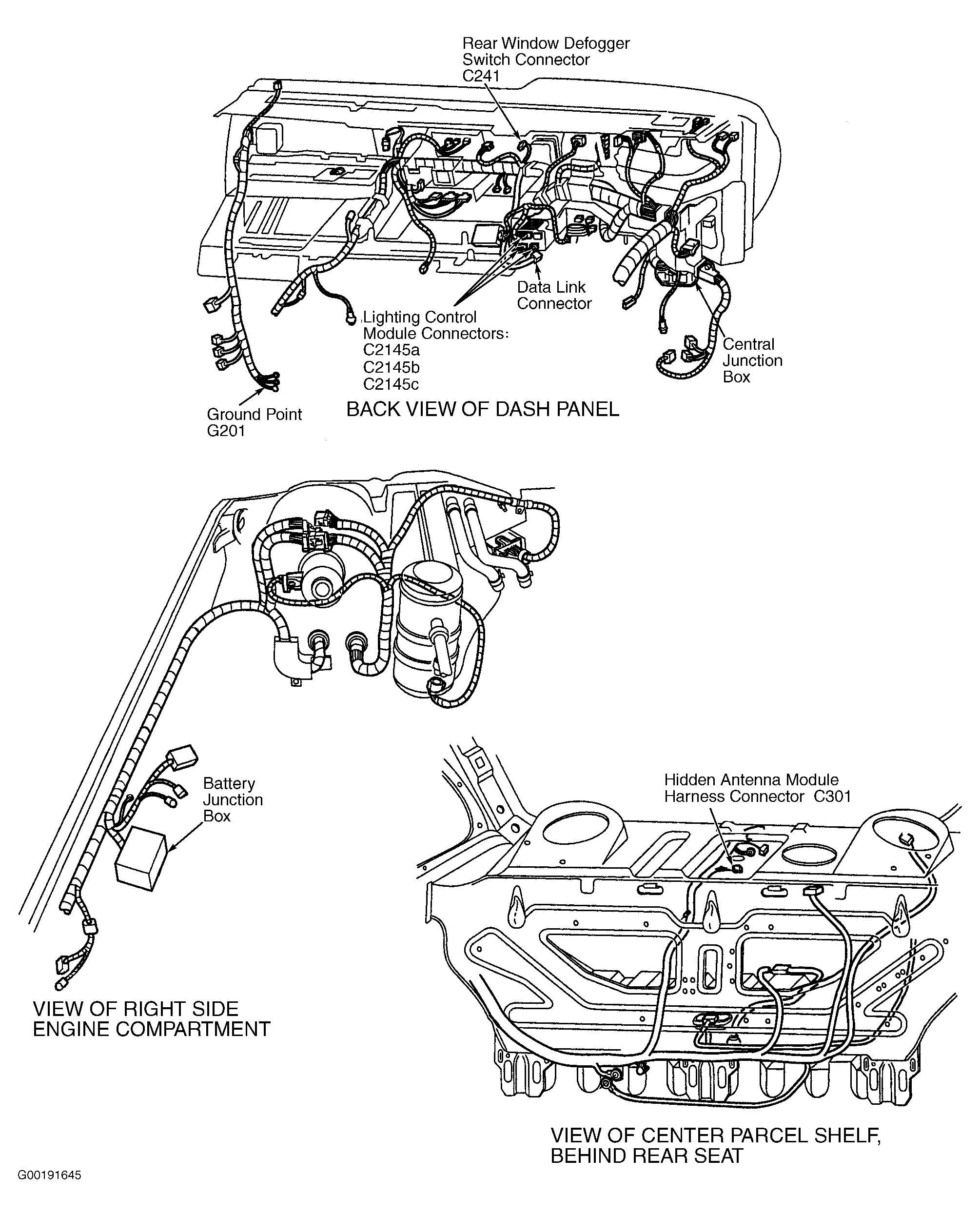
- Turn ignition switch to LOCK position. Connect Worldwide Diagnostic System (WDS) tester or New Generation Star (NGS) tester to Data Link Connector (DLC), located below left side of instrument panel. See Figure. Turn ignition switch to RUN position. Using WDS or NGS tester, perform self-test and retrieve DTCs. If DTC B1345 is retrieved, go to next step. If DTC B1345 is not retrieved, go to step 4.
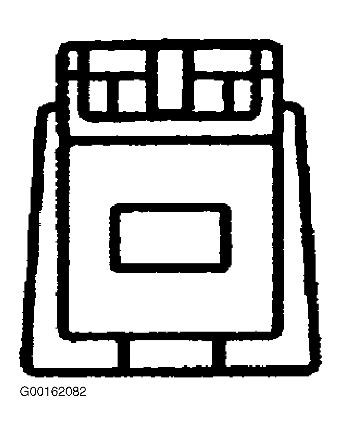
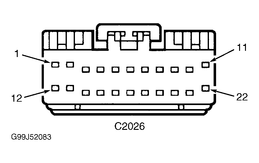
- Turn ignition switch to LOCK position. Disconnect Lighting Control Module (LCM) 22-pin harness connector C2145a, located behind left center side of instrument panel. See Figure. Measure resistance between ground and LCM harness connector C2145a terminal No. 18 (Dark Blue/Orange wire). See Fig 1. See WIRING DIAGRAMS . If resistance is 10 k/ohms or less, go to next step. If resistance is greater than 10 k/ohms, clear DTCs and repeat self-test. If DTC B1345 still exists, replace LCM. See LIGHTING CONTROL MODULE under REMOVAL & INSTALLATION. After repair, test system for normal operation.
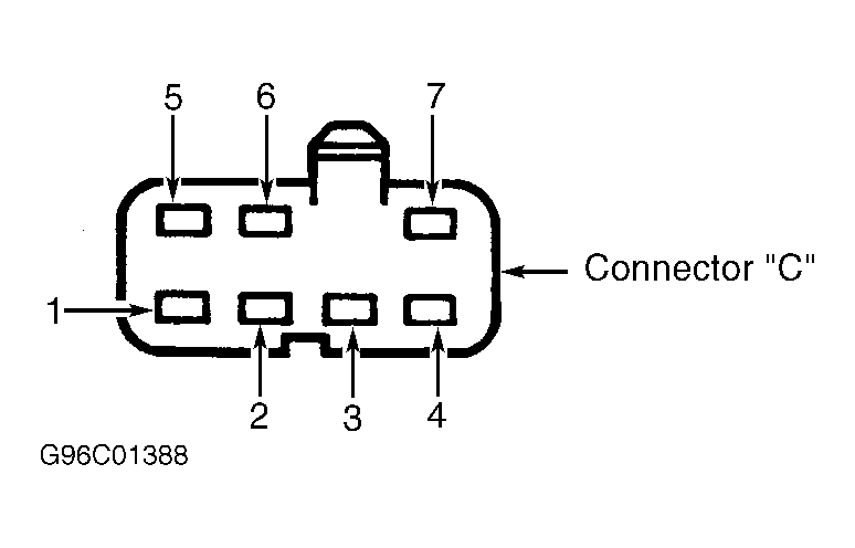
- Turn ignition switch to LOCK position. Disconnect rear window defogger switch 7-pin harness connector C241, located behind top center of dash panel. See Figure. Measure resistance between ground and LCM harness connector C2145a terminal No. 18 (Dark Blue/Orange wire). See Fig 1. See WIRING DIAGRAMS . If resistance is less than 10 k/ohms, repair short to ground in Dark Blue/Orange wire between LCM and rear window defogger switch. If resistance is greater than 10 k/ohms, replace rear window defogger switch. After repair, clear DTC and test system for normal operation.
- Leave ignition switch in RUN position. Press rear defogger switch to ON position. Using WDS or NGS tester, trigger rear window defogger switch status PID RDEF_SW. If PID indicates rear window defogger switch is NOTACT, go to next step. If PID indicates rear window defogger switch is ACTIVE, go to step 8.
- Turn ignition switch to LOCK position. Disconnect Lighting Control Module (LCM) 22-pin harness connector C2145a, located behind left center side of instrument panel. See Figure. Measure resistance between ground and LCM harness connector C2145a terminal No. 18 (Dark Blue/Orange wire). See Fig 1. See WIRING DIAGRAMS . Press rear window defogger switch to ON position. If resistance is greater than 5 ohms, go to next step. If resistance is 5 ohms or less, replace LCM. See LIGHTING CONTROL MODULE under REMOVAL & INSTALLATION. After repair, test system for normal operation.
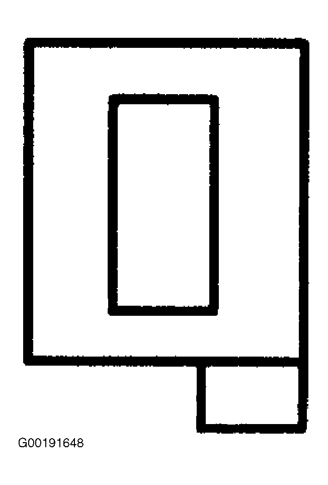
- Disconnect rear window defogger switch 7-pin harness connector C241, located behind top center of dash panel. See Figure. Measure resistance between ground and rear window defogger switch harness connector C241 terminal No. 2 (Black wire). See Fig 2. See WIRING DIAGRAMS . If resistance is 5 ohms or less, go to next step. If resistance is greater than 5 ohms, repair open circuit in Black wire between rear window defogger switch and ground point located behind right rocker panel. See Figure. After repair, test system for normal operation.
- Measure resistance between LCM harness connector C2145a terminal No. 18 and rear window defogger switch harness connector C241 terminal No. 1 (Dark Blue/Orange wire). See Fig 1 and Fig 2 . See WIRING DIAGRAMS . If resistance is 5 ohms or less, replace rear window defogger switch. If resistance is greater than 5 ohms, repair open circuit in Dark Blue/Orange wire between LCM and rear window defogger switch. After repair, clear DTC and test system for normal operation.
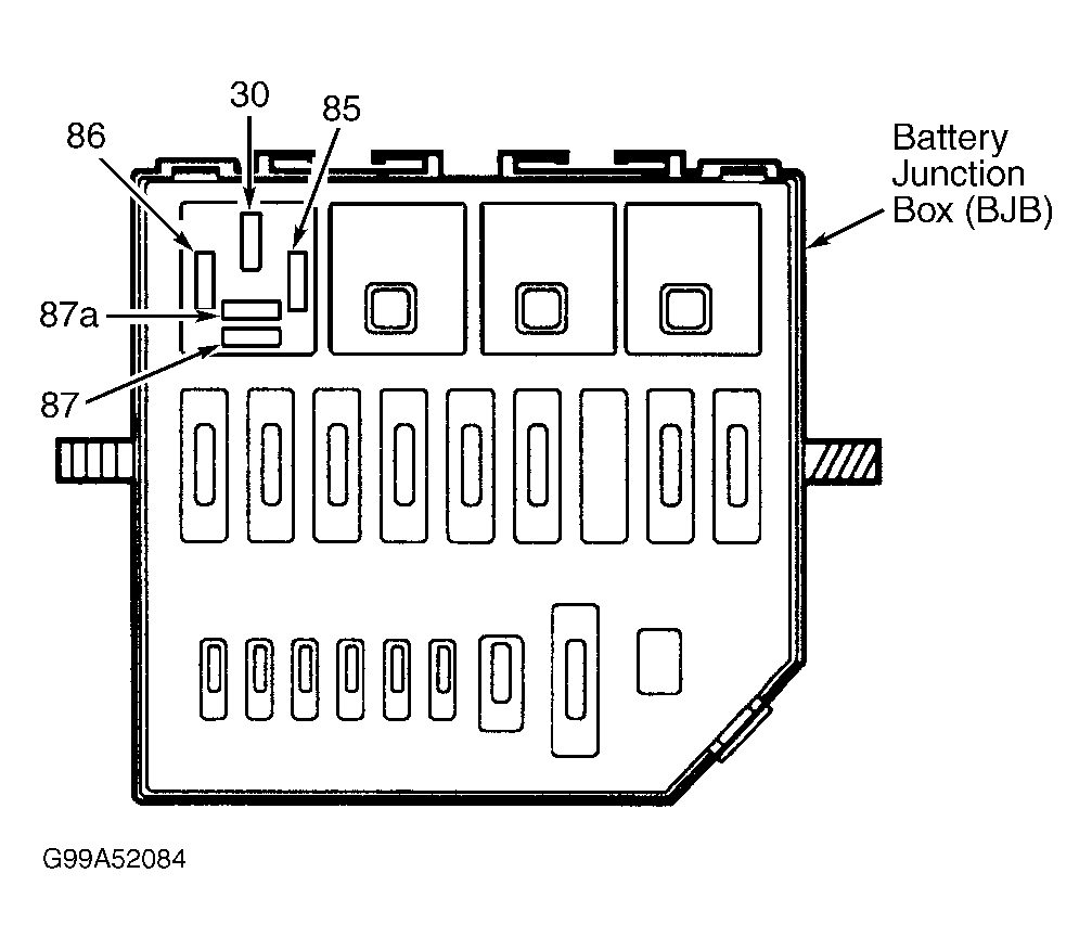
- Turn ignition switch to LOCK position. Remove rear window defogger relay from Battery Junction Box (BJB), located at right front of engine compartment. See Figure. Using WDS or NGS tester, access LCM active command HEATED BACKLIGHT. Measure resistance between ground and rear window defogger relay harness connector C1099 cavity terminal No. 86 (Gray/Light Blue wire). See Fig 3. Trigger RLY CNTRL ON. If resistance is greater than 5 ohms, go to next step. If resistance is 5 ohms or less, go to step 10.
- Ensure ignition switch is in LOCK position. Disconnect Lighting Control Module (LCM) 22-pin harness connector C2145a. LCM is located behind left center side of instrument panel. See Figure. Measure resistance between LCM harness connector C2145a terminal No. 12 and rear window defogger relay harness connector C1099 cavity terminal No. 86 (Gray/Light Blue wire). See Fig 1 and Fig 3 . See WIRING DIAGRAMS . If resistance is 5 ohms or less, replace LCM. See LIGHTING CONTROL MODULE under REMOVAL & INSTALLATION. If resistance is greater than 5 ohms, repair open circuit in Gray/Light Blue wire between LCM and BJB. After repair, clear DTC and test system for normal operation.
- Measure voltage between ground and rear window defogger relay harness connector C1099 cavity terminals No. 30 and 85 (Black wires). See WIRING DIAGRAMS . If both voltage readings are greater than 10 volts, go to next step. If either or both voltage readings are 10 volts or less, repair open circuit in appropriate Black wire between rear window defrost relay and BJB fuse No. 14. After repair, test system for normal operation.
- Install rear window defogger relay back into BJB. Disconnect rear window defogger grid power supply single harness connector, located on rear window. Using WDS or NGS tester, access LCM active command HEATED BACKLIGHT. Measure voltage between ground and rear window defogger grid power supply single harness connector terminal. See Fig 4. See WIRING DIAGRAMS . Using WDS or NGS tester, trigger RLY CNTRL ON. If voltage is greater than 10 volts, go to next step. If voltage is 10 volts or less, go to step 13. After repair, test system for normal operation.
- Ensure ignition switch is in LOCK position. Disconnect rear window defogger grid ground supply single pin harness connector, located on rear window. Measure resistance between ground and rear window defogger grid ground supply harness connector terminal. See Fig 4. See WIRING DIAGRAMS . If resistance is 5 ohms or less, test rear window defogger grid. See GRID FILAMENT TEST under COMPONENT TESTS. If resistance is greater than 5 ohms, repair open circuit in Black wire between hidden antenna module and rear window defogger grid. After repair, clear DTC and test system for normal operation.
- Ensure ignition switch is in LOCK position. Disconnect hidden antenna module single harness connector C301, located at center of parcel shelf, behind rear seat. See Figure. Using WDS or NGS tester, access LCM active command HEATED BACKLIGHT. Measure voltage between ground and hidden antenna module harness connector C301. (Brown/Light Blue wire). See Fig 5. See WIRING DIAGRAMS . Trigger RLY CNTRL ON. If voltage is 10 volts or less, go to next step. If voltage is greater than 10 volts, replace hidden antenna module. After repair, test system for normal operation.
- Ensure ignition switch is in LOCK position. Remove rear window defogger relay from BJB. Measure resistance between hidden antenna module harness connector C301 and rear window defogger relay harness connector C1099 cavity terminal No. 87 (Brown/Light Blue wire). See Fig 3 and Fig 5
. See WIRING DIAGRAMS . If resistance is 5 ohms or less, replace rear window defogger relay. If resistance is greater than 5 ohms, repair open circuit in Brown/Light Blue wire between hidden antenna module and rear window defogger relay. After repair, clear DTC and test system for normal operation.
 Courtesy of FORD MOTOR CO.
 Courtesy of FORD MOTOR CO.