Safety Recall 02S39 - Natural Gas Vehicles (NGV) - "T" Fitting Replacement (02S39)
Publication date: 2002-08-01Reference number: 02S39
SAFETY RECALL 02S39 - NATURAL GAS VEHICLES (NGV) - "T" FITTING REPLACEMENT
SERVICE CAMPAIGN BULLETIN
| FORD: | 2002 Crown Victoria Natural Gas |
SAFETY RECALL 02S39
SUBJECT
Safety Recall 02S39: Certain 2002 Model Year Crown Victoria Natural Gas Vehicles (NGV) - "T" Fitting Replacement
AFFECTED VEHICLES
Certain 2002 model year Crown Victoria NGV vehicles built at the St. Thomas Assembly Plant from Job One to Job Last.
SAFETY CONCERN
On some of the affected vehicles, a "T" fitting that connects fuel tanks three and four may develop a leak when solenoid valves are energized, such as when the ignition switch is in the ON position or during refueling. The leak can be easily heard and will stop leaking when the ignition key is turned to the OFF position or the refueling process is terminated. A gas leak of sufficient quantity concentrated in an area to create a combustible mixture and in the presence of an ignition source could result in a fire.
SERVICE ACTION
The Ford Certified NGV dealer will replace the "T" fitting on number 4 fuel tank with a redesigned "T" fitting, tighten the "T" fitting jam nut to 43 Nm (32 lb-ft), test the fitting for leakage and clear diagnostic codes.
PLEASE NOTE
Correct all vehicles in stock before delivery. Federal law requires dealers to complete any outstanding safety recall service before a new vehicle is delivered to the buyer or lessee. Violation of this requirement by a dealer could result in a civil penalty of up to $5,000 per vehicle.
ATTACHMENTS
- Attachment I: Administrative Information
- Attachment II: Labor Allowances and Parts Ordering Information
- Attachment III: Technical Information
- Customer Notification Letter(s)
QUESTIONS?
- Claims Information:.........................................1-800-423-8851
- Online Involved Unit Listings ...........................1-800-555-9601
- Other (Dealer Only) Recall Questions:................1-800-325-5621
ATTACHMENT I
Safety Recall 02S39
Certain 2002 Model Year Crown Victoria Natural Gas Vehicles (NGV)
"T" Fitting Replacement
OASIS
You must use OASIS to determine if a vehicle is eligible for this recall.
PROMPTLY CORRECT
Promptly correct all affected vehicles on your dealer Online Involved Unit Listing available on QCDealer.com. Also, correct other affected vehicles identified in OASIS which are brought to your dealership.
DEALER-OWNER CONTACT
Immediately contact any of your affected owners whose names are not on your VIN list but identified in OASIS. Give the owner a copy of the Owner Letter and schedule a service date.
REGIONAL CONTACT
Advise regional office if an owner:
- cannot be contacted.
- does not make a service date.
CLAIMS PREPARATION AND SUBMISSION
- Enter claims using DWE.
- Refer to ACESII manual for claims preparation and submission information.
OWNER REFUNDS
Ford Motor Company will only refund owner-paid repairs applicable to this recall which were made before the date of the Owner Letter (or after the date of the Owner Letter if an emergency repair was made away from the servicing dealer). Refer to ACESII manual for refund information.
RENTAL CARS
The use of rental vehicles is not authorized for this program.
ATTACHMENT II
Safety Recall 02S39
Certain 2002 Model Year Crown Victoria Vehicles Natural Gas Vehicles (NGV)
"T" Fitting Replacement
LABOR ALLOWANCES
| Description | Labor Operation | Labor Time |
|---|---|---|
| Remove #4 fuel tank "T" fitting, install and Torque new "T" fitting, check fitting for leakage, and clear diagnostic codes. | 02S39B | 1.6 Hrs. |
| Administrative Allowance | Misc. Expense Code "ADMIN" | 0.1 Hour |
PARTS REQUIREMENTS
Parts will be direct shipped to Ford Certified NGV dealers for this recall. Only Ford Certified NGV dealers will be seed stocked and should receive their individual seed stock allocations one week after launch. Only Ford Certified NGV dealers should order this part.
All orders until October 13, 2002: Call 1-800-325-5621
All orders after October 14, 2002: Normal Order Process
| Part Number | Description | Quantity |
|---|---|---|
| 2W7Z-9C116-BA | Valve Assembly | 1 |
ORDER INFORMATION
The DOR/COR for this program is 50285 . This number identifies parts ordered for this recall through the Special Service Support Center (1-800-325-5621).
PARTS RETENTION
Follow the provisions of the Warranty and Policy Manual for "Parts Retention and Return Procedures".
DEALER PRICE
For latest prices, refer to DOES II or updated price book.
EXCESS STOCK RETURN
Excess stock returned for credit must have been purchased from Ford Customer Service Division in accordance with Policy Procedure Bulletin 4000.
ATTACHMENT III
NATURAL GAS VEHICLE (NGV) T-FITTING REPLACEMENT
AFFECTED VEHICLES
CERTAIN 2002 MODEL YEAR CROWN VICTORIA NATURAL GAS VEHICLES (NGV)
OVERVIEW
A new updated T-fitting must be installed on the No. 4 fuel tank. The valves on all of the fuel tanks must be locked down and any residual fuel pressure purged from the fuel lines prior to installing the new T-fitting. The proper installation and tightening of the T-fitting is critical to ensure a leakproof repair. Therefore, you should read this document completely, including all notes, cautions and warnings before beginning work on the vehicle.
FUEL SYSTEM PRESSURE RELIEF
- Install a memory saver, then disconnect the battery negative cable.
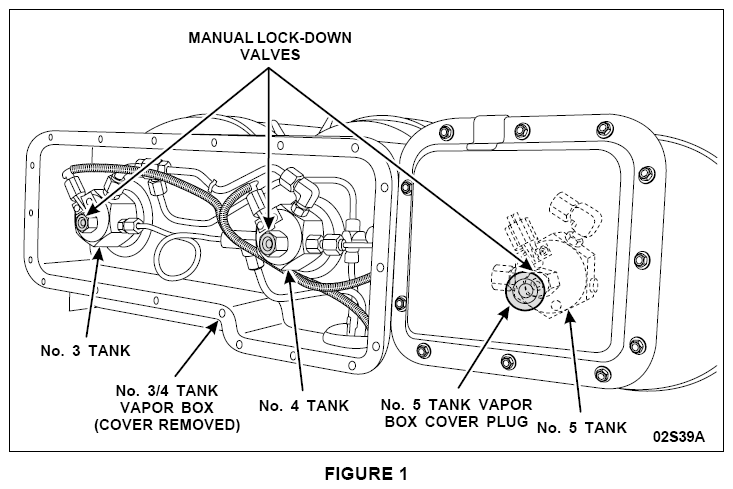
- Remove the cover from the No. 3/4 tank vapor box. See Figure 1.
- Close each manual lock-down valve on the No. 3 and No. 4 tanks. Tighten each lock-down valve to 8 Nm (71 lb-in). See Figure 1.
- On vehicles equipped with a No. 5 tank, remove the access plug from the No. 5 tank vapor box cover. Using a long ball end hex bit, close the manual lock-down valve on the No. 5 tank. Tighten the lock-down valve to 8 Nm (71 lb-in). See Figure 1.
- Raise the vehicle on a hoist.
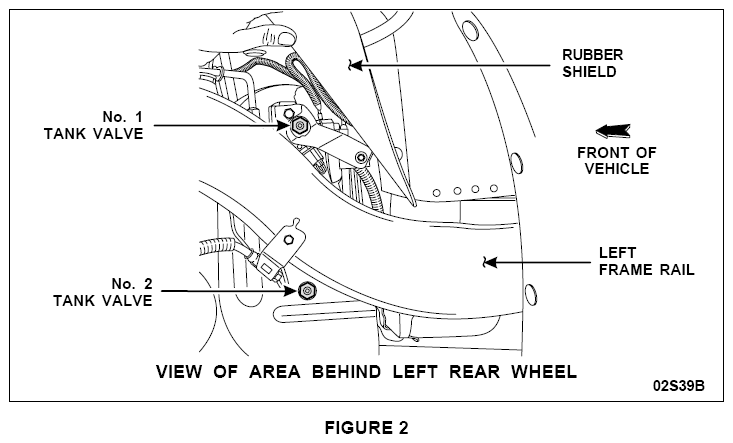
- Remove the access plug from the No. 2 tank cover (located behind the left rear wheel). Close the manual lock-down valve on the No. 2 tank. Tighten the lock-down valve to 8 Nm (71 lb-in). See Figure 2.
- Remove two (2) pushpins and position the rubber shield (located above left rear frame rail) for the No. 1 tank out of the way. Close the manual lock-down valve on the No. 1 tank. Tighten the lock-down valve to 8 Nm (71 lb-in). See Figure 2.
- Lower the vehicle.
- Using the Rotunda Natural Gas (NGV) Pressure Test and Venting Kit (134-00114), relieve the fuel system pressure as follows.
- Connect the grounding cable from the engine fuel supply manifold to the shop ground rod.
- Connect the fuel rail pressure tester to the fuel supply manifold schrader valve.
- Connect the venting hose assembly from the fuel rail pressure tester to the shop vent stack.
- Slowly open the bleed valve on the fuel rail pressure tester and allow the contents of the fuel lines to vent to the atmosphere for one minute.
- Close the bleed valve and remove the fuel rail pressure tester, venting hose assembly and grounding cable.
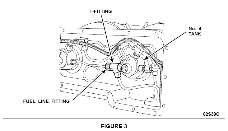
- Slightly loosen the fuel line fitting on the No. 4 tank T-fitting to allow any residual pressure to escape from the system. See Figure 3.
T-FITTING REPLACEMENT
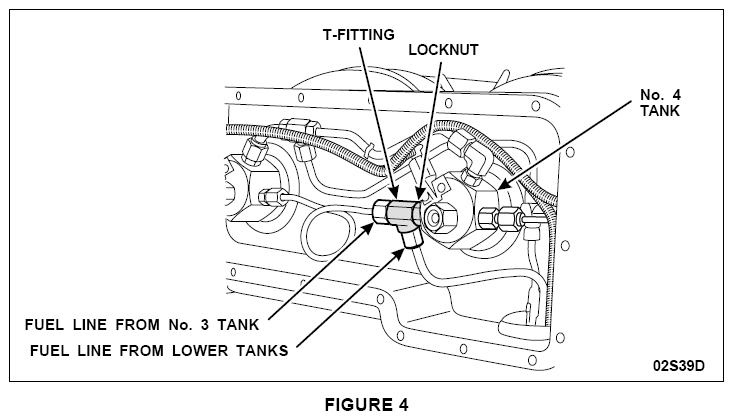
- Disconnect the two (2) fuel lines (from lower tanks and No. 3 tank) from the T-fitting on the No. 4 tank. See Figure 4.
- Loosen the locknut on the T-fitting, then remove and discard the T-fitting. See Figure 4.
- WARNING:
DO NOT USE ANY SOLVENTS OR COMPRESSED AIR TO CLEAN ANY COMPONENTS OF THE NGV FUEL SYSTEM. SOLVENTS MAY DETERIORATE THE O-RINGS AND AFFECT THEIR SEALING CAPABILITIES. COMPRESSED AIR AND NATURAL GAS FORM A HIGHLY COMBUSTIBLE MIXTURE.
Clean the T-fitting mounting surface on the No. 4 tank with a clean dry cloth.
- CAUTION:
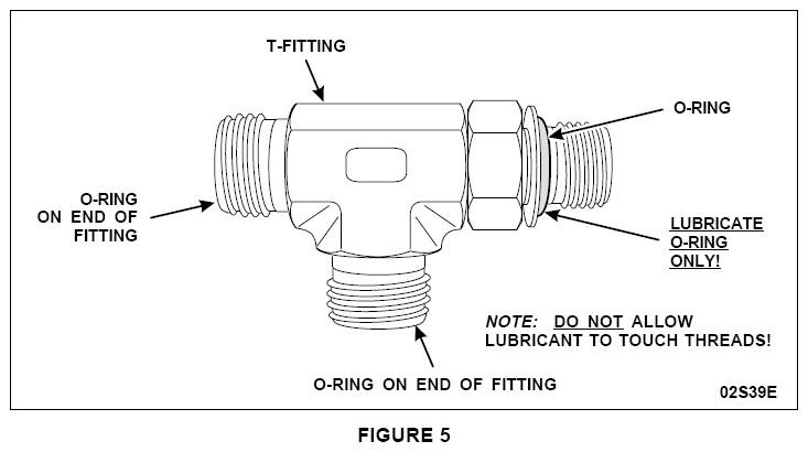
Apply the lubricant to the O-rings sparingly. Do NOT allow excess lubricant to touch the threads of the T-fitting. Any lubricant on the threads will adversely affect the tightening properties of the locknut and may damage the T-fitting during the tightening of the locknut.
Lubricate the O-rings on the new T-fitting with Motorcraft Super Premium SAE 5W-20 Motor Oil X0-5W20-QSP or equivalent meeting Ford specification WSS-M2C153-H. See Figure 5.
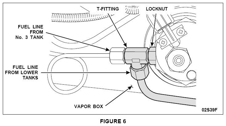
- Thread the new T-fitting into the No. 4 tank by hand until the O-ring makes contact. Continue tightening until the fuel line from the lower tanks is properly oriented with the new T-fitting. See Figure 6.
- CAUTION:
The fuel lines must not contact the vapor box when they are in the installed position. If the fuel line contacts the vapor box, friction between the two components may result in wear of the fuel line and/or provide an ignition source for any vapors in the box.
Connect the fuel line from the lower tanks to the new T-fitting. Make sure the fuel line is not contacting the vapor box and adjust the position of the fuel line and/or T-fitting if necessary. Snug up the fuel line with a short open end wrench (do not final tighten at this time). See Figure 6.
- Connect, but do not tighten, the fuel line from the No. 3 tank to the T-fitting. See Figure 6.
- CAUTION:
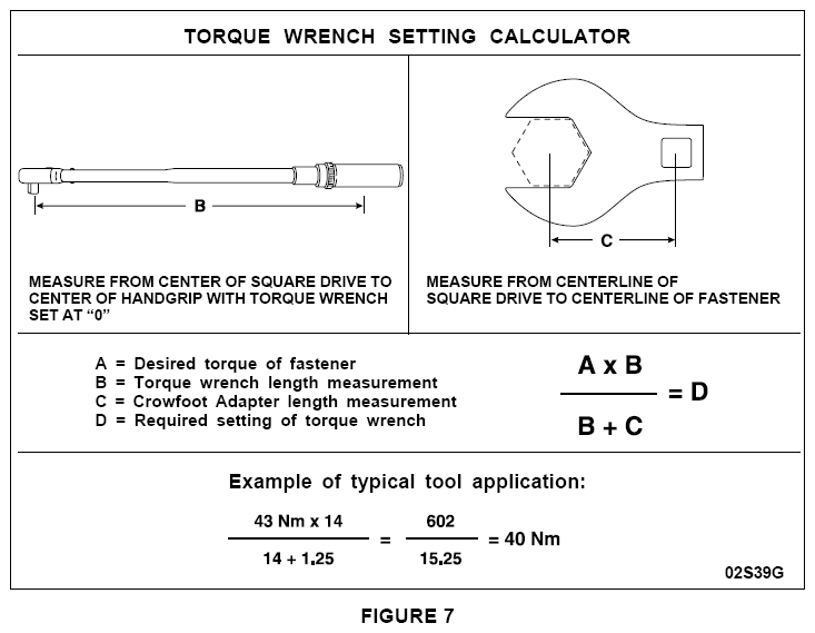
The fuel lines must not contact the vapor box when they are in the installed position. If necessary, adjust the position of the T-fitting and/or the fuel line while tightening the components.CAUTION: The use of a crow foot adapter on a torque wrench increases the length of the tool and changes the actual torque value. To achieve the proper torque on the fastener, you must use the formula supplied in this document to calculate the proper setting for the torque wrench/crow foot you are using.
Using the formula in Figure 7, calculate the proper torque setting, then tighten the T-fitting locknut and fuel line connections as follows.
- Raise the vehicle on a hoist.
- Open the manual lock-down valve on the No. 1 tank. Tighten the lock-down valve in the open position to 8 Nm (71 lb-in). Reposition the rubber shield and install the two (2) pushpins.
- Open the manual lock-down valve on the No. 2 tank. Tighten the lock-down valve in the open position to 8 Nm (71 lb-in). Install the access plug into the No. 2 tank cover.
- Lower the vehicle.
- On vehicles equipped with a No. 5 tank, open the manual lock-down valve. Tighten the lock-down valve in the open position to 8 Nm (71 lb-in). Install the access plug into the No. 5 tank vapor box.
- Open each manual lock-down valve on the No. 3 and No. 4 tanks. Tighten each lock-down valve in the open position to 8 Nm (71 lb-in).
- Connect the battery negative cable, then remove the memory saver.
- Turn the ignition to the RUN position to pressurize the fuel lines.
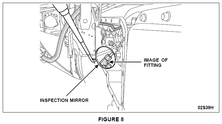
- Leak check the repair by applying a soapy water solution to the T-fitting connections. Use of an inspection mirror will be necessary to view the connections. If any soap bubbles form, this indicates a leak at the connection. See Figure 8.
- Install the cover on the No. 3/4 tank vapor box. Tighten the bolts to 9 Nm (80 lb-in).
- Clear the diagnostic trouble codes.