LEMON Manuals: Even more car manuals for everyone: 1960-2025
Home >> Ford >> 2002 >> Crown Victoria Base, 4.6 9 >> Repair and Diagnosis (Single Page) >> Accessories & Equipment >> Interior/Exterior Trim >> Instrument Panel & Console >> Removal & Installation >> Instrument Panel >> Installation

Instrument Panel: Installation

CAUTION: Electronic modules are sensitive to static electrical charges. Avoid exposing any modules to static electrical charges, as this may cause damage to the modules.
    NOTE: Two technicians are needed to carry out this step.
    NOTE: Feed the LH wiring harness through the dash panel while carrying out this step.
    NOTE: Make sure the center instrument panel locator is engaged at the cowl top.
  1. Install the instrument panel into the vehicle.
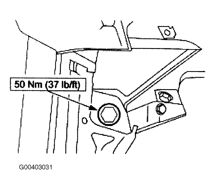
  2. Install the lower LH instrument panel cowl side bolt.
    Fig 1: Installing Lower LH Instrument Panel Cowl Side Bolt
    G00403031Courtesy of FORD MOTOR CO.
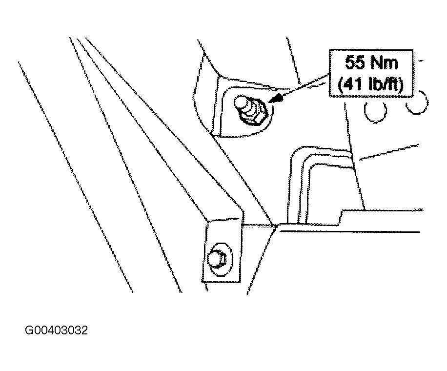
  3. Install the upper LH instrument panel cowl side nut.
    Fig 2: Installing Upper LH Instrument Panel Cowl Side Nut
    G00403032Courtesy of FORD MOTOR CO.
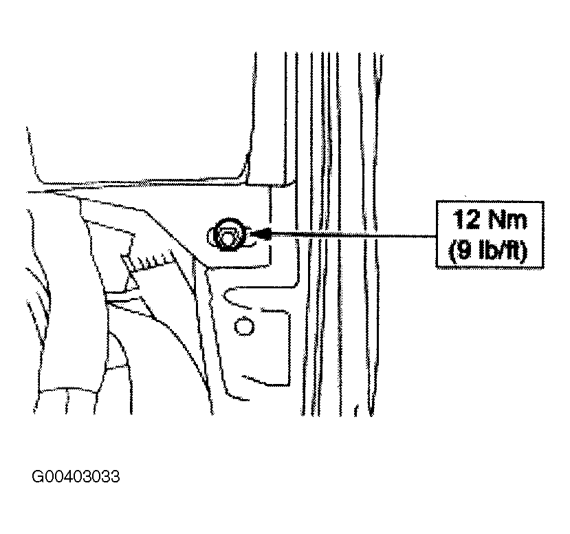
  4. Install the RH instrument panel cowl side nut.
    Fig 3: Installing RH Instrument Panel Cowl Side Nut
    G00403033Courtesy of FORD MOTOR CO.
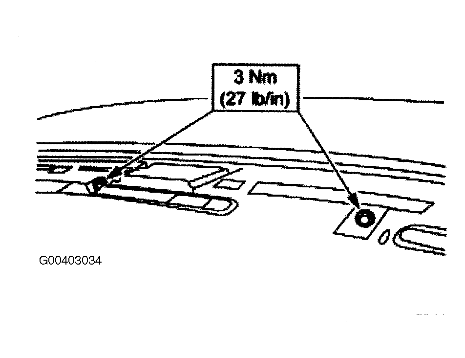
  5. Install the three instrument panel cowl top screws.
    Fig 4: Installing Instrument Panel Cowl Top Screws
    G00403034Courtesy of FORD MOTOR CO.
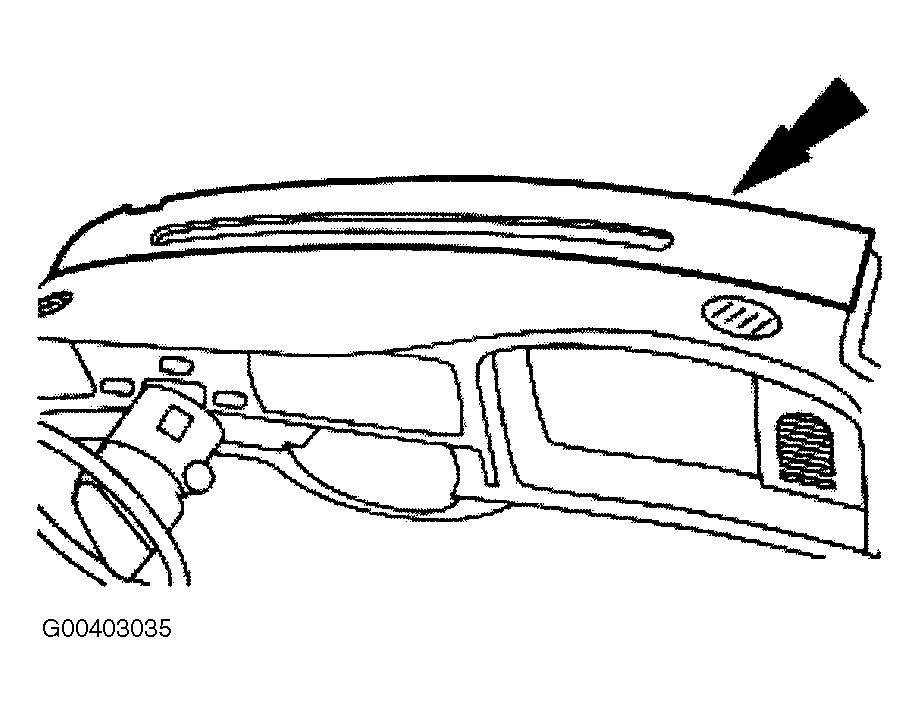
  6. Install the defroster opening grille.
    • If equipped, connect the electrical connectors.
    Fig 5: Installing Defroster Opening Grille
    G00403035Courtesy of FORD MOTOR CO.
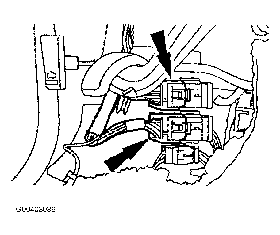
  7. Connect the LH wiring harness connectors.
    Fig 6: Installing LH Wiring Harness Connectors
    G00403036Courtesy of FORD MOTOR CO.
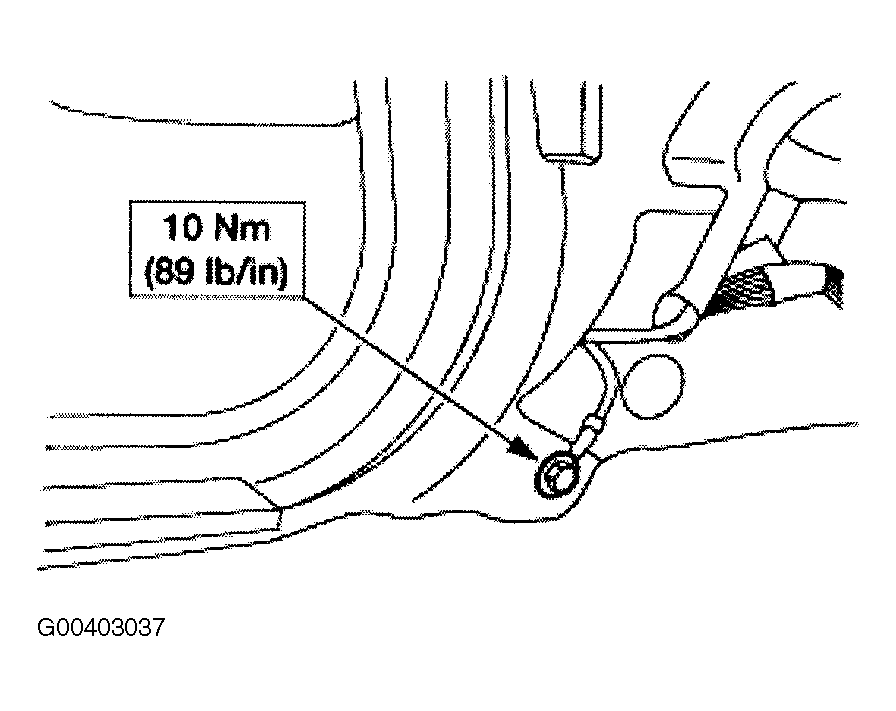
  8. Install the LH ground bolt.
    Fig 7: Installing LH Ground Bolt
    G00403037Courtesy of FORD MOTOR CO.
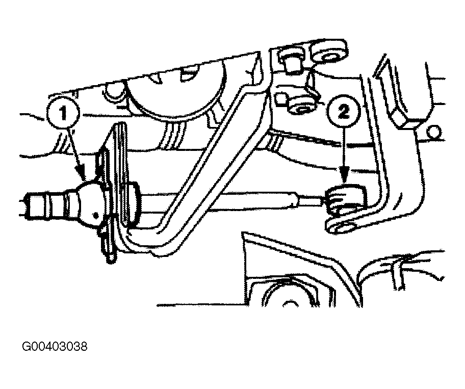
  9. If equipped, connect the transmission shift cable to the steering column.
    1. Connect the cable to the steering column bracket.
    2. Connect the cable to the steering column shift tube lever.
    Fig 8: Installing Transmission Shift Cable To Steering Column
    G00403038Courtesy of FORD MOTOR CO.
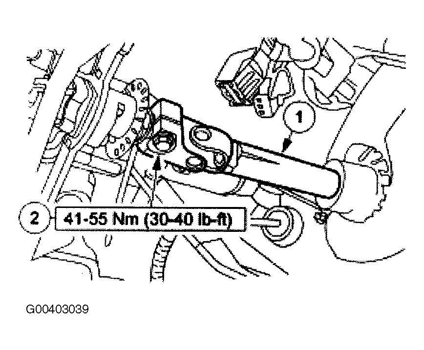
  10. Connect the intermediate shaft to the steering column shaft.
    1. Connect the intermediate shaft to the steering column shaft.
    2. Install a new pinch bolt.
    Fig 9: Installing Intermediate Shaft & Pinch Bolt
    G00403039Courtesy of FORD MOTOR CO.
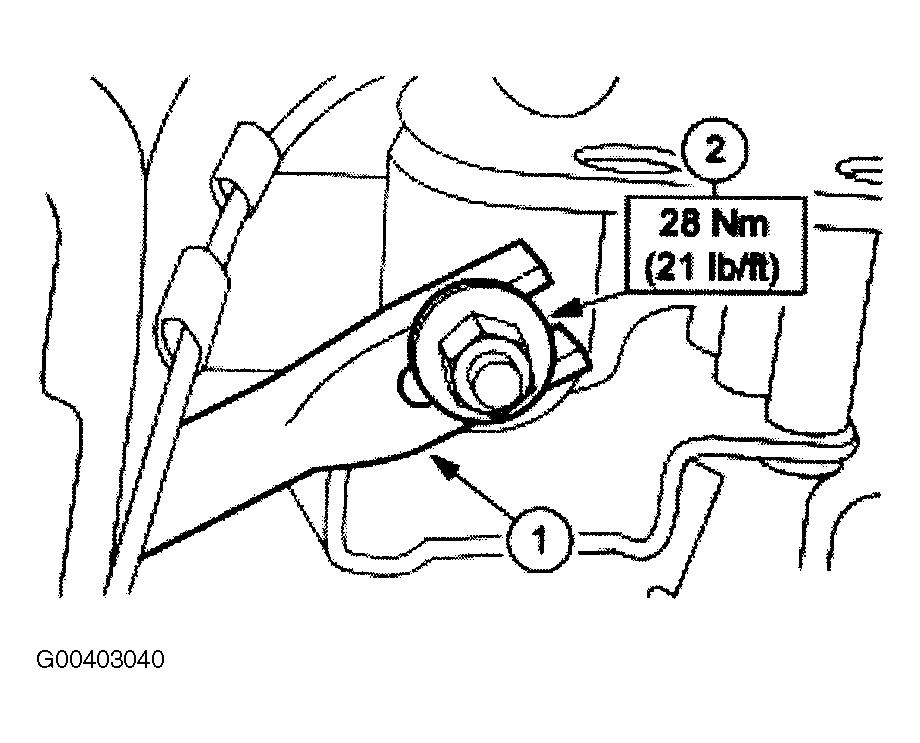
  11. Install the steering column brace.
    1. Position the steering column brace.
    2. Install the nut.
    Fig 10: Installing Steering Column Brace
    G00403040Courtesy of FORD MOTOR CO.
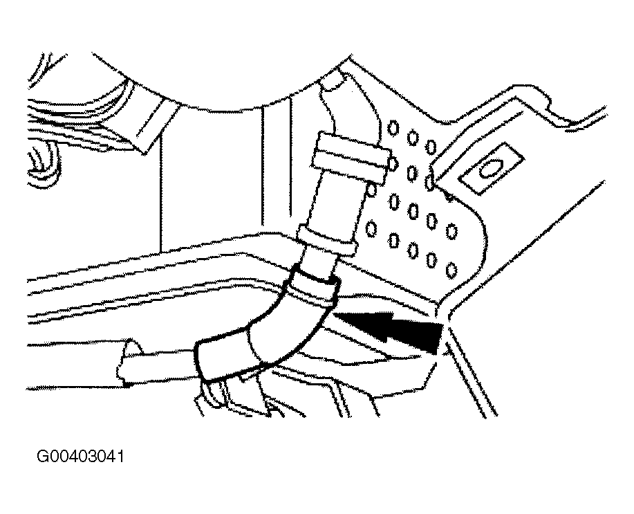
  12. Connect the vacuum connector.
    Fig 11: Installing Vacuum Connector
    G00403041Courtesy of FORD MOTOR CO.
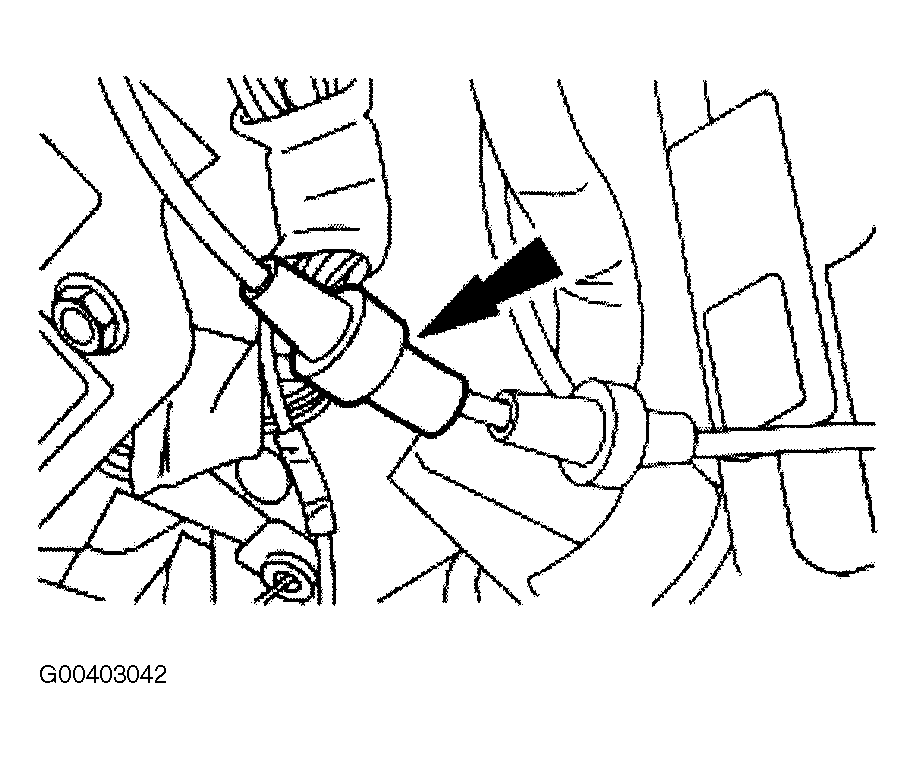
  13. Connect the parking brake release vacuum connector.
    Fig 12: Installing Parking Brake Release Vacuum Connector
    G00403042Courtesy of FORD MOTOR CO.
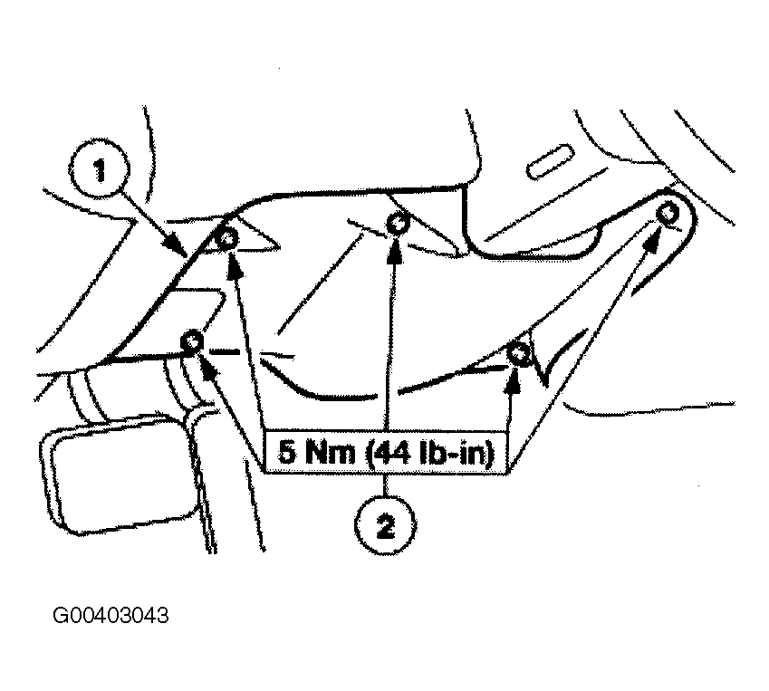
  14. Install the instrument panel steering column opening cover reinforcement.
    1. Position the instrument panel steering column opening cover reinforcement.
    2. Install the bolts.
    Fig 13: Installing Instrument Panel Steering Column Opening Cover Reinforcement
    G00403043Courtesy of FORD MOTOR CO.
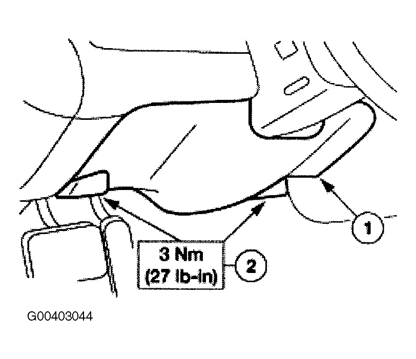
  15. Install the instrument panel lower steering column cover.
    1. Position the instrument panel lower steering column cover.
    2. Install the screws.
    Fig 14: Installing Instrument Panel Lower Steering Column Cover
    G00403044Courtesy of FORD MOTOR CO.
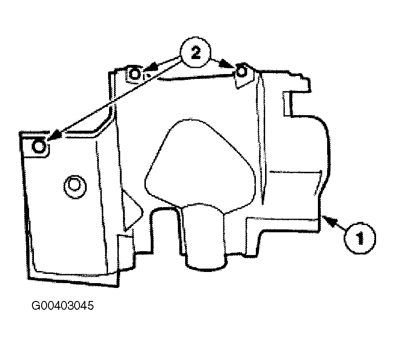
  16. Install the LH instrument panel insulator.
    1. Position the LH instrument panel insulator.
    2. Install the pin-type retainers.
      • Connect the courtesy lamp.
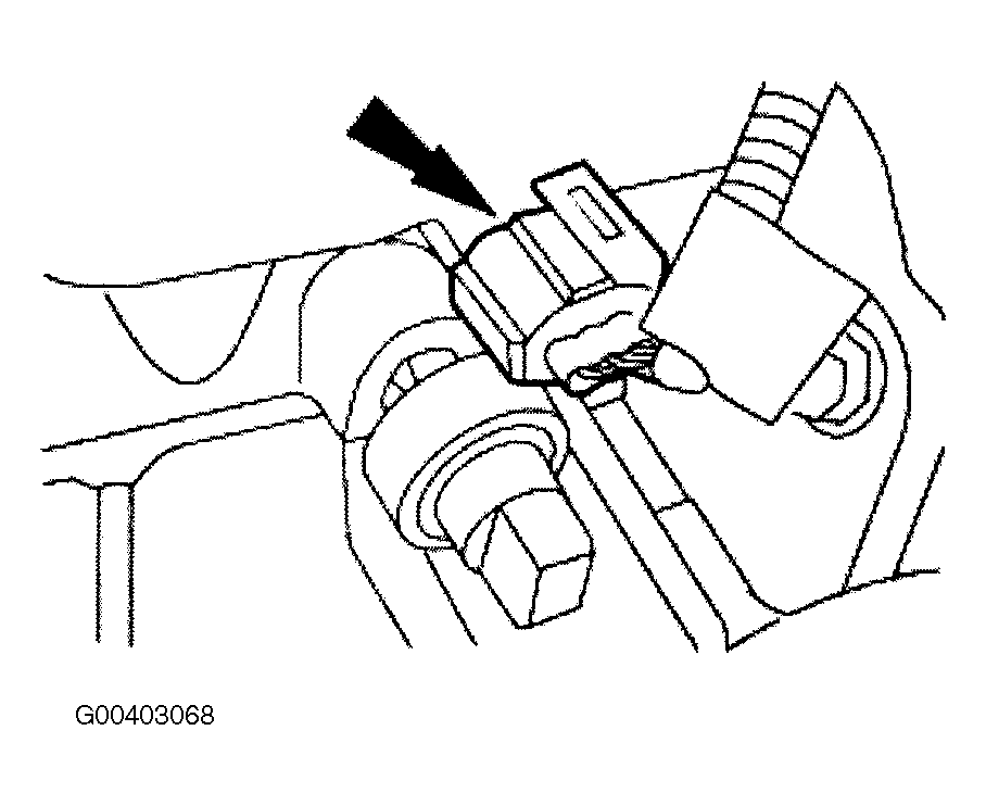
    Fig 15: Installing LH Instrument Panel Insulator
    G00403045Courtesy of FORD MOTOR CO.
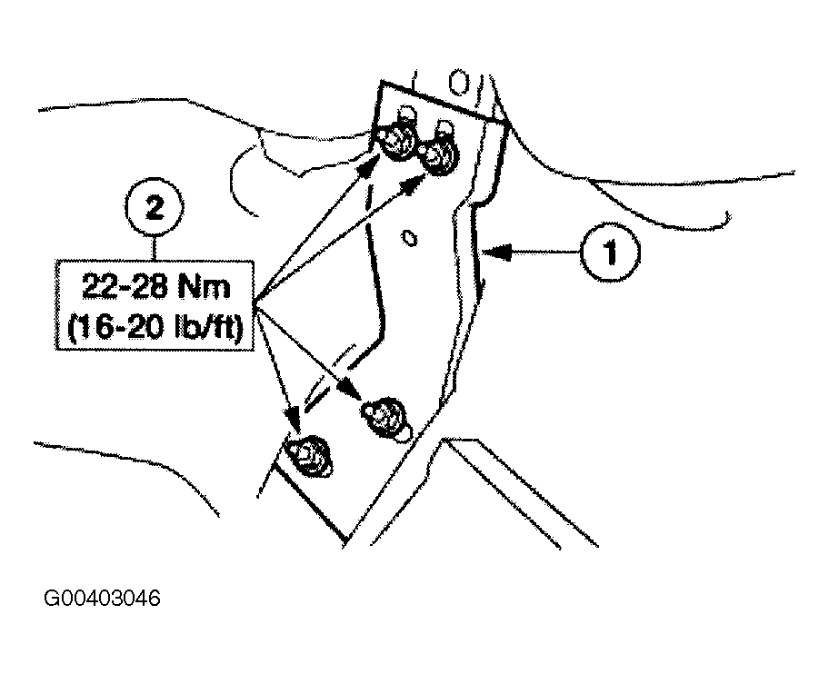
  17. Install the instrument panel tunnel brace.
    1. Position the instrument panel tunnel brace.
    2. Install the nuts.
    Fig 16: Installing Instrument Panel Tunnel Brace
    G00403046Courtesy of FORD MOTOR CO.
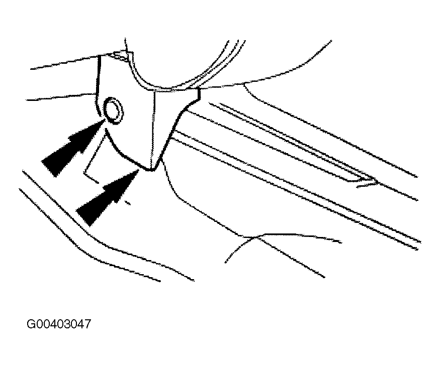
  18. Position the instrument panel tunnel brace cover and install the pin-type retainer.
    Fig 17: Installing Instrument Panel Tunnel Brace Cover & Pin-Type Retainer
    G00403047Courtesy of FORD MOTOR CO.
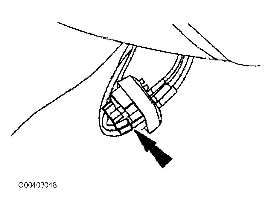
  19. Connect the climate control head vacuum harness connector.
    Fig 18: Installing Climate Control Head Vacuum Harness Connector
    G00403048Courtesy of FORD MOTOR CO.
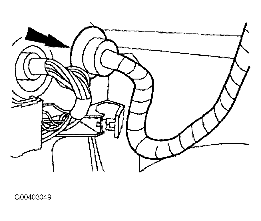
  20. Feed the RH wiring harness through the dash panel and seat the wiring grommet.
    Fig 19: Installing RH Wiring Harness
    G00403049Courtesy of FORD MOTOR CO.
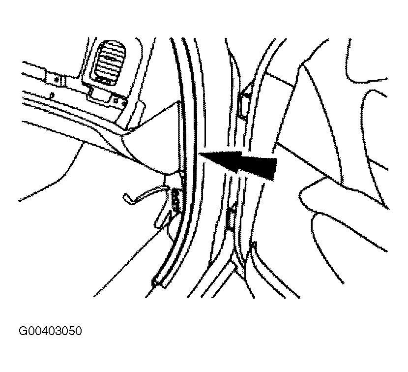
  21. Install the LH and RH door weatherstrip seals.
    Fig 20: Installing Door Weatherstrip Seals
    G00403050Courtesy of FORD MOTOR CO.
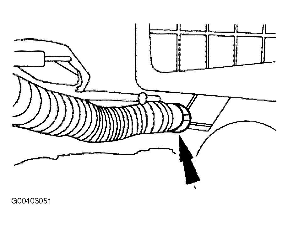
  22. If equipped, connect the EATC hose to the evaporator housing.
    Fig 21: Installing EATC Hose
    G00403051Courtesy of FORD MOTOR CO.
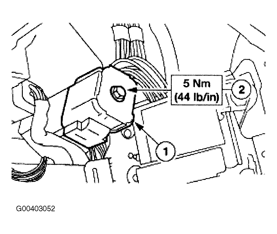
  23. Connect the RH bulkhead electrical connector.
    1. Connect the RH bulkhead electrical connector.
    2. Tighten the bolt.
    Fig 22: Installing RH Bulkhead Electrical Connector
    G00403052Courtesy of FORD MOTOR CO.
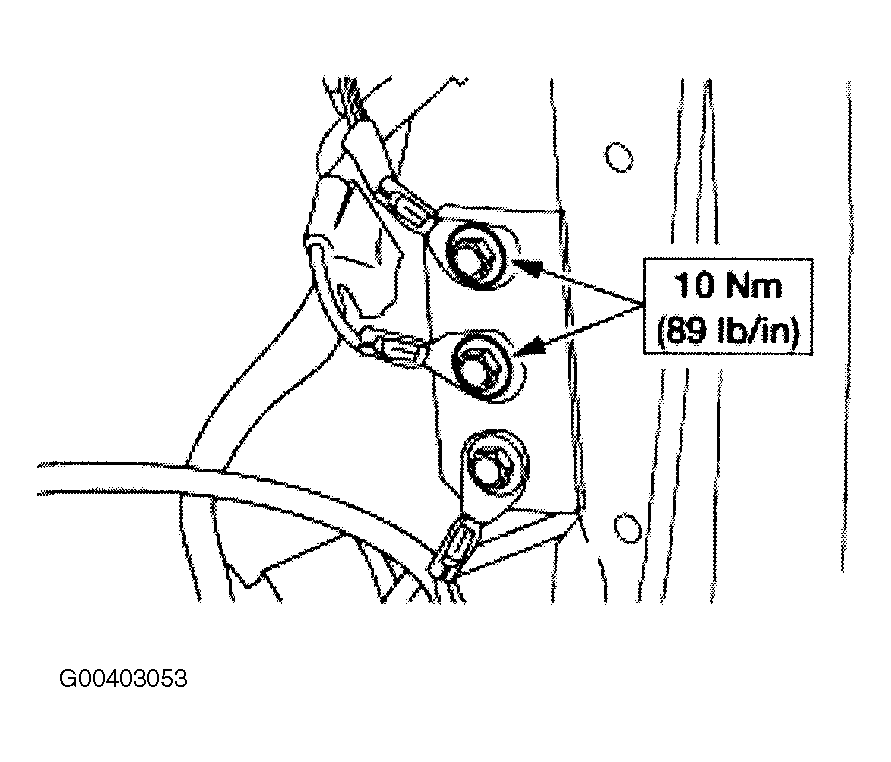
  24. Install the RH ground bolts.
    Fig 23: Installing RH Ground Bolts
    G00403053Courtesy of FORD MOTOR CO.
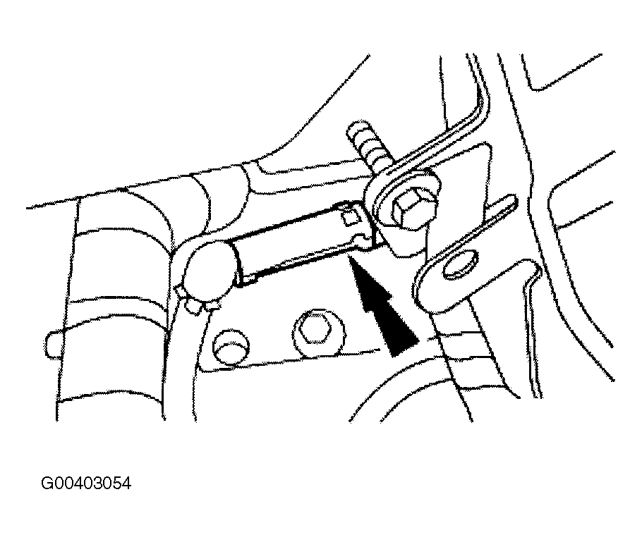
  25. Connect the antenna cable in-line connector.
    Fig 24: Installing Antenna Cable In-Line Connector
    G00403054Courtesy of FORD MOTOR CO.
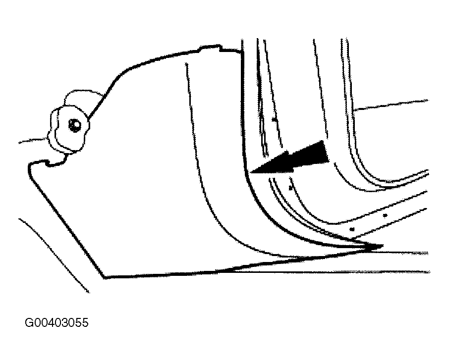
  26. Install the LH and RH A-pillar lower trim panels.
    Fig 25: Installing A-Pillar Lower Trim Panels
    G00403055Courtesy of FORD MOTOR CO.
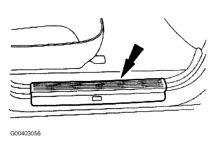
  27. Install the RH instrument panel lower insulator.
    1. Position the RH instrument panel lower insulator.
    2. Engage the locking tab.
    3. Install the pin-type retainers.
      • Connect the courtesy lamp.
    Fig 26: Installing Instrument Panel Lower Insulator
    G00403056Courtesy of FORD MOTOR CO.
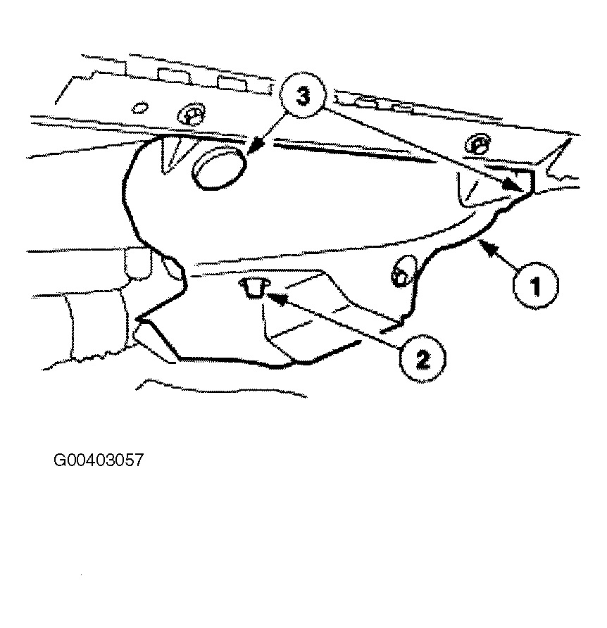
  28. Install the RH instrument panel lower insulator.
    1. Position the RH instrument panel lower insulator.
    2. Engage the locking tab.
    3. Install the pin-type retainers.
      • Connect the courtesy lamp.
    Fig 27: Installing RH Instrument Panel Lower Insulator
    G00403057Courtesy of FORD MOTOR CO.
  29. Remove the RH front wheel and tire assembly.
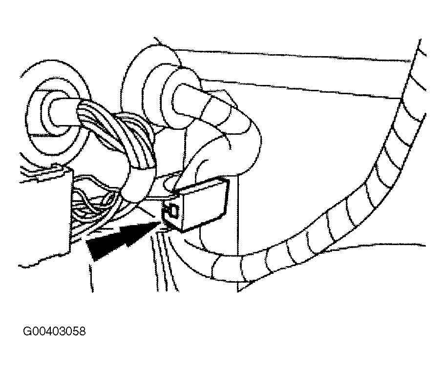
  30. Lock the RH wiring harness into the guide.
    Fig 28: Identifying RH Wiring Harness Guide
    G00403058Courtesy of FORD MOTOR CO.
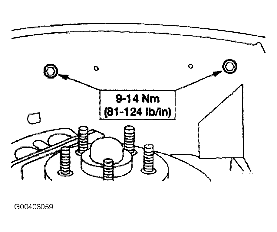
  31. Install the upper fender splash shield.
    • Install the bolts.
    Fig 29: Installing Upper Fender Splash Shield
    G00403059Courtesy of FORD MOTOR CO.
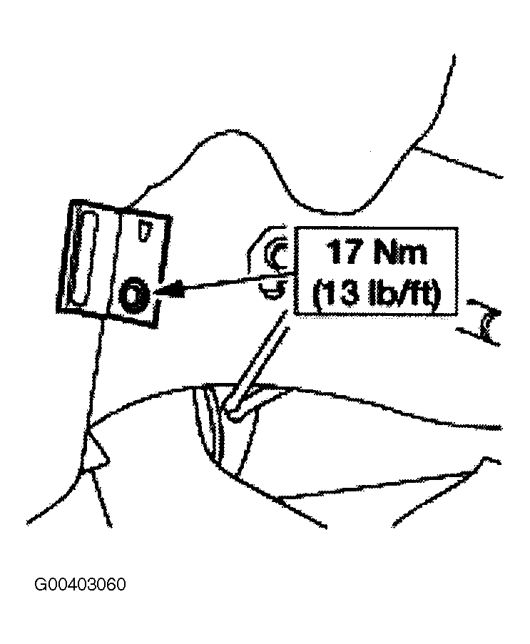
  32. Install the lower fender splash shield locator and bolt.
    Fig 30: Installing Lower Fender Splash Shield Locator & Bolt
    G00403060Courtesy of FORD MOTOR CO.
  33. Install the RH front wheel and tire assembly.
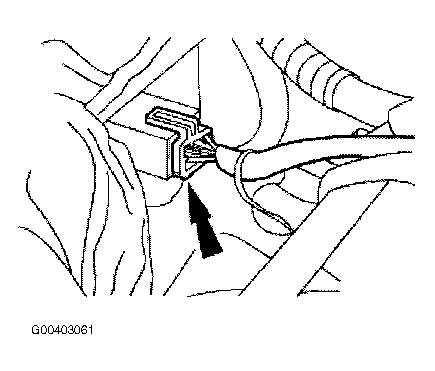
  34. Connect the blower motor controller electrical connector.
    • Engage the wiring harness locators.
    Fig 31: Installing Blower Motor Controller Electrical Connector
    G00403061Courtesy of FORD MOTOR CO.
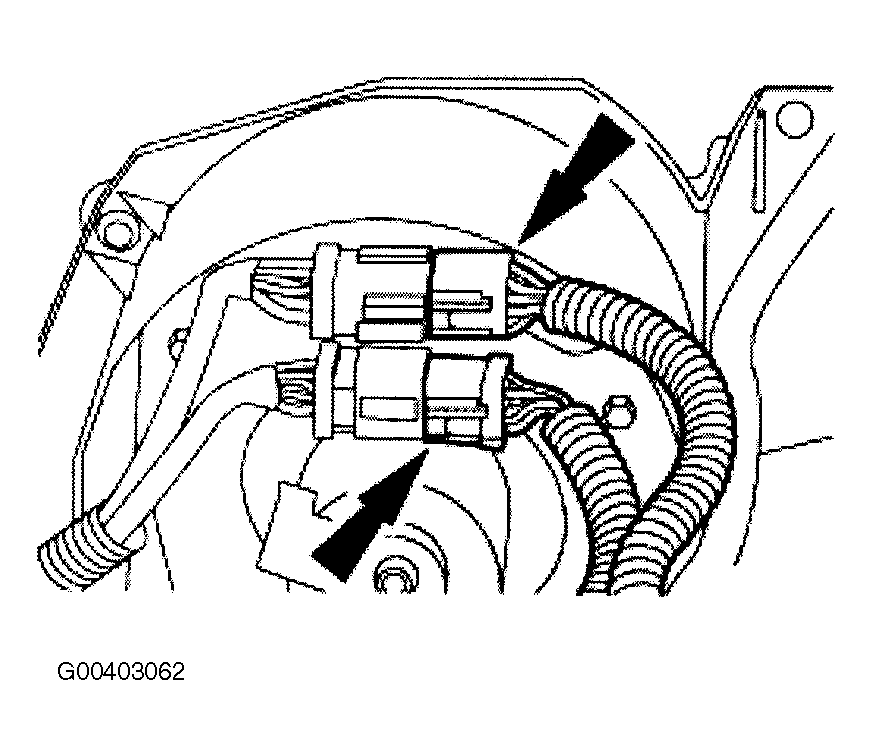
  35. Connect the RH engine compartment in-line wiring harness connectors.
    Fig 32: Installing RH Engine Compartment In-Line Wiring Harness Connectors
    G00403062Courtesy of FORD MOTOR CO.
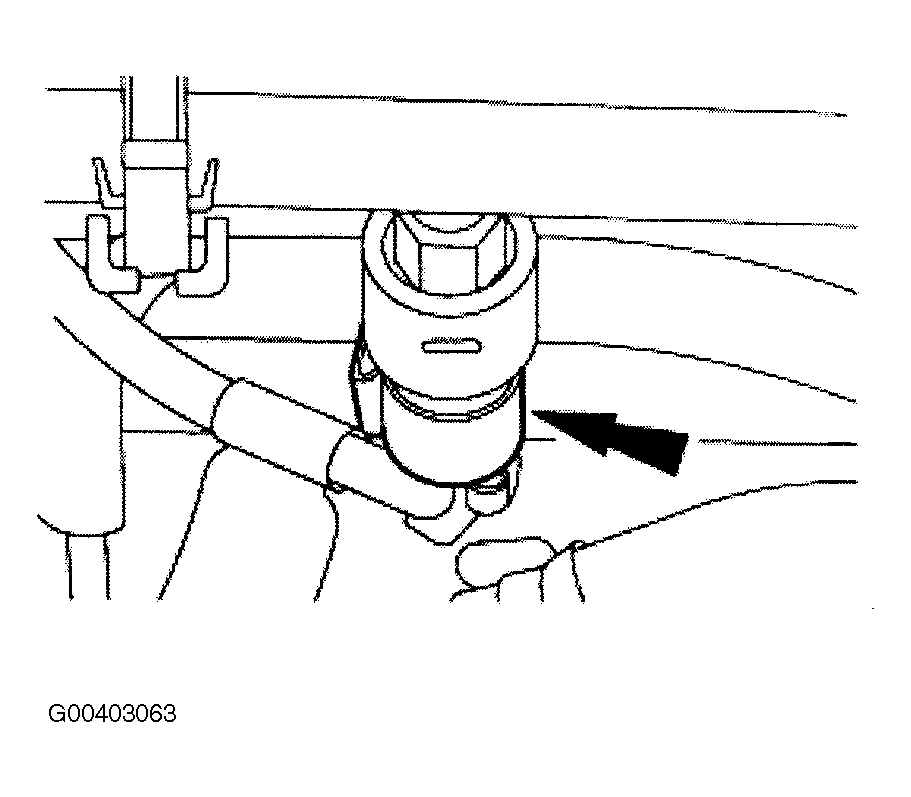
  36. Connect the A/C pressure cut-off switch electrical connector.
    Fig 33: Installing A/C Pressure Cut-Off Switch Electrical Connector
    G00403063Courtesy of FORD MOTOR CO.
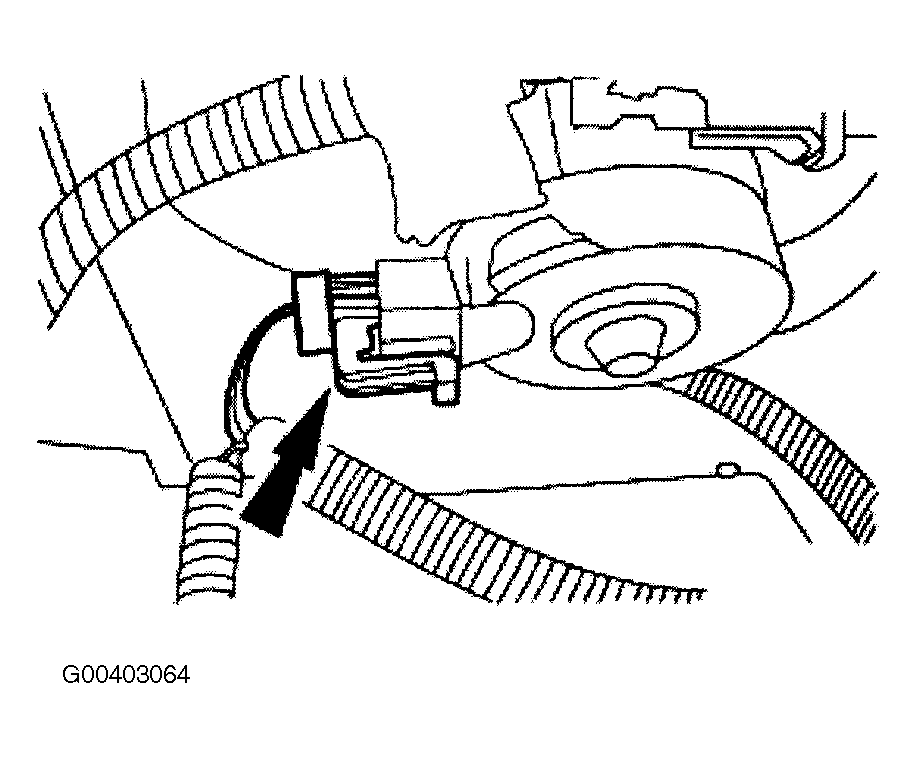
  37. Connect the blower motor electrical connector.
    Fig 34: Installing Blower Motor Electrical Connector
    G00403064Courtesy of FORD MOTOR CO.
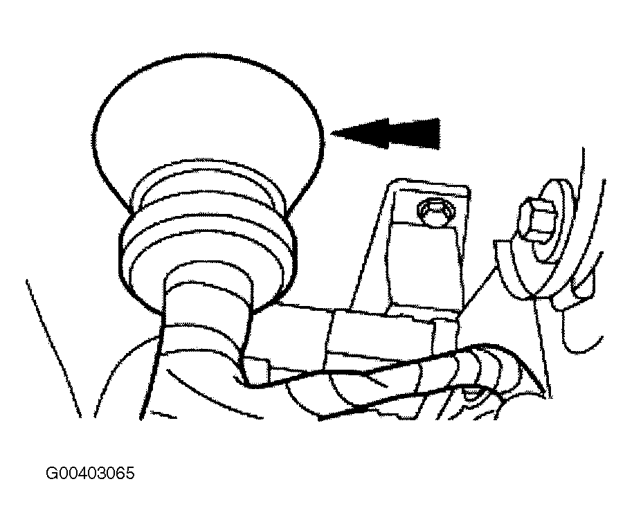
  38. Seat the LH wiring harness grommet.
    Fig 35: Installing LH Wiring Harness Grommet
    G00403065Courtesy of FORD MOTOR CO.
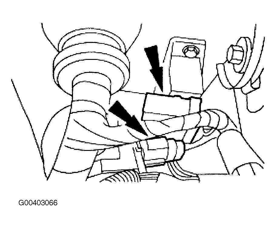
  39. Connect the LH engine compartment in-line electrical connectors.
    Fig 36: Installing LH Engine Compartment In-Line Electrical Connectors
    G00403066Courtesy of FORD MOTOR CO.
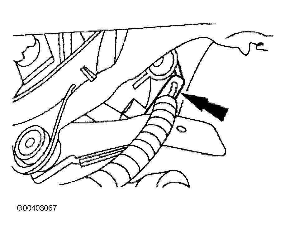
  40. Connect the windshield wiper motor electrical connector.
    • Engage the wiring harness locators.
    Fig 37: Installing Windshield Wiper Motor Electrical Connector
    G00403067Courtesy of FORD MOTOR CO.
  41. Connect the brake fluid sensor electrical connector.
    Fig 38: Installing Brake Fluid Sensor Electrical Connector
    G00403068Courtesy of FORD MOTOR CO.
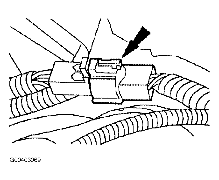
  42. Connect the LH engine compartment in-line electrical connector.
    • Engage the wiring harness locators.
    Fig 39: Installing Engine Compartment In-Line Electrical Connector
    G00403069Courtesy of FORD MOTOR CO.
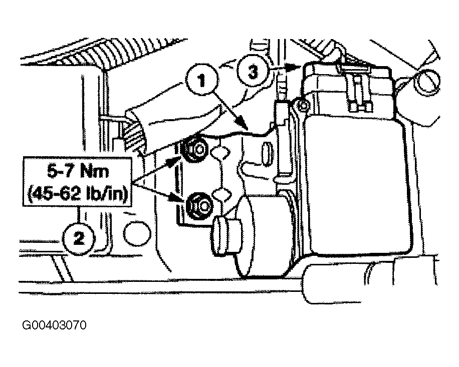
  43. Install the speed control servo.
    1. Position the speed control servo.
    2. Install the nuts.
    3. Connect the electrical connector.
    Fig 40: Installing Speed Control Servo
    G00403070Courtesy of FORD MOTOR CO.
  44. If equipped, install the floor console. For additional information, refer to FLOOR CONSOLE .
  45. Repower the Supplemental Restraint System (SRS). For additional information, refer to DISABLING & ACTIVATING AIR BAG SYSTEM .