LEMON Manuals: Even more car manuals for everyone: 1960-2025
Home >> Ford >> 2002 >> Crown Victoria Base, 4.6 9 >> Repair and Diagnosis >> Transmission >> Automatic Trans >> Automatic Transmission >> In-Vehicle Repair >> Manual Control Lever Shaft & Seal >> Installation

Manual Control Lever Shaft & Seal: Installation

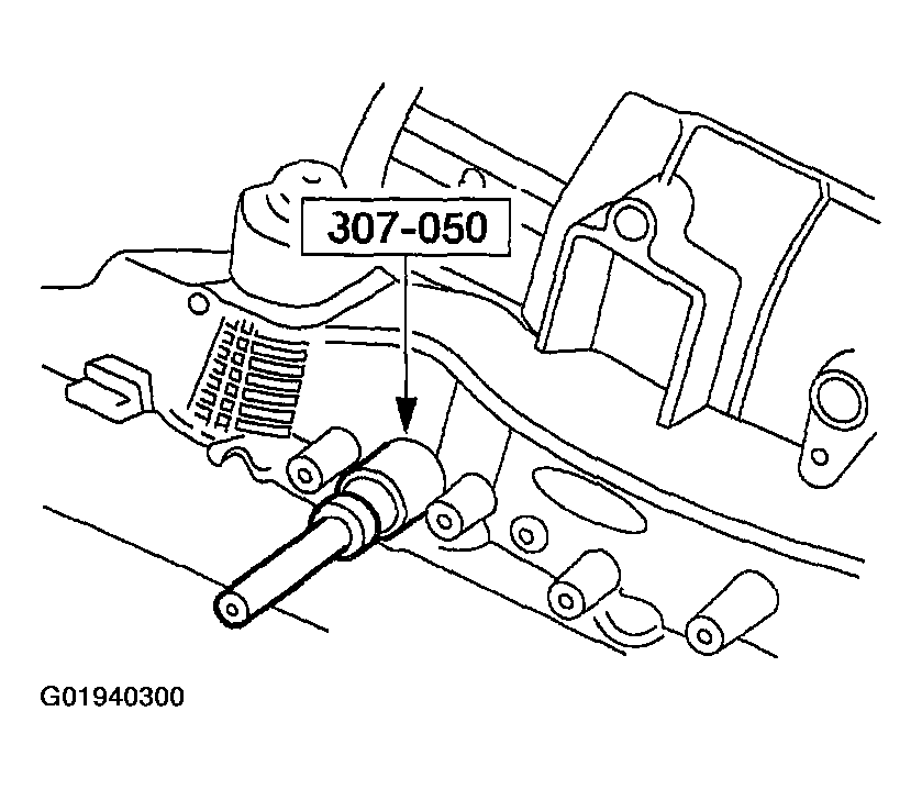
  1. Using the special tool, install the manual control lever shaft seal.
    Fig 1: Identifying Shift Shaft Fluid Seal Installer
    G01940300Courtesy of FORD MOTOR CO.
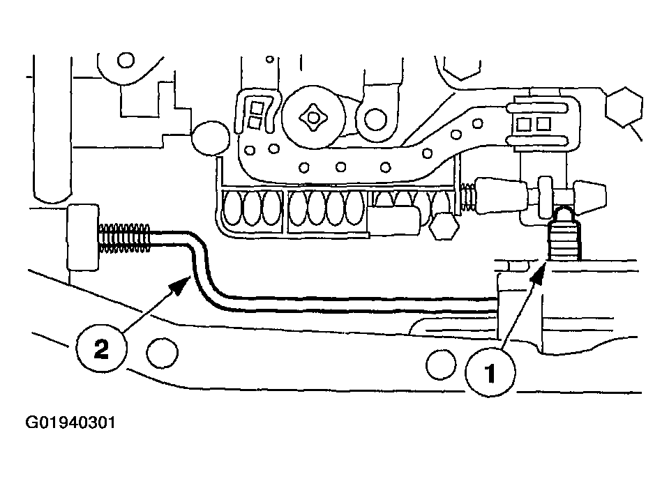
  2. Install the parking lever actuating rod.
    1. Install the manual valve detent lever.
    2. Install the parking lever actuating rod.
    Fig 2: Identifying Manual Valve Detent Lever & Parking Lever Actuating Rod
    G01940301Courtesy of FORD MOTOR CO.
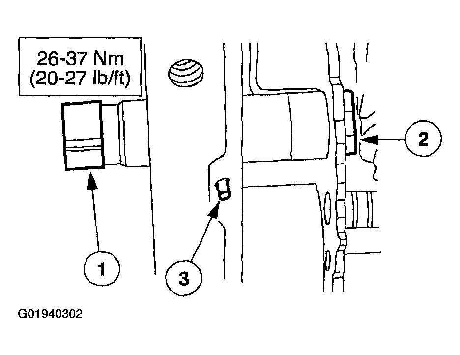
  3. Install the manual control lever shaft.
    1. Install the manual control lever shaft.
    2. Install the nut.
    3. Install the manual control lever shaft retaining pin.
    Fig 3: Identifying Manual Control Lever Shaft, Nut & Manual Control Lever Shaft Retaining Pin
    G01940302Courtesy of FORD MOTOR CO.
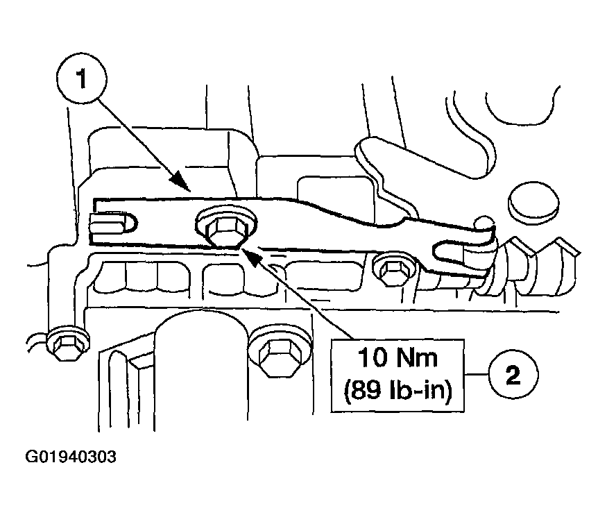
  4. Install the manual valve detent lever spring.
    1. Position the manual valve detent lever spring.
    2. Install the bolt.
    Fig 4: Tightening Manual Valve Detent Lever Spring Bolt
    G01940303Courtesy of FORD MOTOR CO.
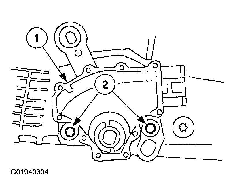
  5. Install the digital TR sensor.
    1. Install the digital TR sensor.
    2. Loosely install the bolts.
    Fig 5: Identifying Digital TR Sensor & Bolts
    G01940304Courtesy of FORD MOTOR CO.
  6. NOTE: Manual shift lever shaft must be in the neutral position.
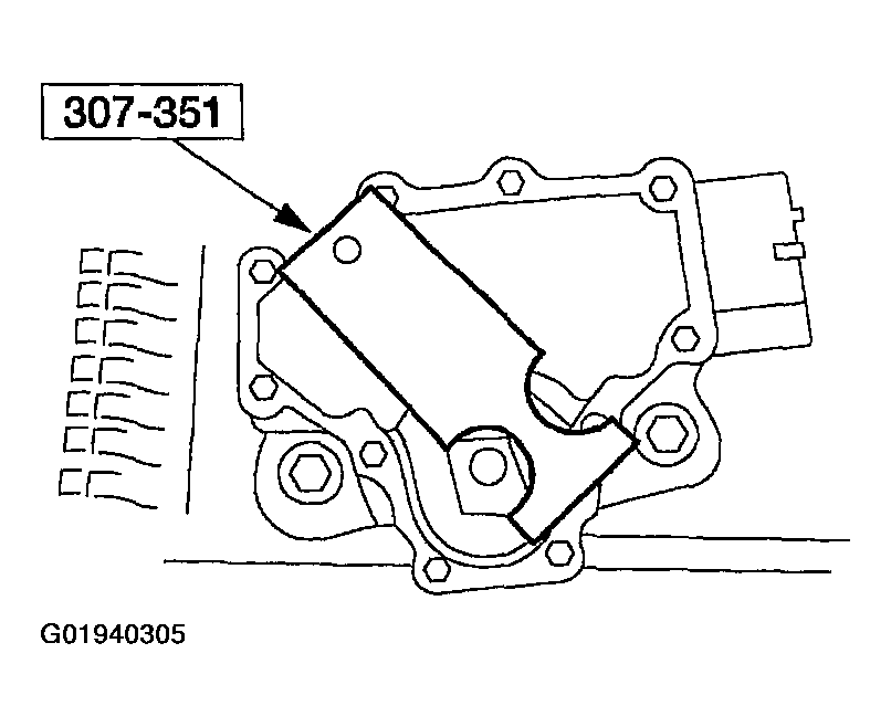
    Fig 6: Identifying TR Sensor Alignment Gauge
    G01940305Courtesy of FORD MOTOR CO.
  7. Using the special tool, align the digital TR sensor slots. The tool is designed to fit snugly.
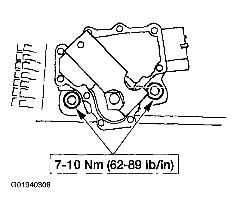
  8. Tighten the bolts.
    Fig 7: Tightening TR Sensor Bolts
    G01940306Courtesy of FORD MOTOR CO.
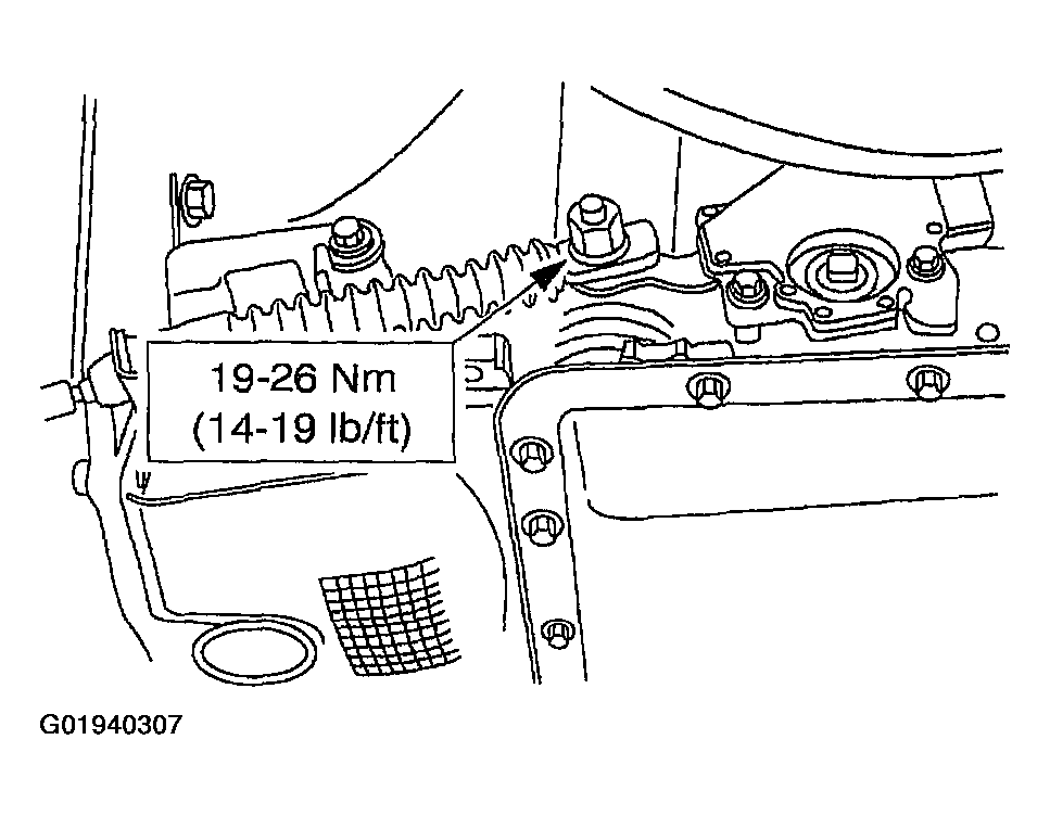
  9. With the manual lever in overdrive, connect the shift control cable.
    Fig 8: Tightening Shift Linkage Nut
    G01940307Courtesy of FORD MOTOR CO.
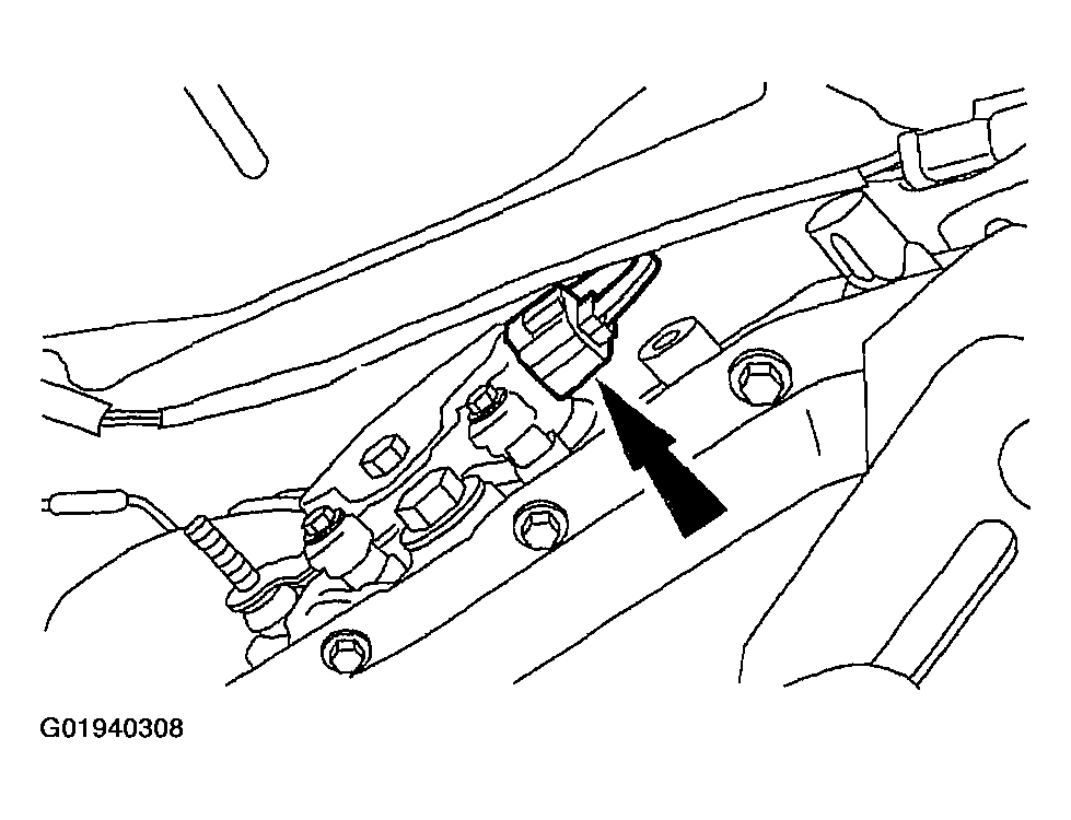
  10. Install the digital TR sensor electrical connector.
    Fig 9: Identifying Digital TR Sensor Electrical Connector
    G01940308Courtesy of FORD MOTOR CO.
  11. Install the filter and transmission fluid pan. For additional information, refer to FLUID PAN, GASKET & FILTER .