Automatic Transmission: Removal: Transmission: Removal
CAUTION:
Whenever a transmission has been disassembled to install new parts the transmission fluid cooler tubes must be cleaned and backflushed using a suitable torque converter/fluid cooler cleaner. A new oil-to-air (OTA) cooler must also be installed. When internal wear or damage has occurred in the transmission, metal particles, clutch plate material or band material may have been carried into the torque converter and fluid cooler. These contaminants are a major cause of recurring transmission troubles and must be removed from the system before the transmission is put back into service.
NOTE:
After transmission is removed for a major overhaul, it is important to completely clean all transmission components, including torque converter, oil-to-air cooler, cooler inlet tube, main control valve body, clutches and all coasting booster valve shuttle balls after any transmission service that generates contamination. These contaminants are a major cause for recurring transmission concerns and must be removed from the system before the transmission is returned to service.
The cleaning of foreign material from the direct clutch check ball is often omitted. This omission can lead to a repeat servicing of the transmission.
A new OTA cooler must be installed under the following conditions. For additional information, refer to AUXILIARY TRANSMISSION FLUID COOLER .
- Evidence of transmission assembly or fluid contamination is found due to the following transmission or converter failure modes:
- Major Metallic Failure
- Multiple Clutches Or Clutch Plate Failures
- Sufficient Component Wear Which Results In Metallic Contamination
- If equipped with air suspension, deactivate the system by turning the air suspension switch OFF.
- Install a memory saver.
- Disconnect the battery ground cable. For additional information, refer to BATTERY, MOUNTING & CABLES .
- Raise the vehicle on a hoist.
- Remove the radiator air deflector.
- Position a drain pan under the vehicle.
- Drain transmission fluid.
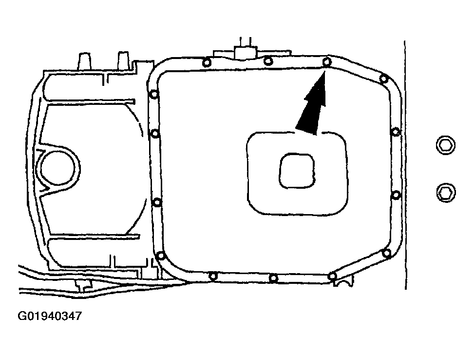
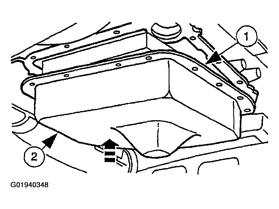
- Loosen the transmission fluid pan bolts and allow fluid to drain. After fluid is drained remove the bolts and the pan.
- Install the transmission fluid pan and the old gasket.
- Position the transmission fluid pan gasket.
- Position the transmission fluid pan.
- Remove the drain pan.
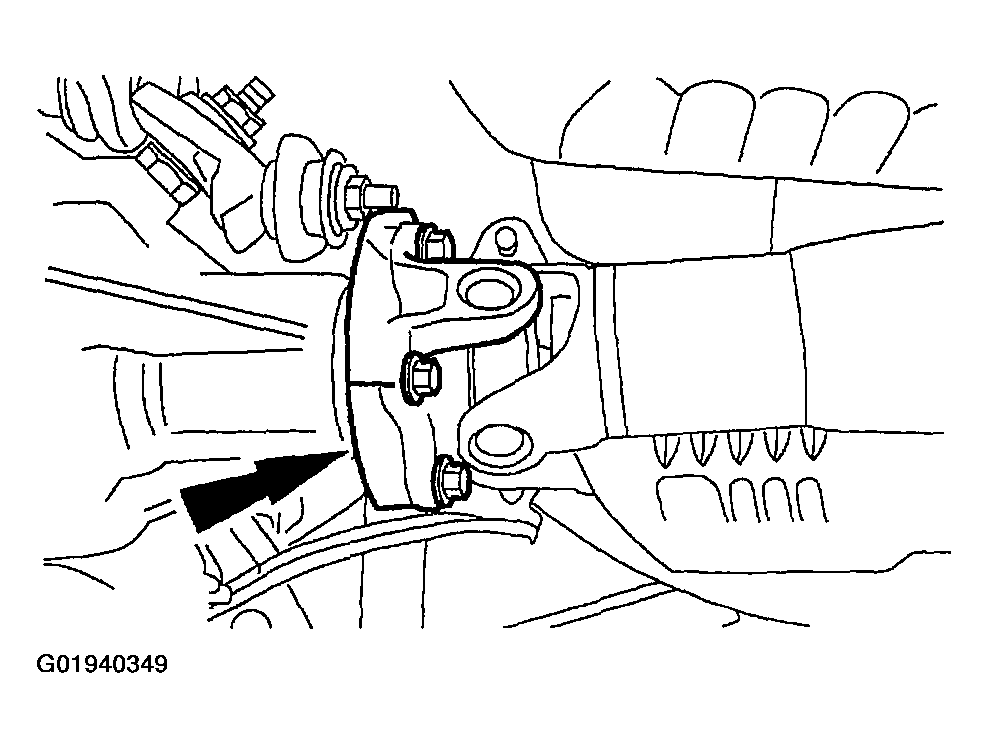
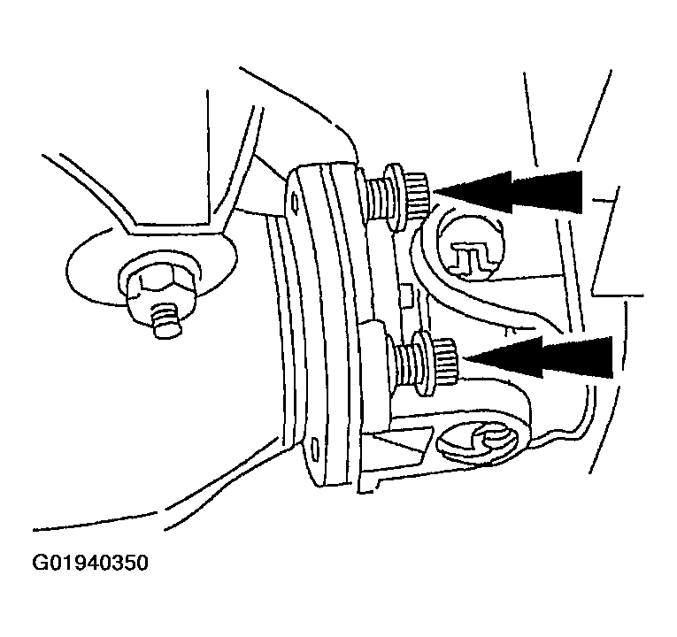
- Mark the rear driveshaft yoke and the axle pinion flange.
- Remove the four bolts.
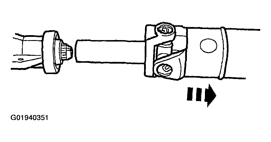
- Remove the driveshaft.
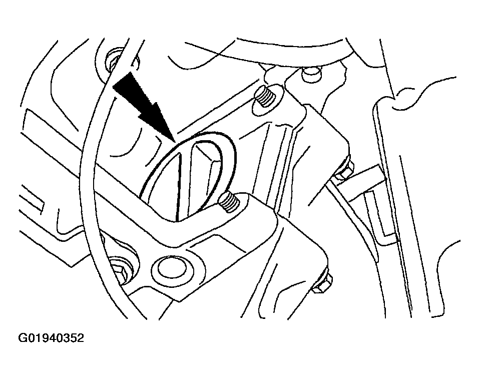
- Remove the torque converter access cover plug at the left rear engine block.
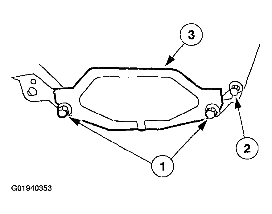
- Remove the torque converter access cover.
- Remove the bolts.
- Remove the bolt.
- Remove the inspection cover.
- Remove and discard the nuts.
- Disconnect the transmission shift linkage.
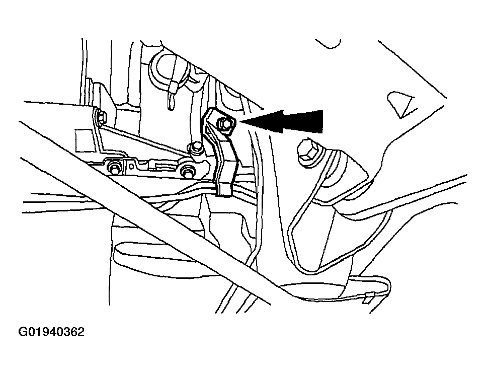
- Remove the shift cable bracket and position aside.
- Remove the three way catalytic converter. For additional information, refer to EXHAUST SYSTEM .
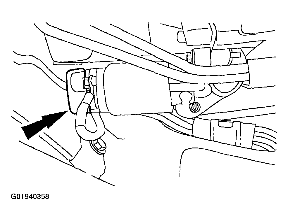
- Remove the ground strap.
- Remove the cap.
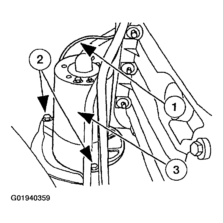
- Remove the starter.
- Disconnect the electrical connectors.
- Remove the bolts.
- Remove the starter.
- Disconnect the harness.
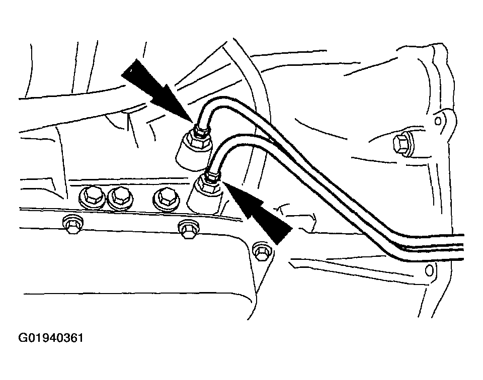
- Disconnect the transmission fluid cooler tubes.
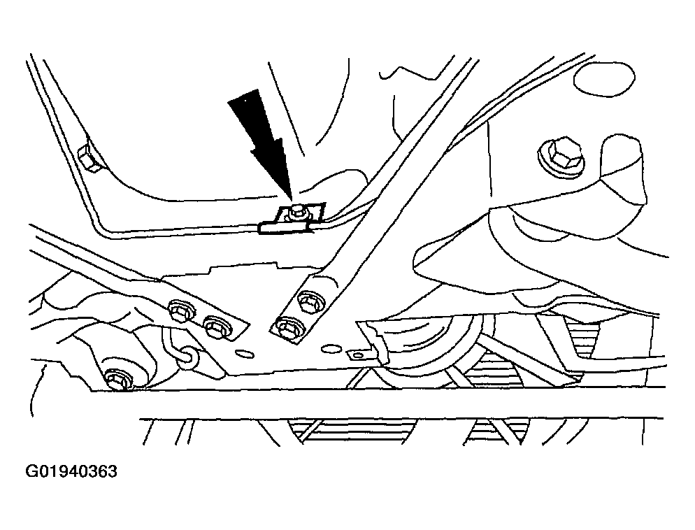
- Remove the cooler line bracket and position aside.
- Position the high-lift jack under the transmission.
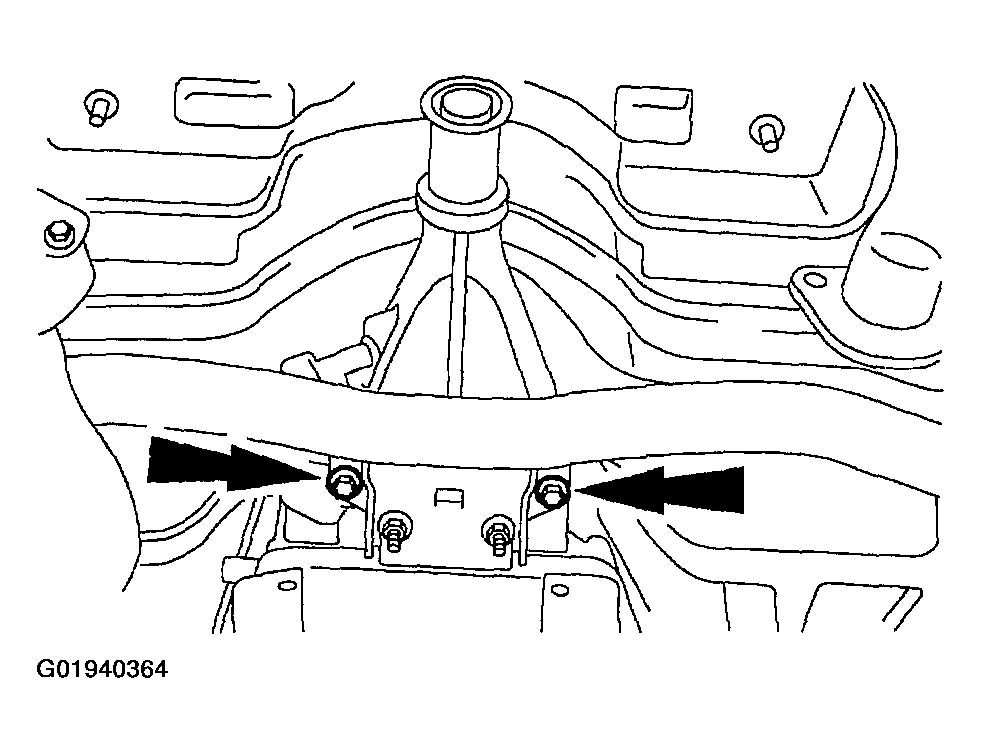
- Remove the bolt.
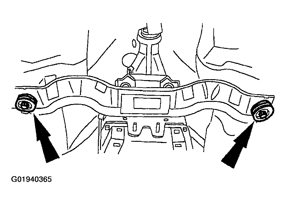
- Remove the bolts.
- Remove the transmission crossmember.
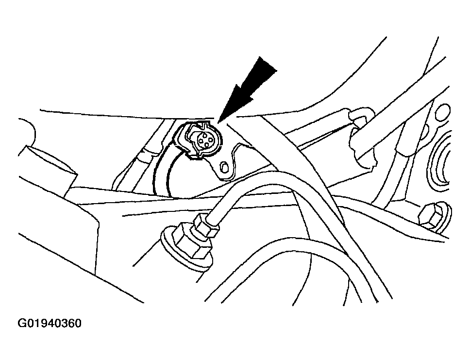
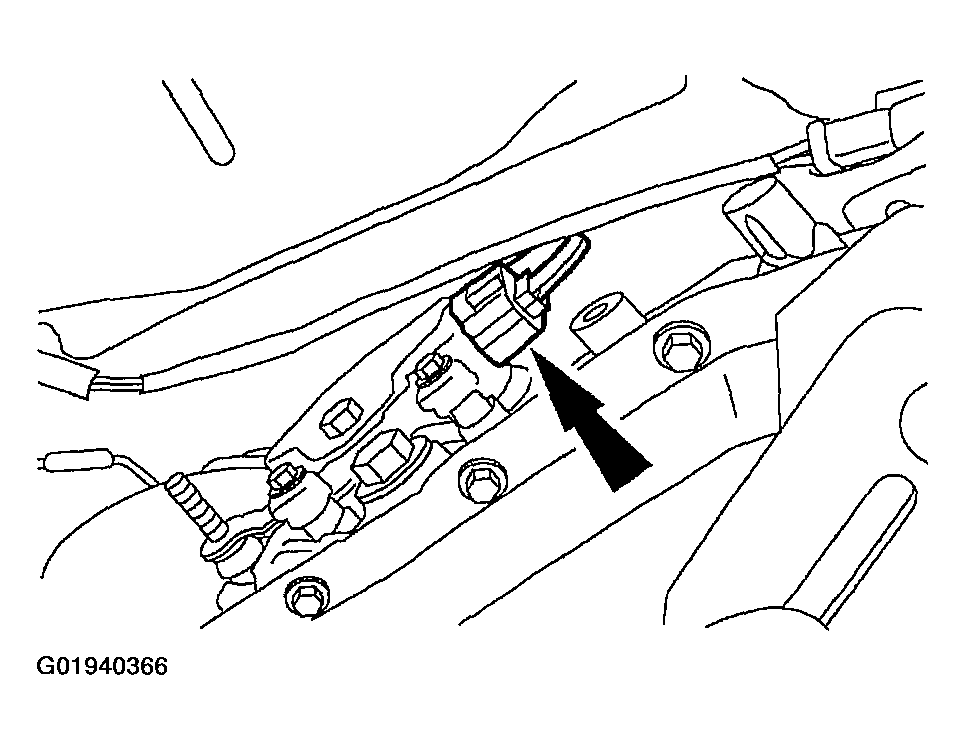
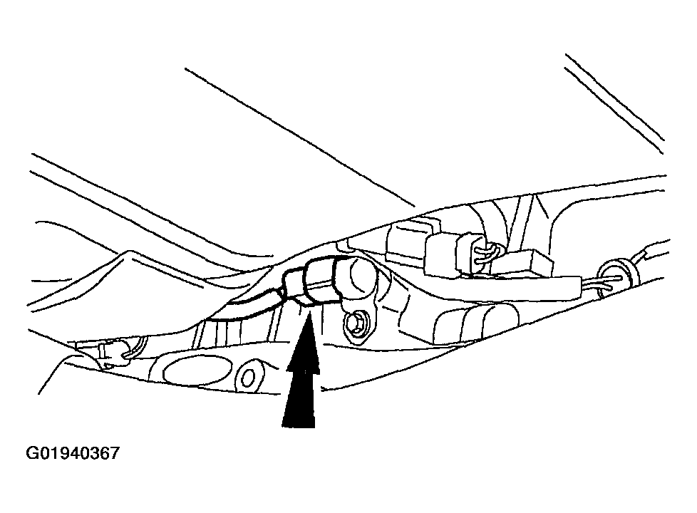
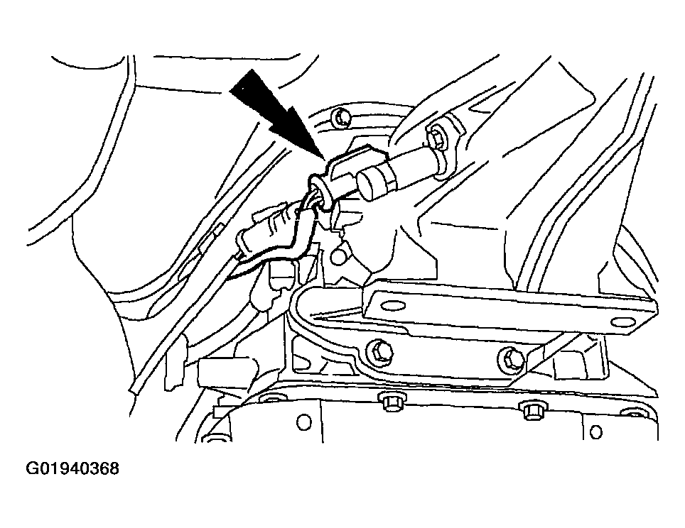
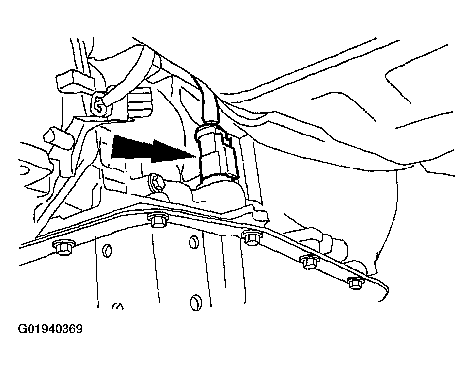
- Disconnect the digital transmission range (TR) sensor connector.
- Disconnect the output shaft speed (OSS) sensor connector.
- Disconnect the vehicle speed (VSS) sensor connector.
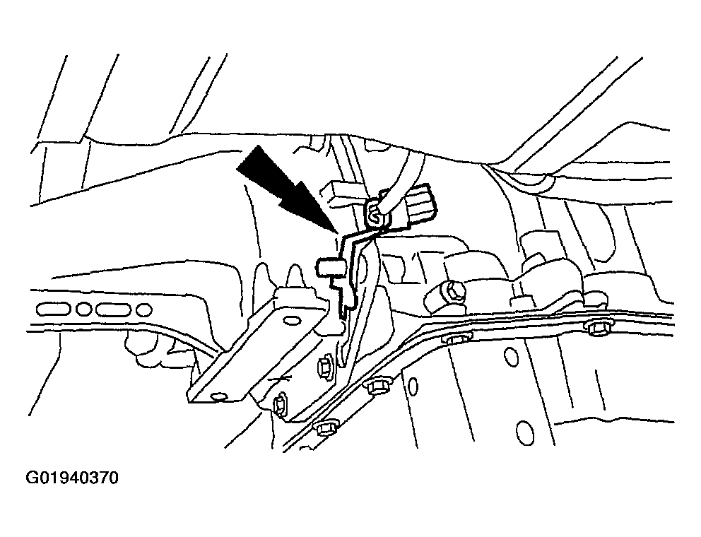
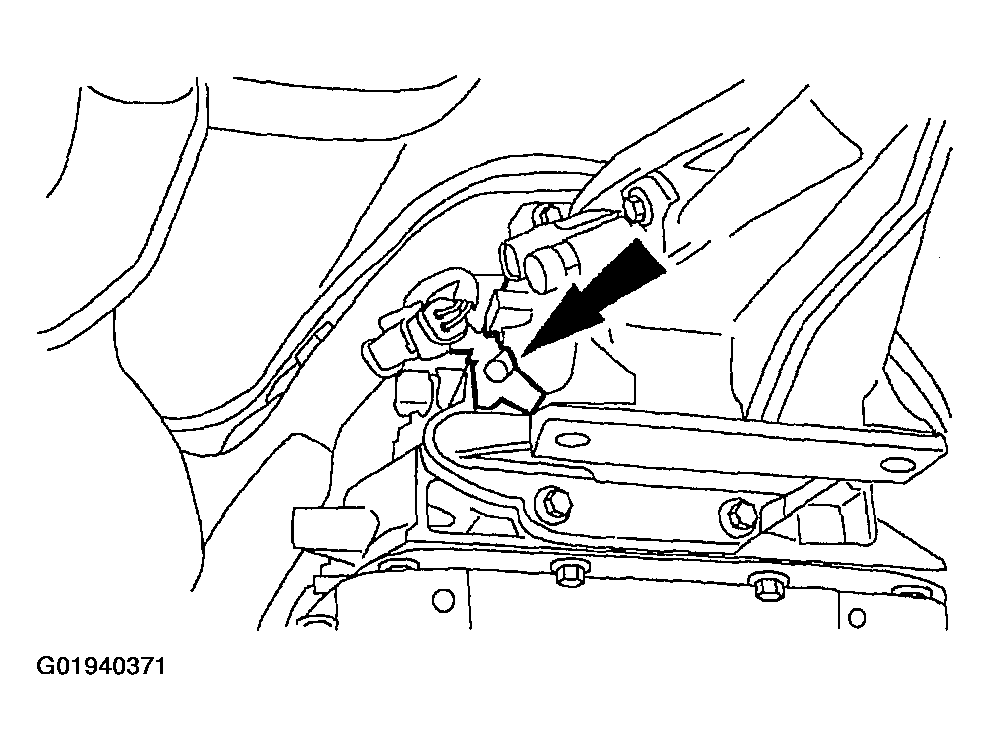
- Disconnect the transmission harness connector.
- Remove the HO2S connector from the stud.
- Remove the HO2S connector from the stud.
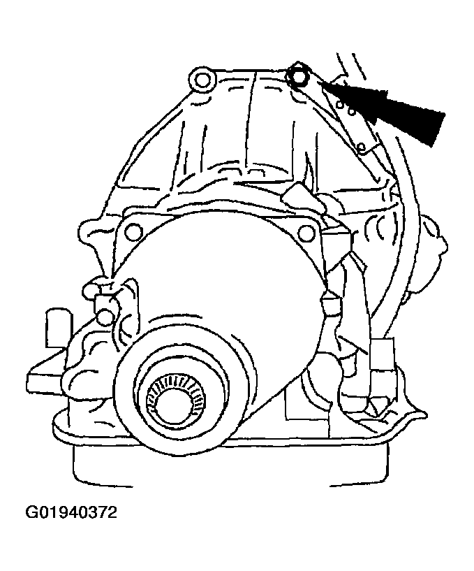
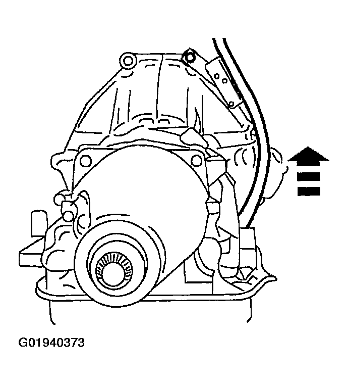
- Remove the bolt.
- Remove the fluid filler tube.
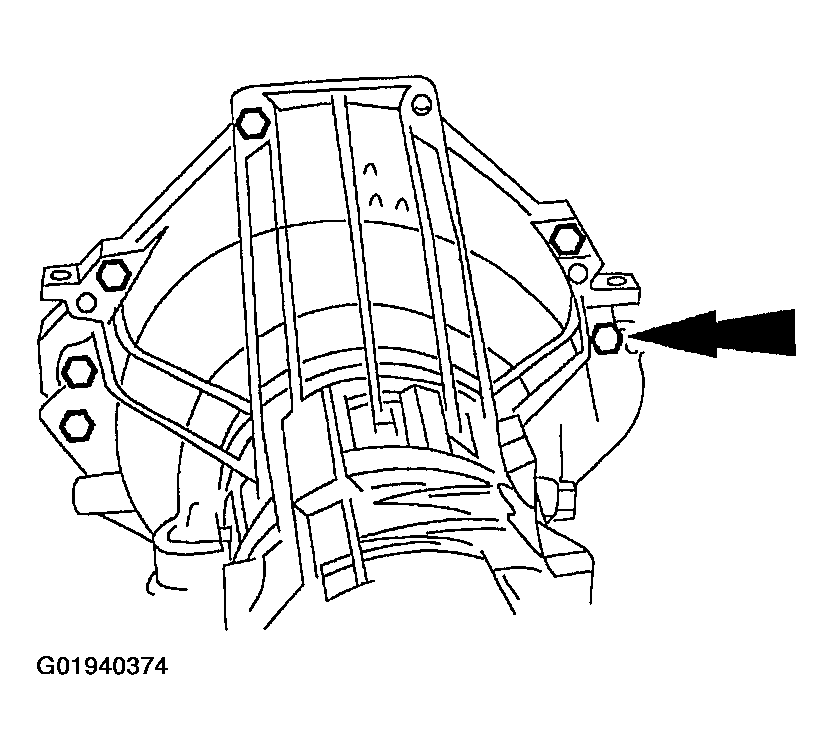
- Remove the bolts.
- Separate the transmission from the engine.
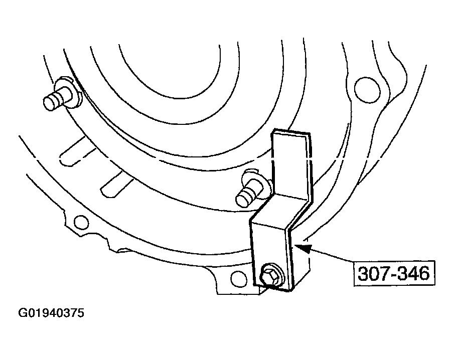
- Install the special tool and lower the transmission from the vehicle.
NOTE:
To maintain the initial driveshaft balance, mark the rear driveshaft yoke and the axle pinion flange so they may be installed in their original positions.
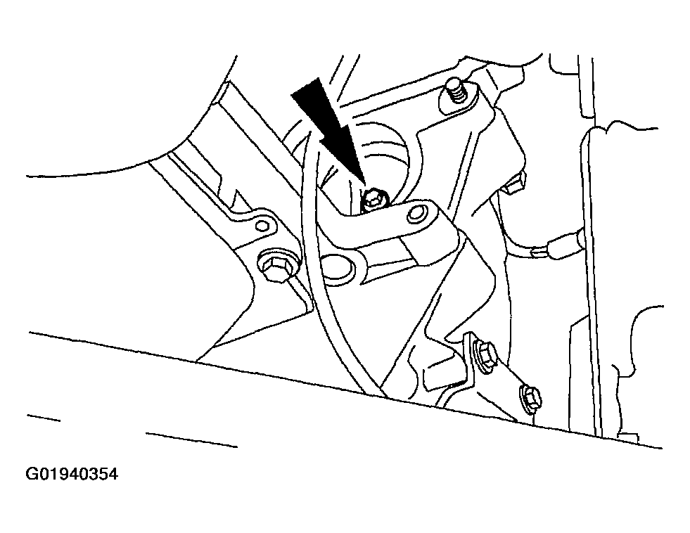
NOTE:
Make a reference mark on the shift cable linkage to the transmission.
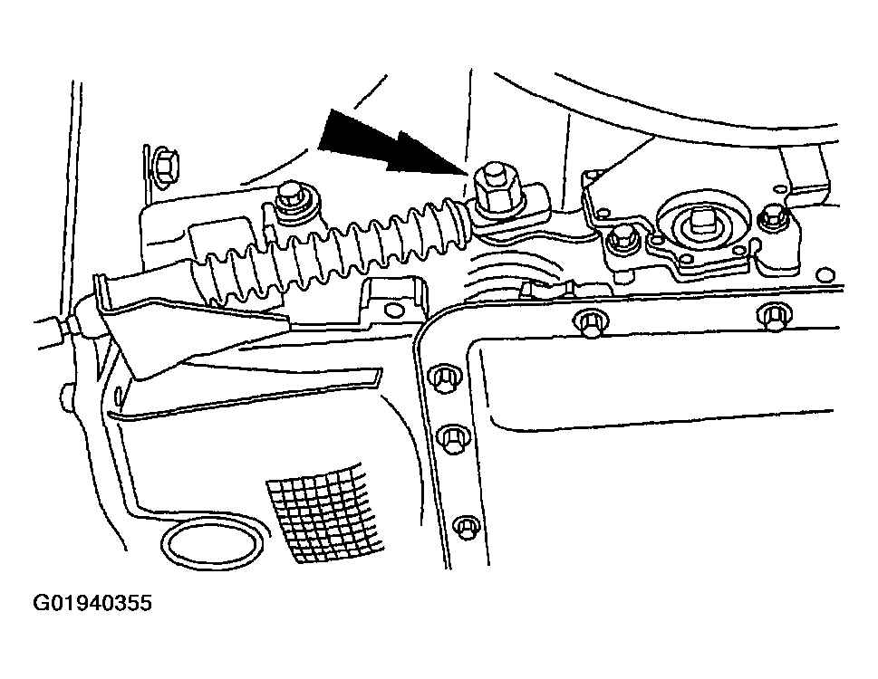
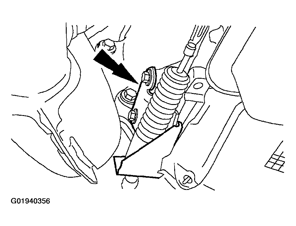
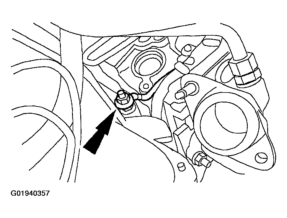
NOTE:
The case connectors must be held in place to prevent them from moving.
WARNING:
The torque converter is heavy. Personal injury may result if it falls out of the transmission. Secure the torque converter in the transmission. If the torque converter is dropped a new one must be installed.