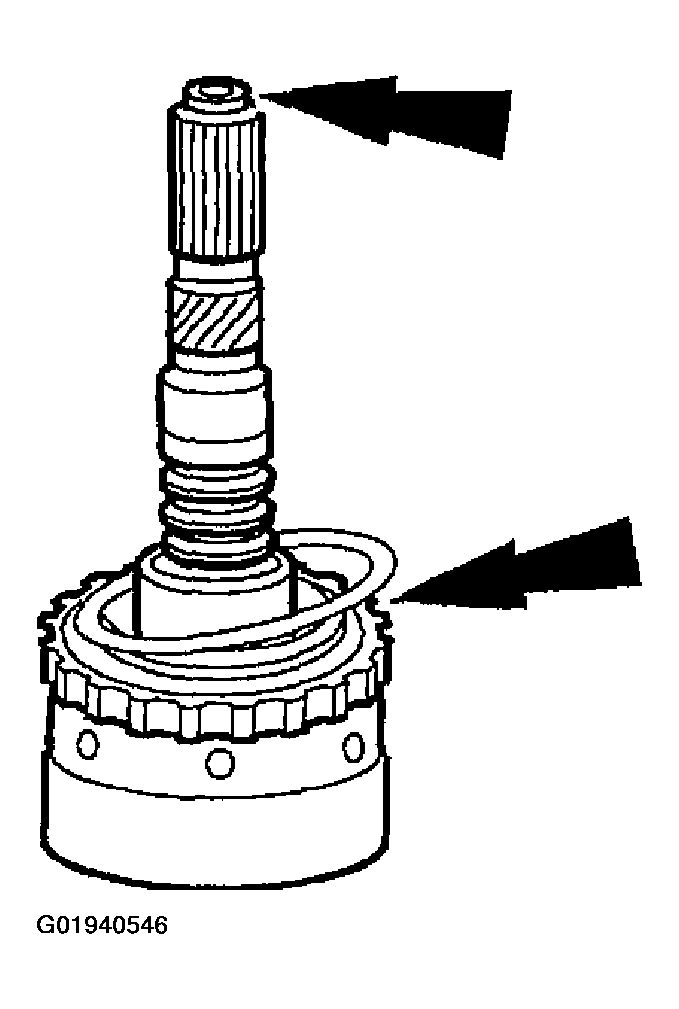
Output Shaft & Direct Clutch Cylinder: Assembly
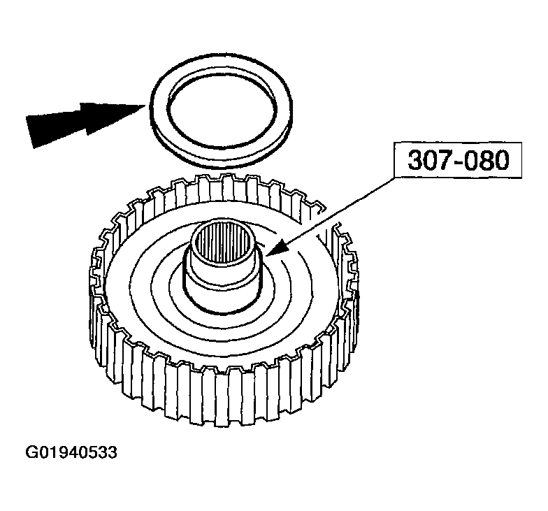
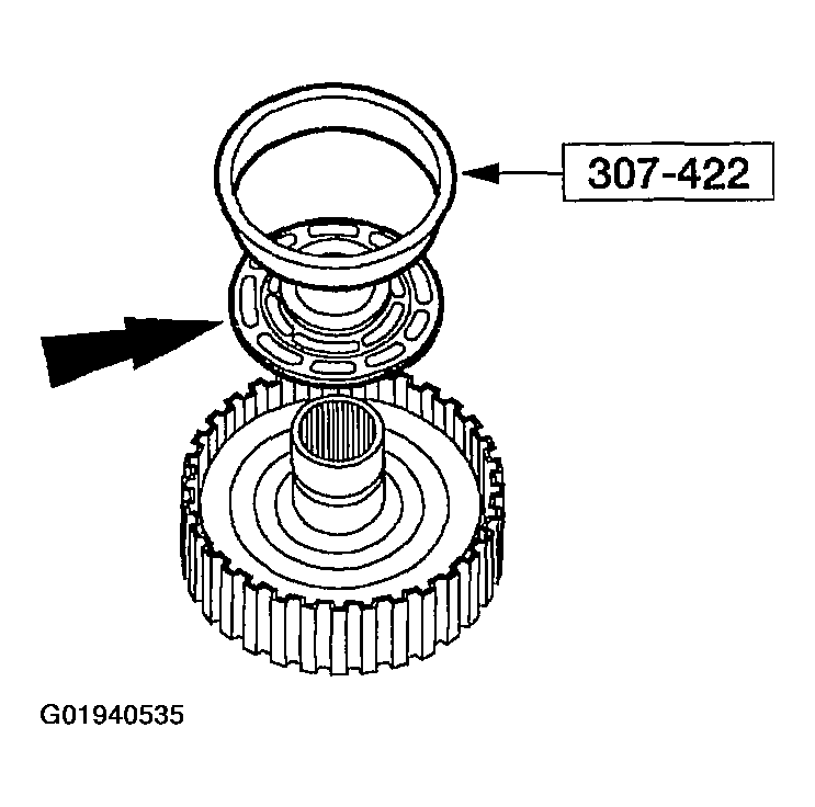
- Using the special tool, install the inner piston seal.
- Install the seal with sealing lip facing down.
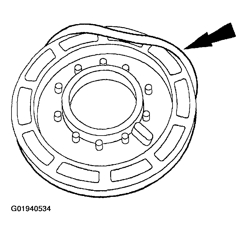
- Install the clutch piston outer seal so that when the piston is installed the sealing lip points toward the bottom of the cylinder.
- Using the special tool, install the direct clutch piston.
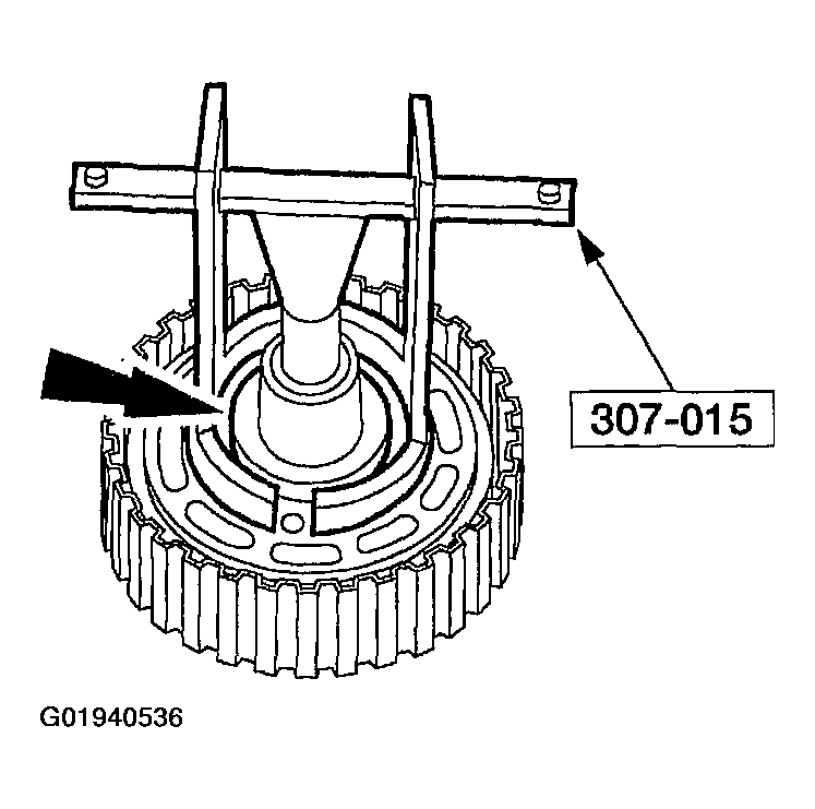
- Install the piston return spring and retainer assembly.
- Using the special tool, compress the piston return spring and install the retaining ring.
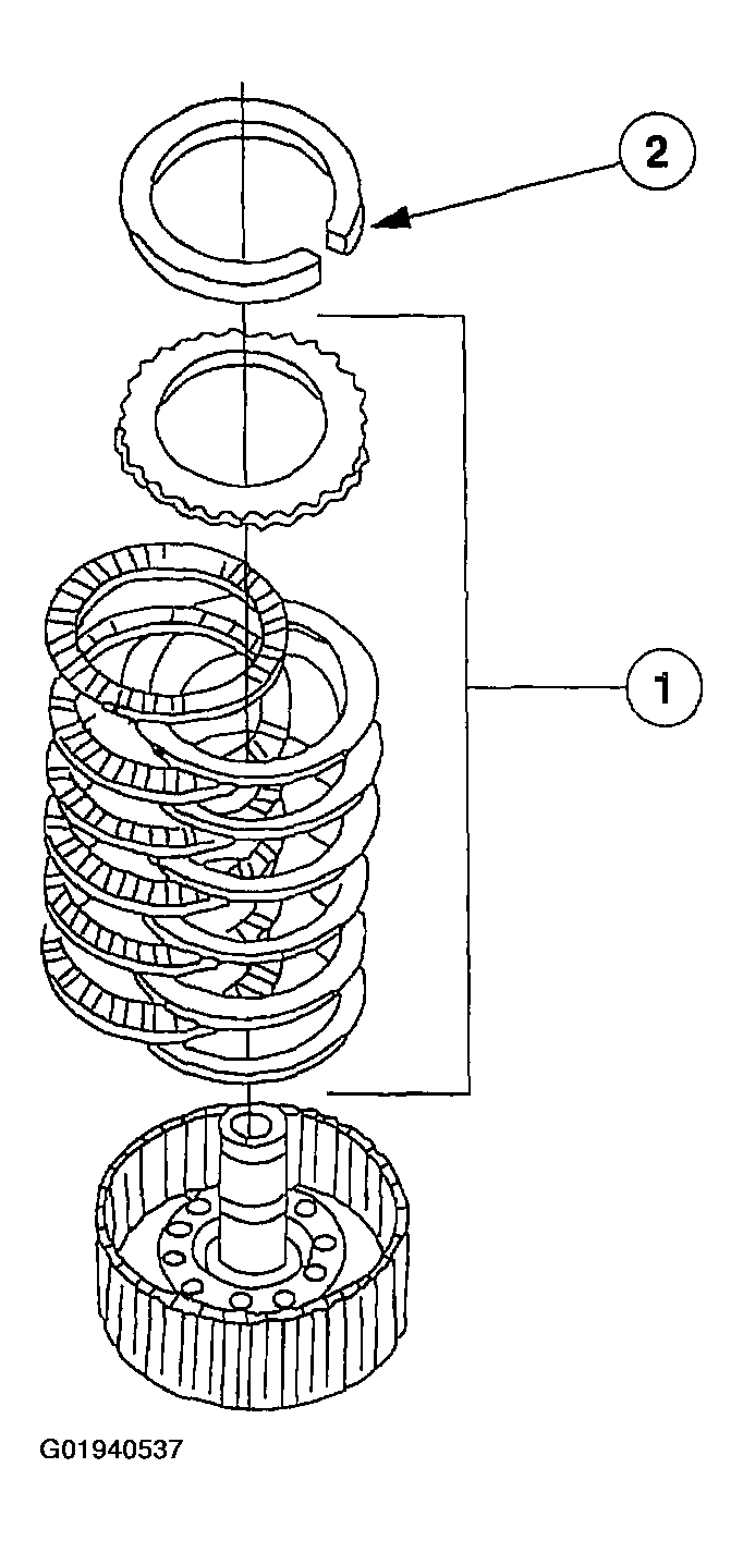
- Install the clutch pack retaining ring.
- Alternate external spline (steel) plates and internal spline (friction) plates, starting with a steel plate and ending with the friction plate.
- Install the clutch pack retaining ring.
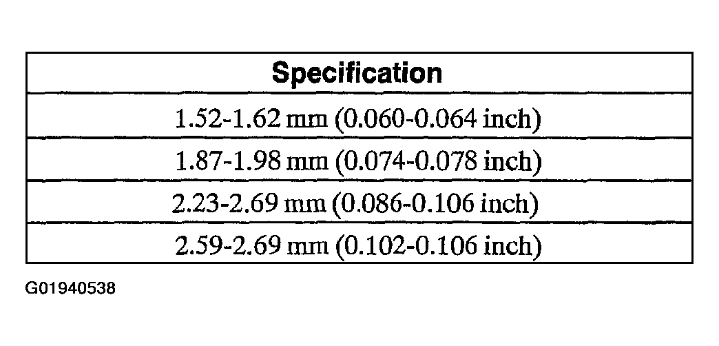
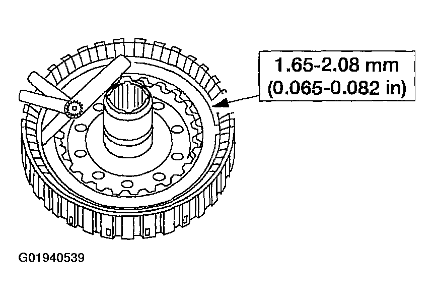
- Use a feeler gauge to check the clearance between the clutch pack selective retaining ring and the pressure plate.
- If the clearance is not within specifications, install the correct size retaining ring and recheck the clearance.
- Install the direct clutch hub.
- Install the No. 7 direct clutch inner bearing support.
- Install the direct clutch hub.
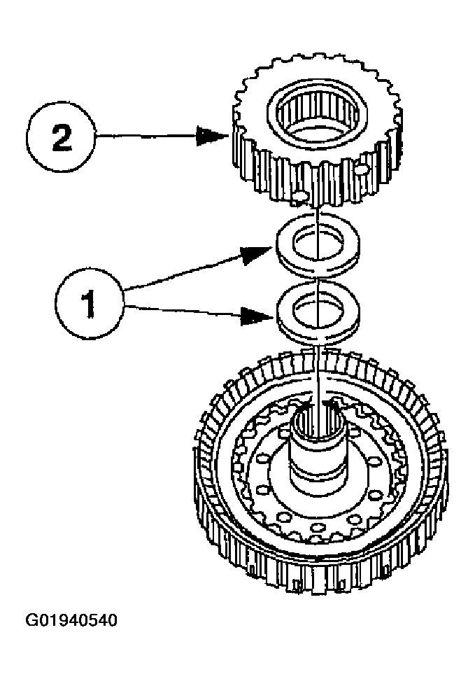 Courtesy of FORD MOTOR CO.NOTE: Inspect the output shaft bearing surfaces for scores. Inspect the output shaft splines for wear. Inspect all bushings.
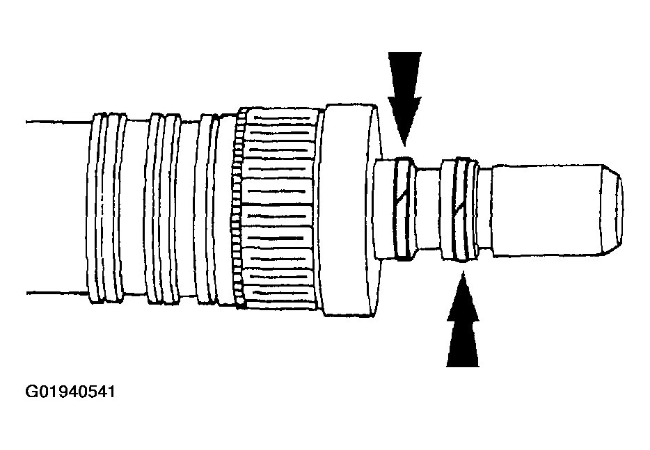
- Install the two direct clutch seal rings.
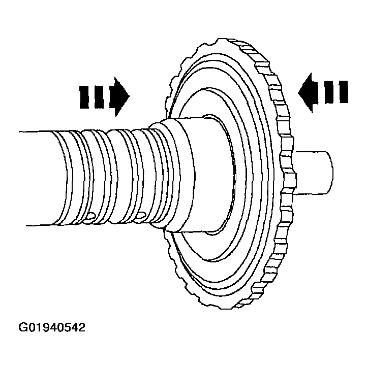
- Install the output shaft hub.
- Position the output shaft hub.
- Install the retaining ring.
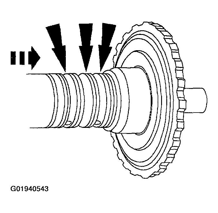
- Install the three output shaft seal rings.
- Install the No. 8 needle bearing on the direct clutch cylinder.
- Assemble the direct clutch on the output shaft.
- Align the index marks on output shaft and the output shaft ring gear and install the ring gear on the output shaft.
NOTE:
Lubricate direct clutch piston inner seal and seal protector with petroleum jelly.
NOTE:
Coat the inner and outer direct clutch piston seals, clutch cylinder sealing area and piston inner sealing area with petroleum jelly.
NOTE:
Before assembly, soak new clutch discs in clean automatic transmission fluid for 15 minutes.
CAUTION:
Make sure the seals are lapped correctly. Internal damage may occur.
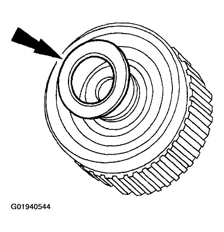
NOTE:
Direct clutch cylinder may be installed after the output shaft ring gear is installed to the output shaft hub.
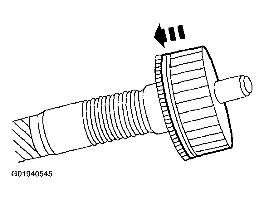
CAUTION:
The index mark on the output shaft must be aligned with the index mark on the output shaft ring gear.