Fluorescent Dye Injection - Using A Dye Injector Loop Kit
NOTE:
Before using the R-134a fluorescent dye injector for the first time, refer to the equipment manufacturers instructions on evacuation of non-condensable gasses from the hoses.
NOTE:
Refrigerant system pressure should be between 413-551 kPa (60-80 psi) at 24°C.
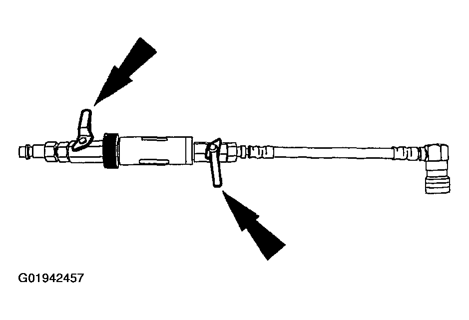
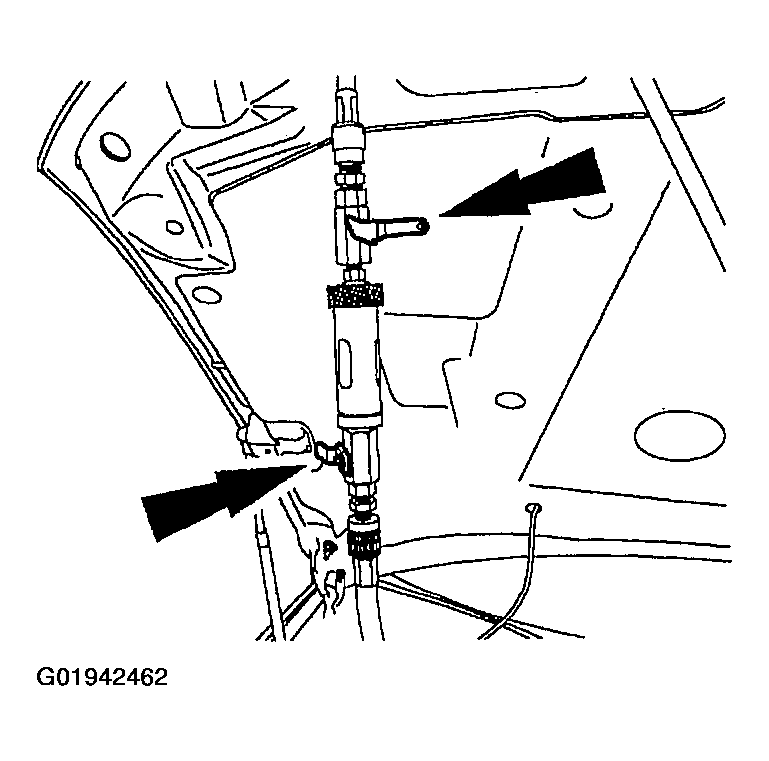
- Verify that the valves on the special tool are closed.
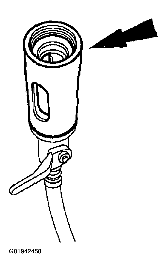
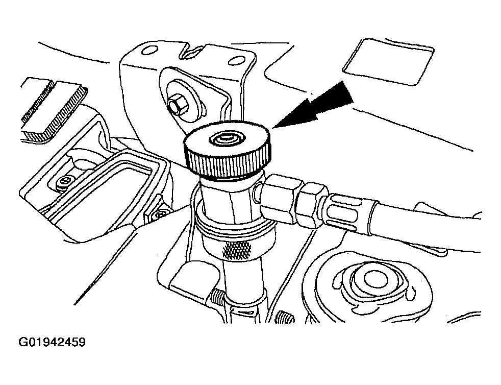
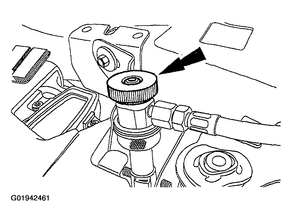
- Fill the special tool reservoir with 7 ml (0.25 oz) of fluorescent dye.
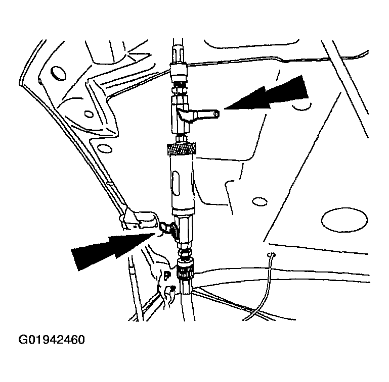
- Install the special tool between the high-pressure and low-pressure service gauge port valves.
- Start the engine.
- Open the high-pressure service valve.
- Open the special tool valves and inject the fluorescent dye into the refrigerant system.
- Close the high-pressure service valve to allow the pressure inside the special tool to equalize with the suction side of the refrigerant system.
- Close the valves on the special tool.
- Disconnect the high-pressure and low-pressure service valves and remove the special tool from the vehicle.
CAUTION:
Make sure all tools and hoses are clear of the engine cooling fan and drive belt before starting the engine.
NOTE:
Close the valves on the special tool while the A/C compressor is operating.
NOTE:
Leave all valves on the special tool closed when not in use.