Lack Of A/C Cooling - Restricted/Reduced Air Flow Through Vents - Evaporator Core Icing (04-19-11)
Publication date: 2004-10-04Reference number: 04-19-11
Supersedes refnos: 03-22-8
LACK OF A/C COOLING - RESTRICTED/REDUCED AIR FLOW THROUGH VENTS - EVAPORATOR CORE ICING
TECHNICAL SERVICE BULLETIN
| FORD: | 2000-2004 Crown Victoria |
| MERCURY: | 2000-2004 Grand Marquis |
DESCRIPTION
LACK OF A/C COOLING - RESTRICTED/REDUCED AIR FLOW THROUGH VENTS - EVAPORATOR CORE ICING
ISSUE
Some vehicles may exhibit a lack of A/C cooling and restricted/reduced air flow through the A/C vents typically during extended idling conditions. This may be due to extended A/C compressor operation (lack of compressor cycling) causing icing of the evaporator core surface.
ACTION
To service, first verify that the A/C clutch relay is operating properly and that the contacts are not sticking closed. The A/C clutch relay contacts may stick closed due to arcing. The arcing may be caused by transient voltage from the A/C clutch field coil when the relay contacts open to turn off the AC clutch. Refer to the following Service Procedure.
SERVICE PROCEDURE
- Monitor the powertrain control module (PCM) PIDS ACCS, WAC and high/low side refrigerant pressures. If WAC PID reads OFF, and the A/C compressor continuously operates, check for A/C Relay contacts sticking closed.
- A/C relay contacts that are sticking closed will have continuity between relay pins 30 and 87. If continuity is found replace the A/C relay (2000-2002 FOAZ-14N089-A or 2003-2004 F5TZ-14N089-B). It will also be necessary to add a 400V 1.0A Diode (E8DZ-10C912-A) from circuit 57 BK to circuit 321 GY/WH. (SEE DIODE INSTALLATION BELOW).
- If the A/C relay contacts are not sticking closed, then do not continue with this TSB. Perform normal diagnosis using wiring diagrams and Workshop Manual procedures.
- If the ACCS PID reads ON with low side refrigerant pressures below 20 PSI, diagnose for a faulty cycling switch or shorted circuits.
- On 2000-2002 model years the low pressure cycling switch was used to control system operation. For these model years replacement of the low pressure cycling with one that has a higher set point can also reduce the potential for ice build up on the evaporator core. For 2000-2002 model years only, replace the white A/C low pressure cycling switch with black low pressure cycling switch (F5VY-19E561-A) per Workshop Manual Section 412-03.
DIODE INSTALLATION
- Disconnect the battery positive terminal.
- Disconnect female connector C128 (2000-2001 model years) or female connector C1033 (2002-2004 model years) on the engine harness.
- Identify circuit 57 (BK) pin location 10 and circuit 321 (GY/WH) pin location 7 (pin location 8 on Natural Gas Vehicle (NGV)).
- Remove circuits 57 and 321 from the connector.
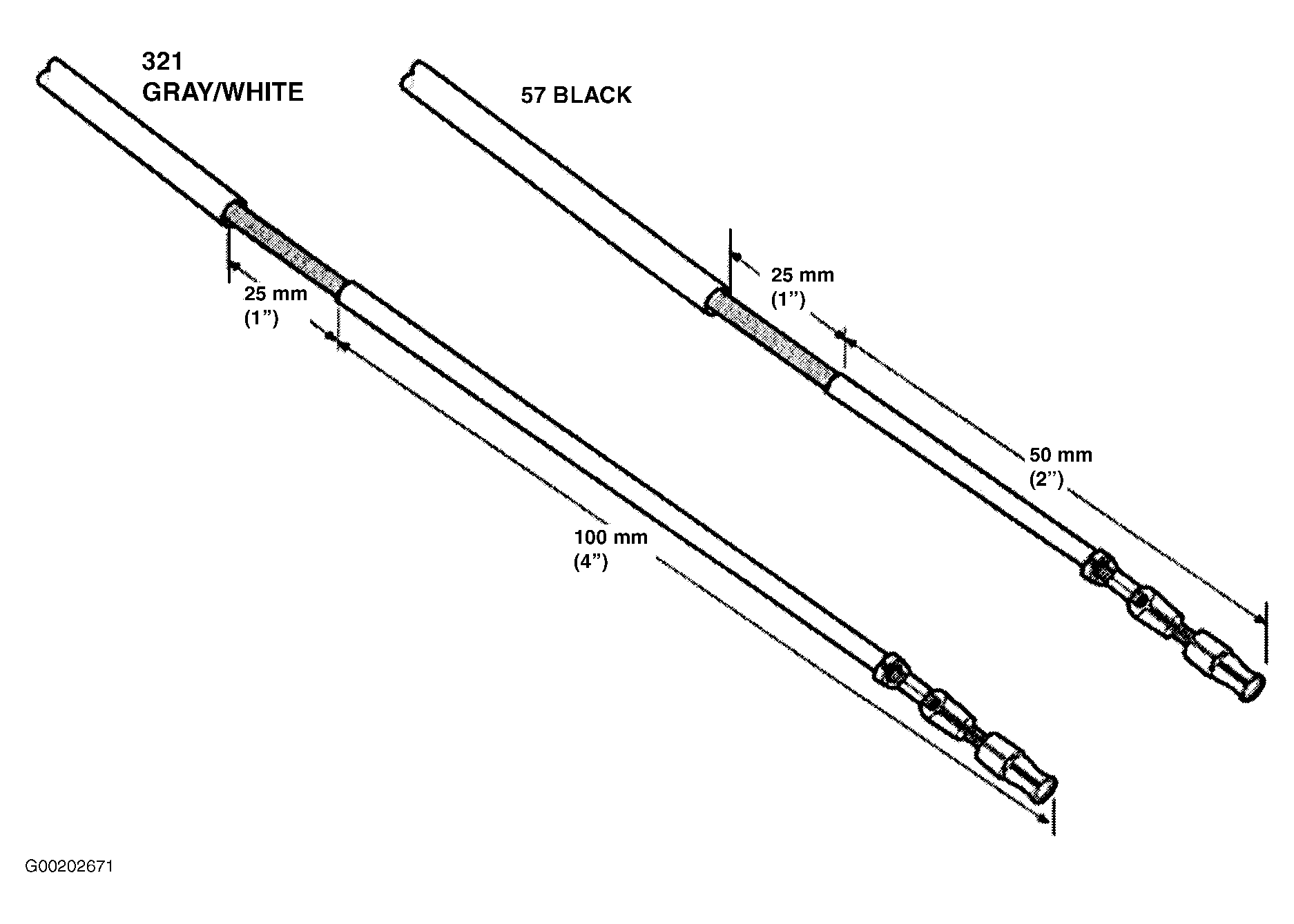
- Strip 25 mm (1") of insulation away from circuit 57 approximately 50 mm (2") from the connector (Fig 1 ).
- Strip 25 mm (1") of insulation away from circuit 321 approximately 100 mm (4") from the connector (Fig 1 ).
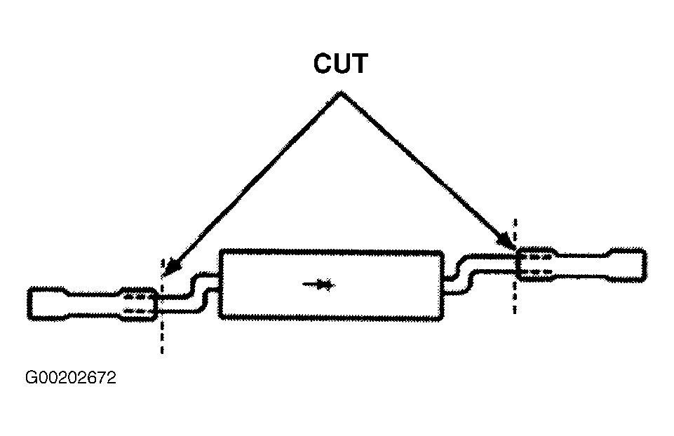
- Cut the butt connectors from the diode and strip approximately 32 mm (1.25") of insulation from the cut ends of the wires (Fig 2 ).
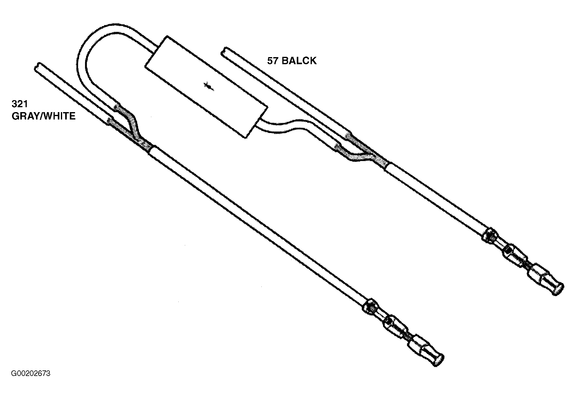
- Twist the ends of the diode wires around the exposed wire on circuits 57 and 321 (Fig 3
).NOTE: THE DIODE MUST BE INSTALLED TO ALLOW CURRENT FLOW FROM CIRCUIT 57 TO CIRCUIT 321 (THE ARROW ON THE DIODE MUST POINT FROM CIRCUIT 57 TO CIRCUIT 321). ORIENT THE DIODE WIRES AWAY FROM THE TERMINAL ENDS OF CIRCUITS 57 AND 321 AS SHOWN IN THE ILLUSTRATIONS THIS WILL ALLOW HEAT SHRINK TUBING TO BE SLIPPED ON THE WIRES.
- Solder the diode wires to circuits 57 and 321. Use rosin core mildly activated (RMA) solder. DO NOT USE ACID CORE SOLDER.
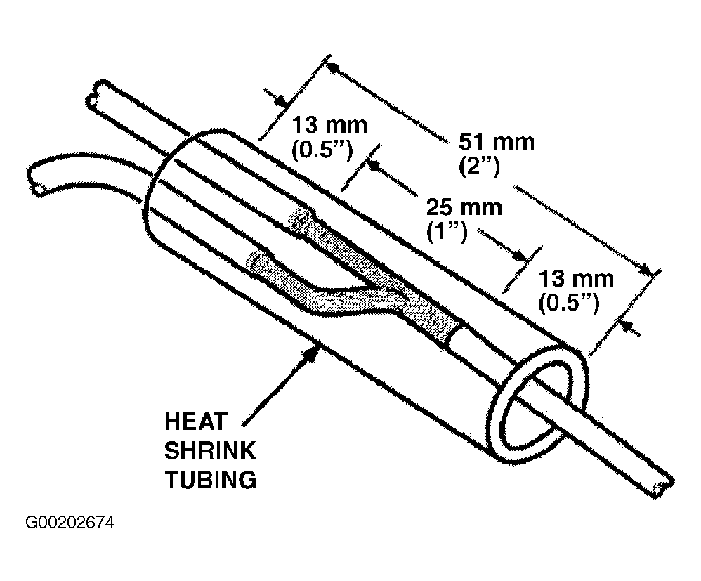
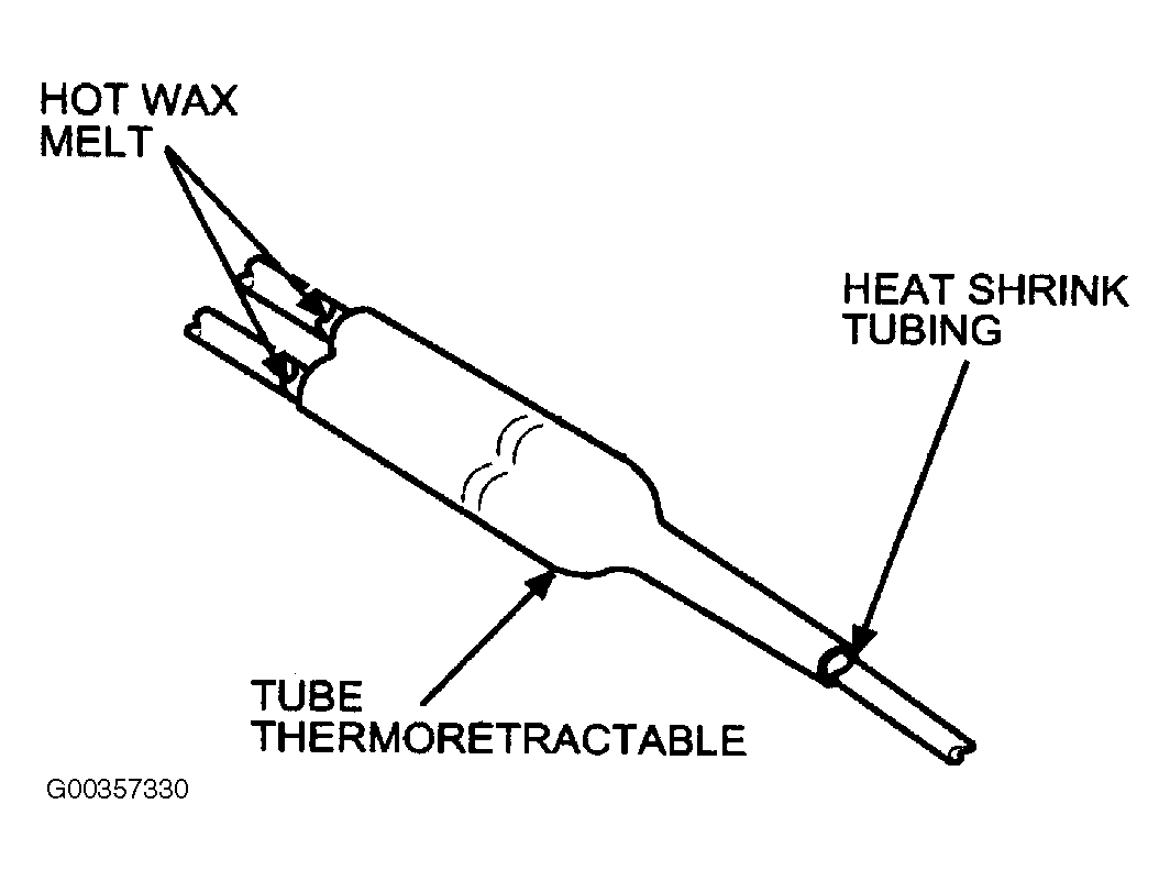
- Slip Dual Wall Heat Shrink Tubing (Motorcraft part # WT-5627-A) containing hot melt wax up the terminal ends of circuits 57 and 321 over the exposed wire.NOTE: IT IS IMPORTANT TO USE HEAT SHRINK TUBING CONTAINING HOT MELT WAX OVER A SOLDERED CIRCUIT JOINT TO CREATE A WATERPROOF AND AIRTIGHT CONNECTION. MAKE SURE THAT THE TUBING COVERS ALL EXPOSED WIRES PLUS AT LEAST A HALF INCH AT BOTH ENDS (Fig 4 ).
- Heat the entire length of the heat shrink tubing until the hot melted wax appears from both ends of the tubing (Fig 5 ).
- Reconnect connector C128 or C1033 (as applicable).
- Reconnect the battery and test the circuit for correct A/C operation.
PARTS INFORMATION
| Part Number | Part Name |
|---|---|
| FOAZ-14N089-A | Relay (2000-2002 MY) |
| F5TZ-14N089-B | Relay (2003-2004 MY) |
| E8DZ-10C912-A | Diode |
| F5VY-19E561-A | Pressure Cycling Switch |
| WT-5627-A | Shrink Wrap |
WARRANTY INFORMATION
WARRANTY STATUS: Eligible Under Provisions Of New Vehicle Limited Warranty Coverage.
| Operation | Description | Time |
|---|---|---|
| 041911A | Replace A/C Clutch Relay And Install Diode (Includes Time To Monitor PIDS And Replace Low Pressure Switch If Necessary Does Not Include Time For Diagnosis Outside Of TSB Or Wiring Shorts) | 0.9 Hr. |
| Basic Part No. | Condition Code |
|---|---|
| 14N089 | 42 |