Drive Pinion Flange & Drive Pinion Seal: Removal
- Remove the rear wheel and tire assemblies.
- Remove the rear brake discs. For additional information, refer to REAR BRAKE ROTOR .
- Index-mark the driveshaft flange and pinion flange for correct alignment during installation.
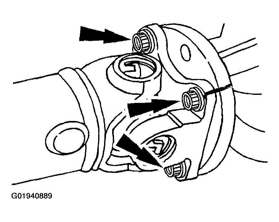
- Remove the four bolts.
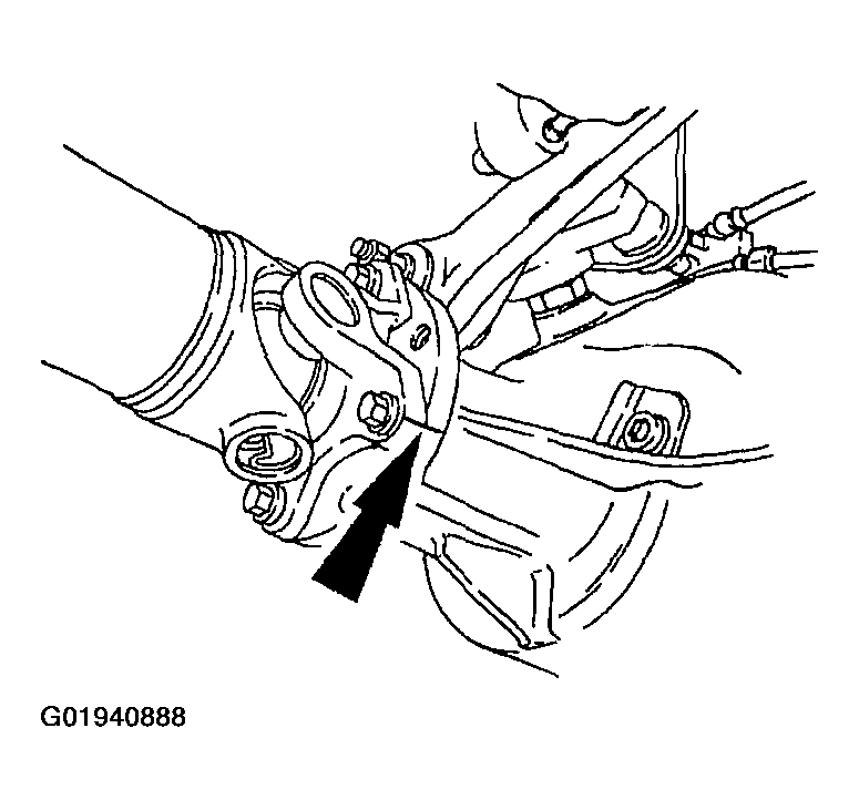
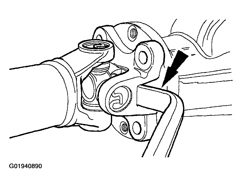
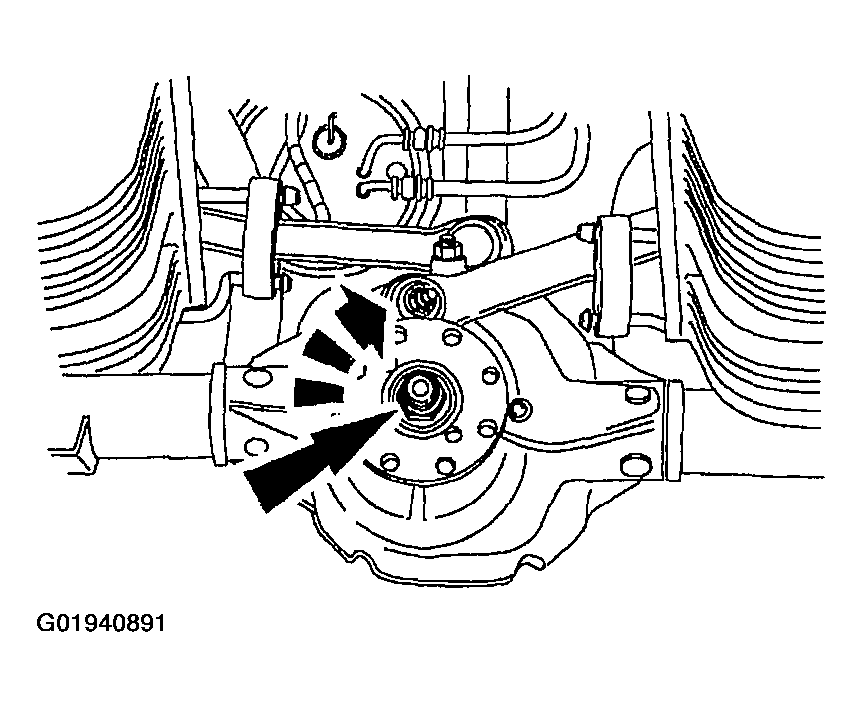
- Using a suitable tool as shown, disconnect the driveshaft centering socket yoke from the rear axle pinion flange.
- Position the driveshaft aside.
- Install a N.m (inch-pound) torque wrench on the nut and record the torque necessary to maintain rotation of the pinion through several revolutions.
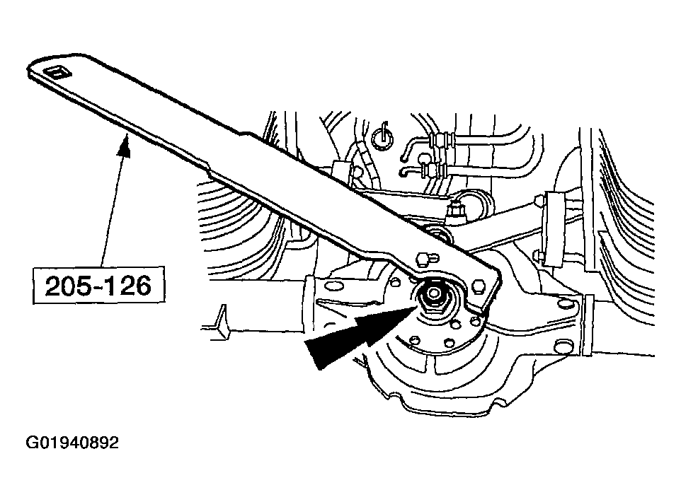
- Use the special tool to hold the pinion flange while removing the nut.
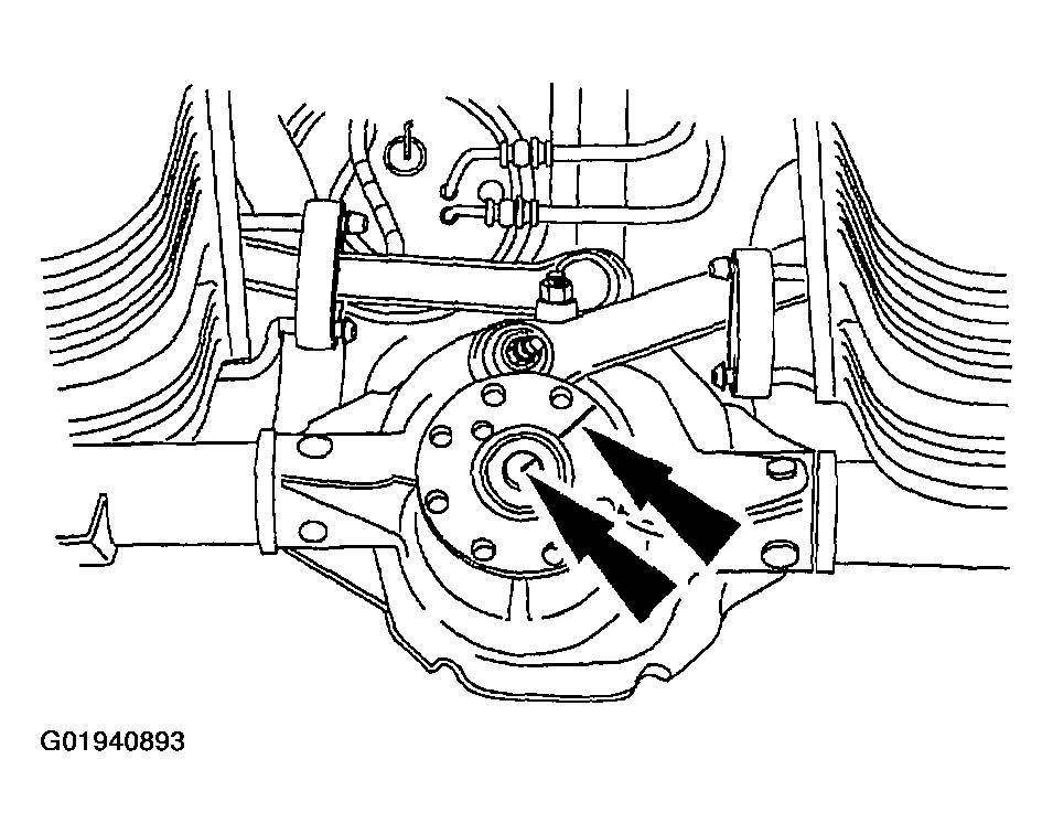
- Index-mark the pinion flange and the drive pinion stem for correct alignment during installation.
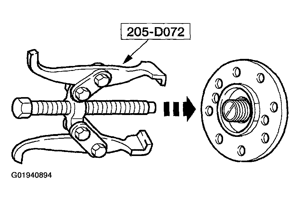
- Using the special tool, remove the pinion flange.
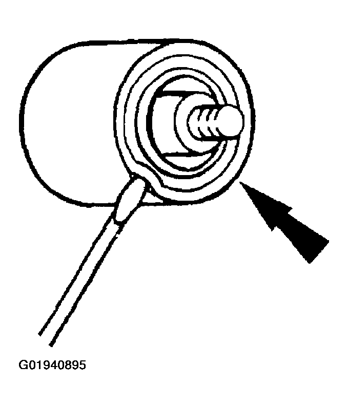
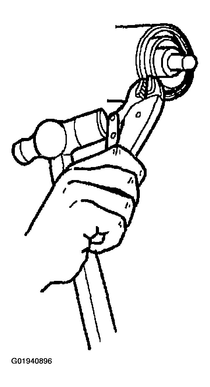
- Using a screwdriver, force the rear axle drive pinion seal metal flange up and strike it with a hammer.
- Using gripping pliers and a hammer, remove the seal.
WARNING:
The electrical power to the air suspension system must be shut off prior to hoisting, jacking or towing an air suspension vehicle. This can be accomplished by turning off the air suspension switch located in the RH kick panel area. Failure to do so can result in unexpected inflation or deflation of the air springs, which can result in shifting of the vehicle during these operations.
CAUTION:
Remove the rear brake discs to prevent brake drag during drive pinion bearing preload adjustment.
CAUTION:
The driveshaft centering socket yoke fits tightly on the rear axle pinion flange pilot. Never hammer on the driveshaft or any of its components to disconnect the yoke from the flange. Pry only in the area shown with a suitable tool to disconnect the yoke from the flange.
 Courtesy of FORD MOTOR CO.
CAUTION:
Discard the nut after removing it. Install a new nut during installation.