Drive Pinion Flange & Drive Pinion Seal: Installation
- Coat the new rear axle drive pinion seal lips with lubricant.
- Use Premium Long-Life Grease XG-1-C or equivalent meeting Ford specifications ESA-M1C75-B.
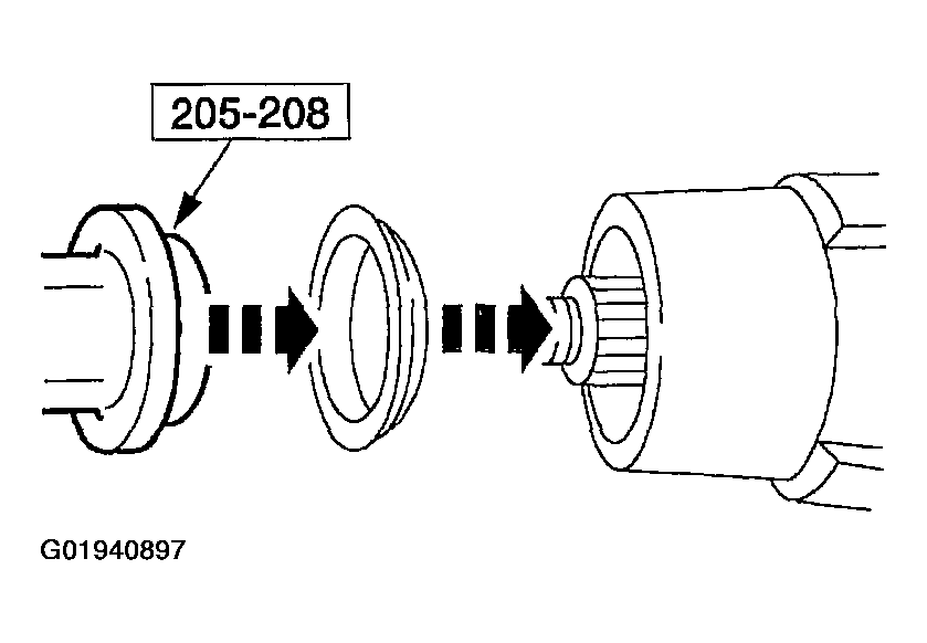
- Using the special tool, install the rear axle drive pinion seal.
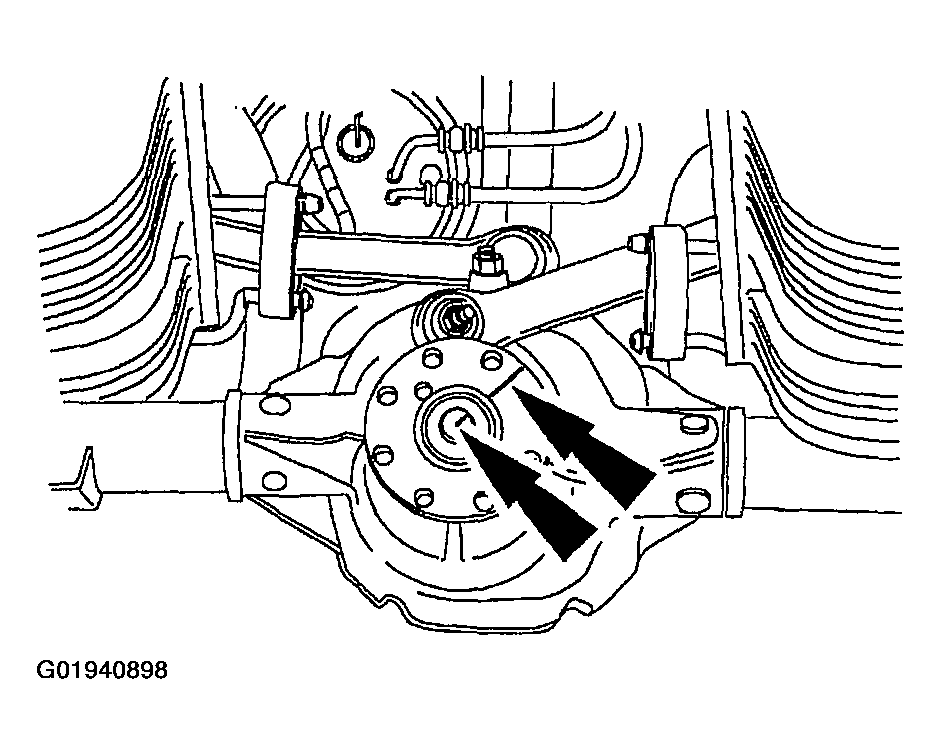
- Lubricate the pinion flange splines.
- Use SAE 80W-90 Premium Rear Axle Lubricant XY-80W90-QL or equivalent meeting Ford specification WSP-M2C197-A.
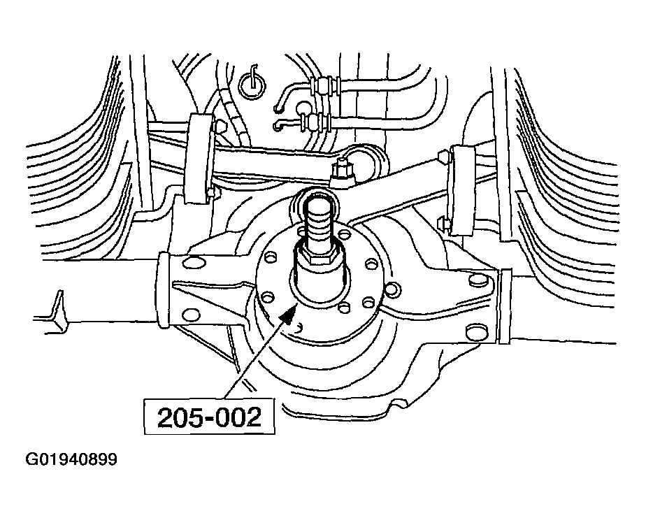
- Position the pinion flange.
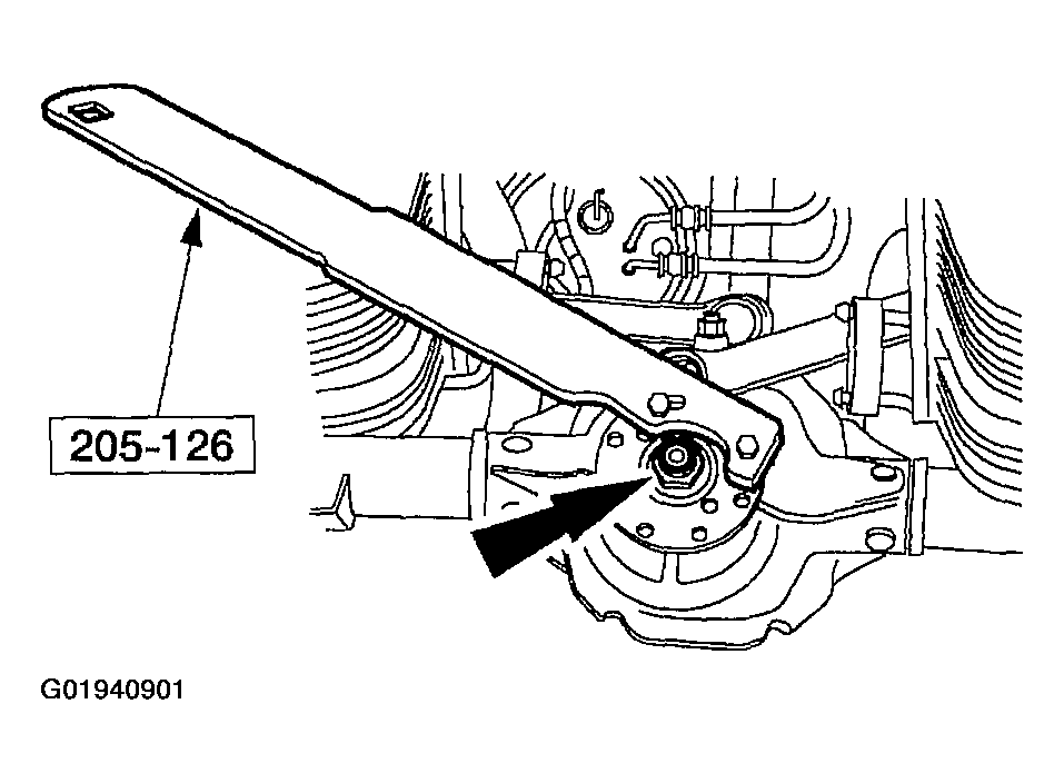
- Using the special tool, install the pinion flange.
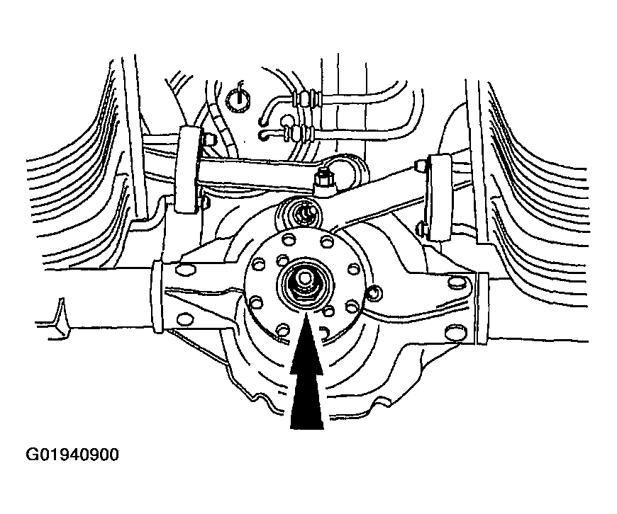
- Position the new nut.
- Use the special tool to hold the pinion flange while tightening the nut.
- Rotate the pinion occasionally to make sure the differential pinion bearings seat correctly. Take frequent differential pinion bearing preload readings by rotating the pinion with a N.m (inch-pound) torque wrench.
- If the preload recorded prior to disassembly is lower than the specification for used bearings, tighten the nut to specification. If the preload recorded prior to disassembly is higher than the specification for used bearings, tighten the nut to the original reading as recorded.
- Refer to torque specifications for used pinion bearings in SPECIFICATIONS .
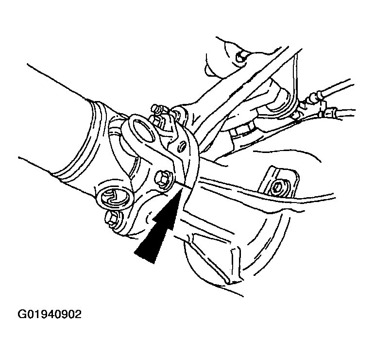
- Align the index marks.
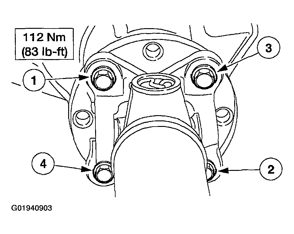
- Install the driveshaft.
- Install the rear brake discs and calipers. For additional information, refer to REAR BRAKE ROTOR .
- Install the rear wheel and tire assemblies.
CAUTION:
Installation without the correct tool can result in early seal failure.
CAUTION:
If the rear axle drive pinion seal becomes misaligned during installation, remove the seal and install a new seal.
 Courtesy of FORD MOTOR CO.
NOTE:
Disregard the index marks if installing a new pinion flange.
CAUTION:
Do not under any circumstance loosen the nut to reduce preload. If it is necessary to reduce preload, install a new collapsible spacer and nut.
CAUTION:
Remove the special tool while taking preload readings with the N.m (inch-pound) torque wrench.
CAUTION:
The driveshaft centering socket yoke fits tightly on the rear axle pinion flange pilot. To ensure that the yoke seats squarely on the flange, tighten the bolts evenly in a cross pattern as shown.
NOTE:
If equipped with air suspension, reactivate the system.