Removal & Installation
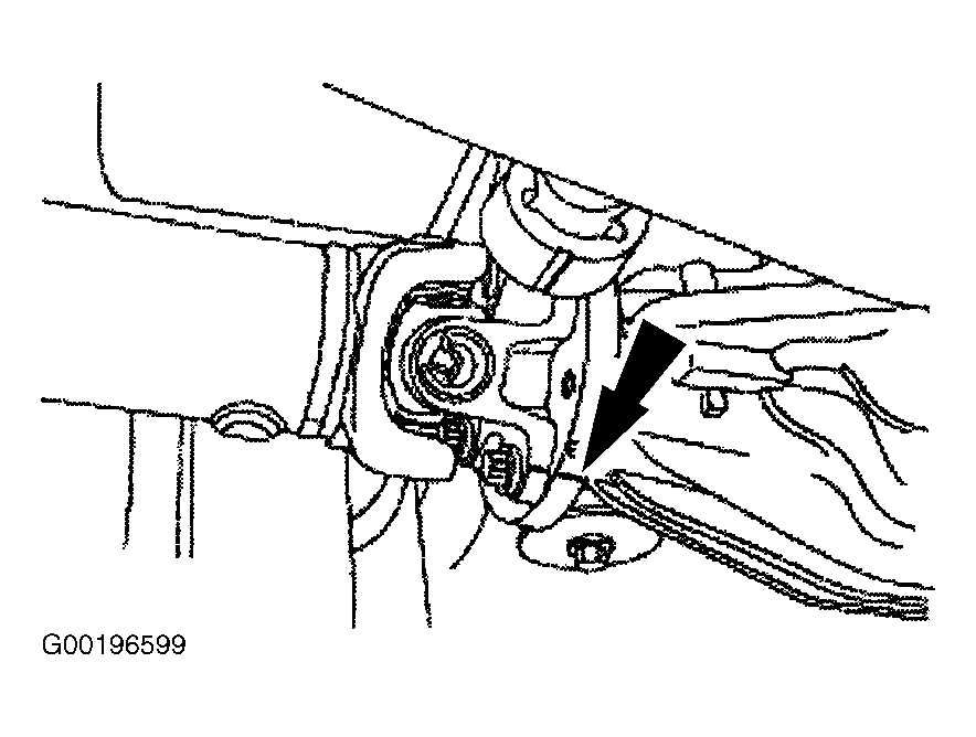
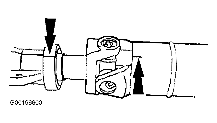
- Raise and support the vehicle. Index mark the drive shaft centering socket flange to the rear axle pinion flange. See Fig 1 . Index mark the drive shaft slip yoke and the transmission output shaft. See Fig 2 . Remove the 4 differential pinion flange bolts.
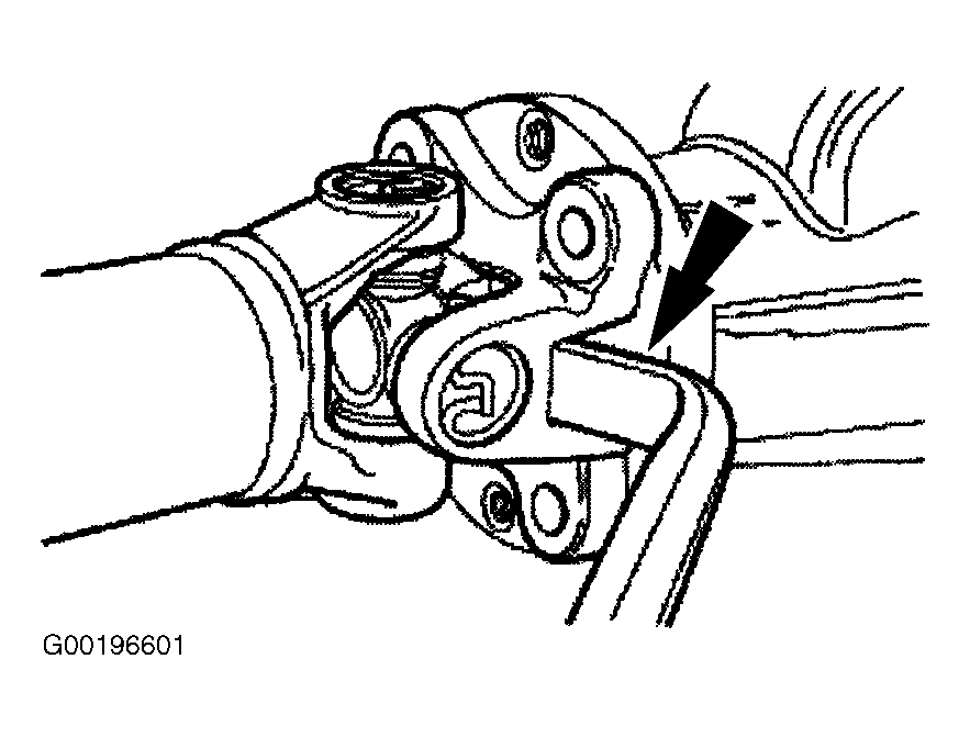
- Using a suitable tool, disconnect the drive shaft centering socket flange from the differential pinion flange. Pry only in the area shown, with a suitable tool, to disconnect the drive shaft centering socket flange from the differential pinion flange. See Fig 3 .
- Make sure the index marks on the extension housing and drive shaft are aligned before separation. Place a suitable drain pan under transmission to catch fluid. Lower the drive shaft and separate it from the transmission.
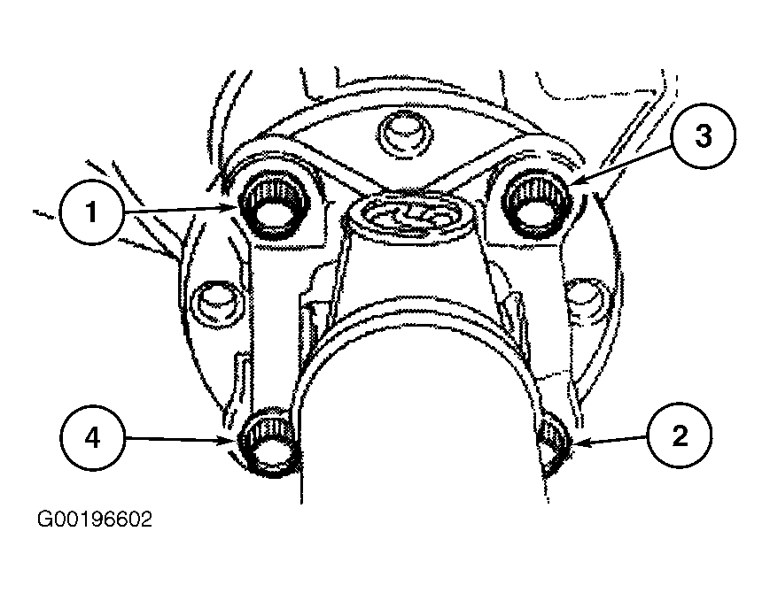
- To install, reverse the removal procedure. The drive shaft centering socket flange fits tightly on the differential pinion flange. To make sure that the drive shaft centering socket flange seats squarely on the differential pinion flange, tighten the bolts evenly, to specification in a crisscross pattern as shown. See Fig 4 . See TORQUE SPECIFICATIONS .
- Fill transmission to proper level with appropriate fluid. See AUTOMATIC TRANSAXLE/TRANSMISSION - 4R70W article for Crown Victoria & Grand Marquis or SERVICING - A/T article for Town Car.
NOTE:
The drive shaft centering socket flange fits tightly on the differential pinion flange. Never hammer on the drive shaft or any of its components to disconnect the drive shaft centering socket flange from the differential pinion flange.