LEMON Manuals: Even more car manuals for everyone: 1960-2025
Home >> Ford >> 2002 >> Crown Victoria Base, 4.6 9 >> Repair and Diagnosis (Single Page) >> Engine Mechanical >> Mechanical >> Engine - 4.6L >> In-Vehicle Repair >> Intake Manifold - Gasoline Engines >> Removal

Intake Manifold - Gasoline Engines: Removal

  1. Disconnect the battery ground cable.
  2. Drain the engine cooling system.
  3. Remove the air cleaner outlet tube.
  4. Disconnect the fuel lines. For additional information, refer to FUEL SYSTEMS .
  5. Remove the wiper mounting arm and pivot shaft. For additional information, refer to MOUNTING ARM AND PIVOT SHAFT .
  6. Remove the drive belt.
  7. Raise the vehicle on a hoist.
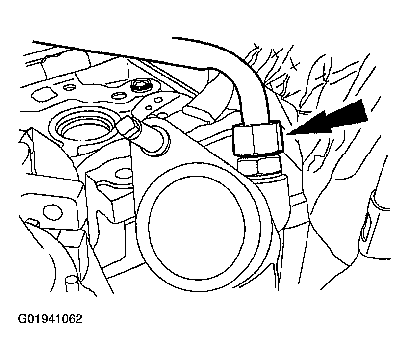
  8. Disconnect the exhaust gas recirculation (EGR) tube from the exhaust manifold.
    Fig 1: Identifying Exhaust Gas Recirculation (EGR) Tube
    G01941062Courtesy of FORD MOTOR CO.
  9. Lower the vehicle.
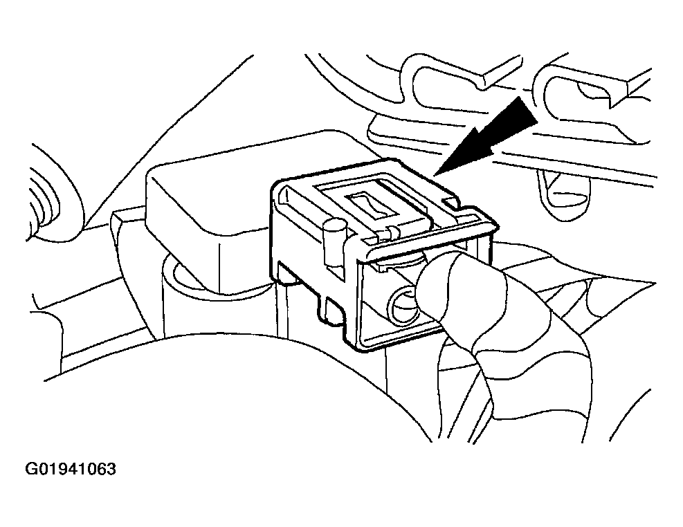
  10. Disconnect the differential pressure feedback EGR system electrical connector.
    Fig 2: Identifying Differential Pressure Feedback EGR System Electrical Connector
    G01941063Courtesy of FORD MOTOR CO.
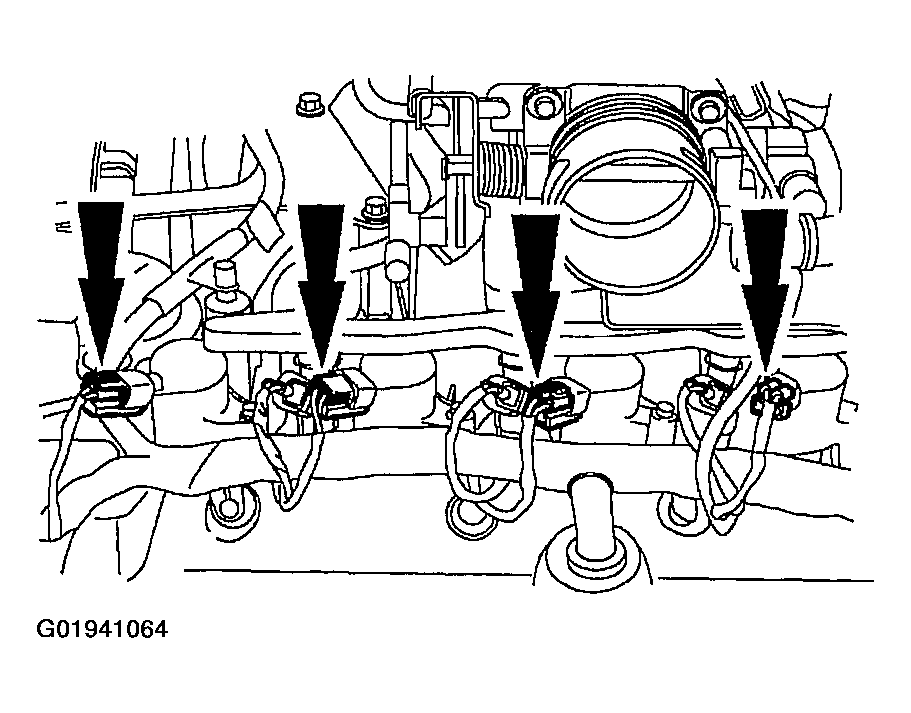
  11. Disconnect the fuel charging wiring electrical connectors from the eight ignition coils.
    Fig 3: Disconnecting Fuel Charging Wiring Electrical Connectors From Ignition Coils
    G01941064Courtesy of FORD MOTOR CO.
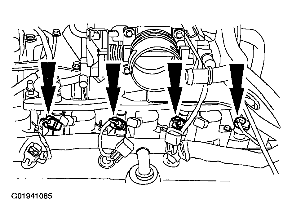
  12. Disconnect the fuel charging wiring electrical connectors from the eight fuel injectors.
    Fig 4: Disconnecting Fuel Charging Wiring Electrical Connectors From Fuel Injectors
    G01941065Courtesy of FORD MOTOR CO.
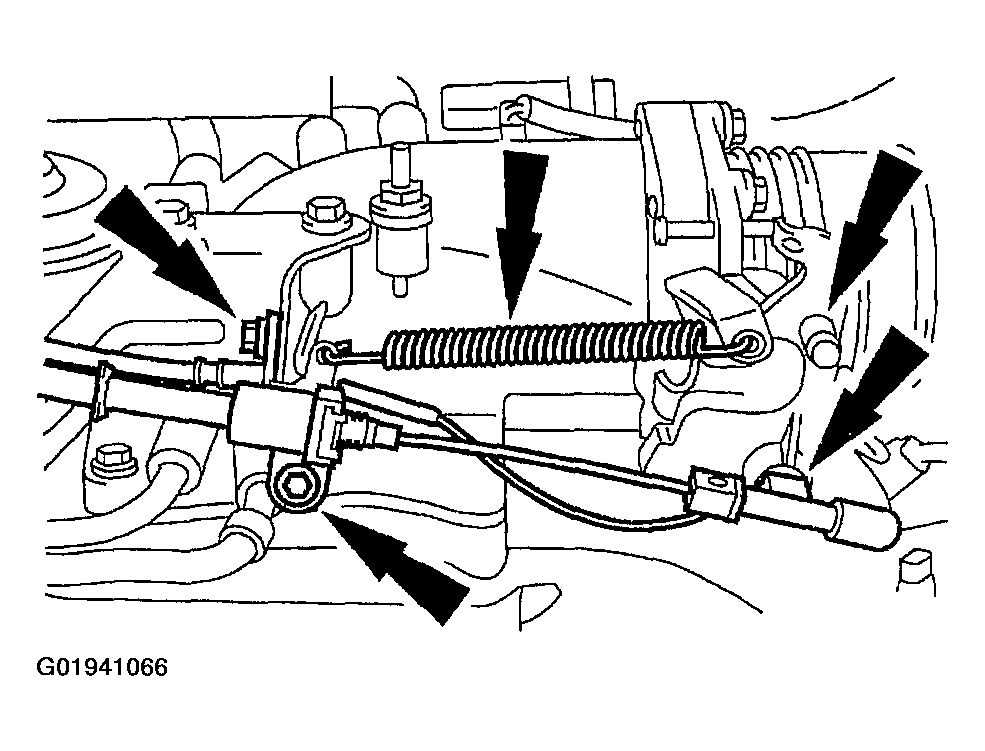
  13. Disconnect the accelerator cable, the speed control actuator cable and the throttle return spring.
    Fig 5: Identifying Accelerator Cable, Speed Control Actuator Cable & Throttle Return Spring
    G01941066Courtesy of FORD MOTOR CO.
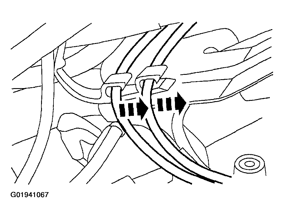
  14. Remove the cables from the EGR tube heat shield and position out of the way.
    Fig 6: Removing Cables From EGR Tube Heat Shield
    G01941067Courtesy of FORD MOTOR CO.
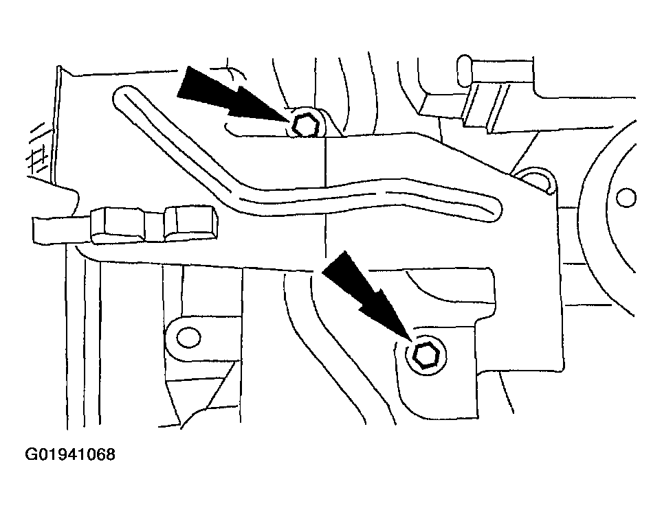
  15. Remove the bolts and the EGR tube heat shield.
    Fig 7: Identifying EGR Tube Heat Shield Bolts
    G01941068Courtesy of FORD MOTOR CO.
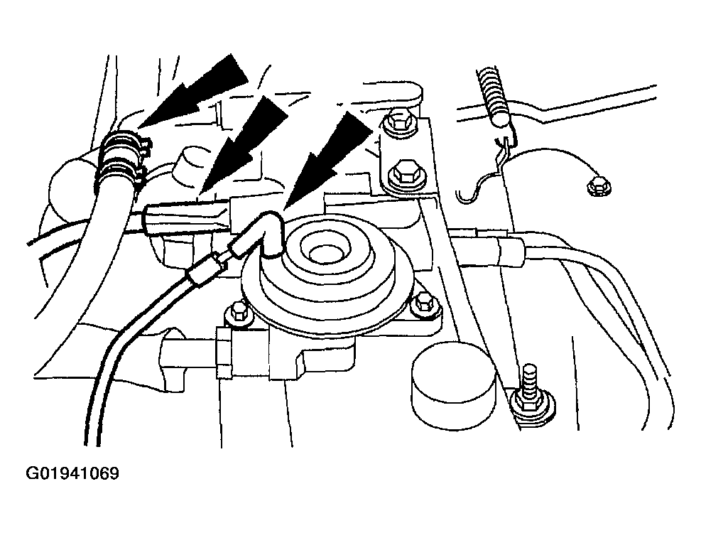
  16. Disconnect the evaporative emissions (EVAP) return tube, the main chassis vacuum supply hose, and the EGR valve vacuum supply hose.
    Fig 8: Identifying Evaporative Emissions (EVAP) Return Tube, Main Chassis Vacuum Supply Hose, & EGR Valve Vacuum Supply Hose
    G01941069Courtesy of FORD MOTOR CO.
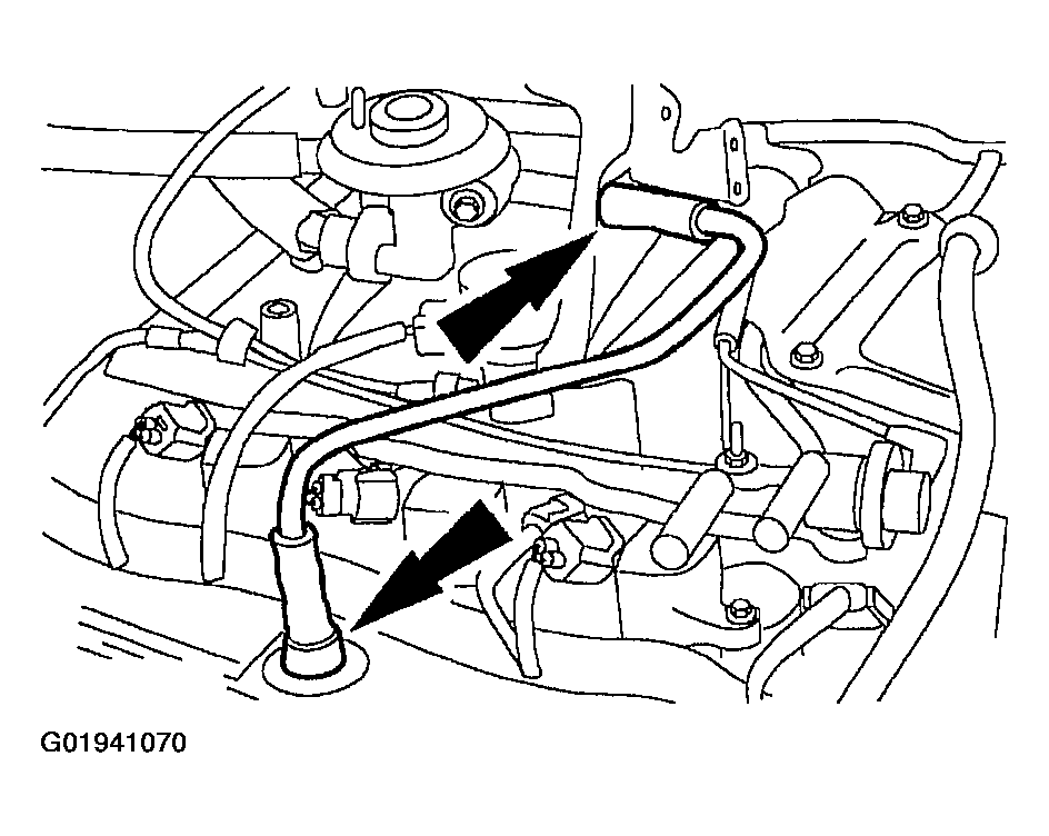
  17. Disconnect the positive crankcase ventilation (PCV) tube assembly at two locations and remove.
    Fig 9: Identifying Positive Crankcase Ventilation (PCV) Tube Assembly
    G01941070Courtesy of FORD MOTOR CO.
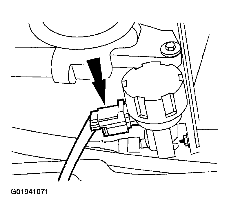
  18. Disconnect the electrical connector from the EGR vacuum regulator solenoid.
    Fig 10: Identifying EGR Vacuum Regulator Solenoid Electrical Connector
    G01941071Courtesy of FORD MOTOR CO.
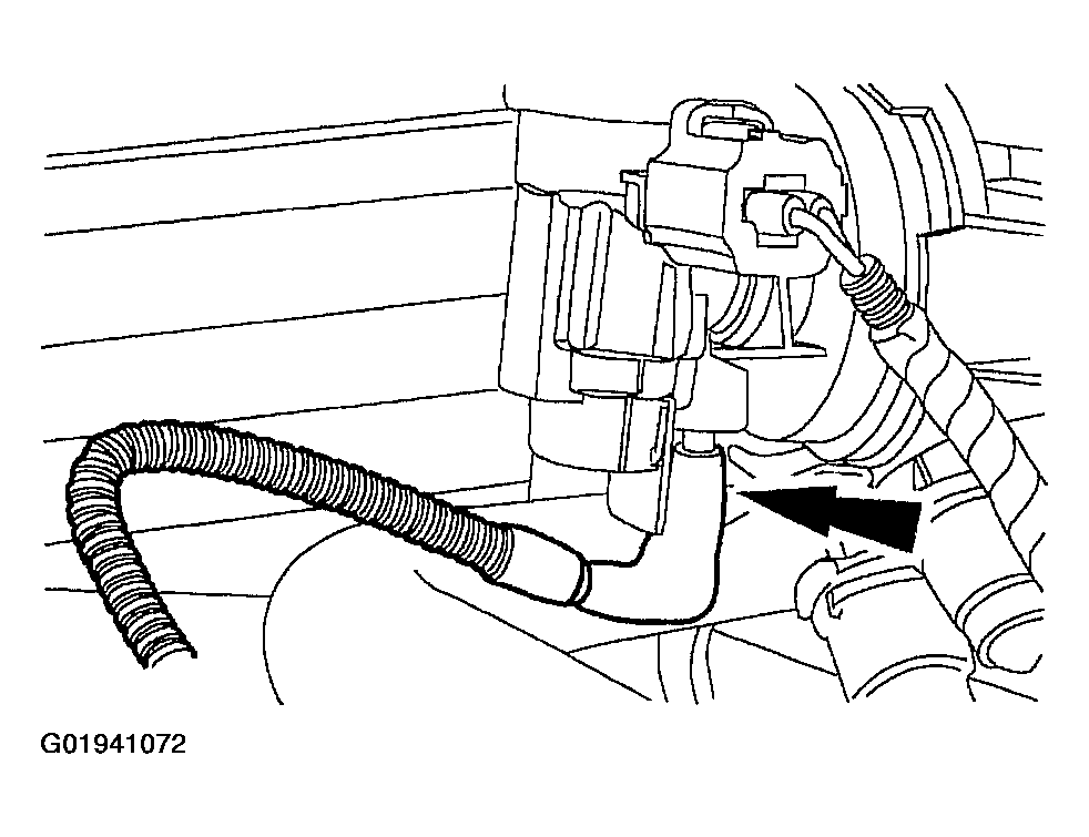
  19. Disconnect the vacuum line from the EVAP canister purge valve.
    Fig 11: Identifying EVAP Canister Purge Valve Vacuum Line
    G01941072Courtesy of FORD MOTOR CO.
  20. Disconnect the generator cable, the electrical connector and the harness pin-type retainer.
    Fig 12: Identifying Generator Cable, Electrical Connector & Harness Pin-Type Retainer
    G01941073Courtesy of FORD MOTOR CO.
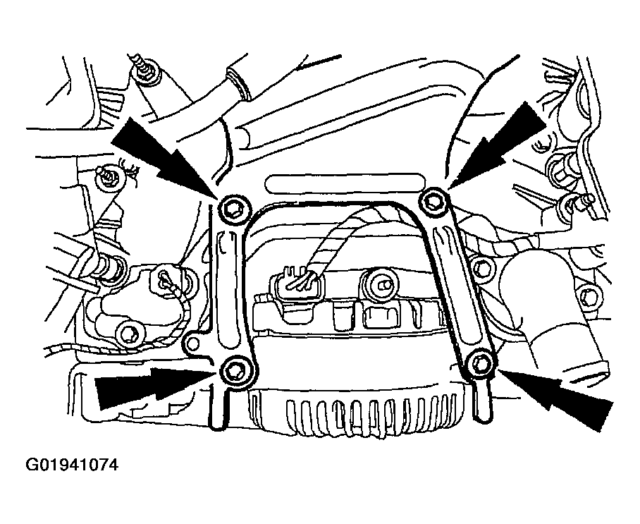
  21. Remove the bolts and the generator mounting bracket.
    Fig 13: Identifying Generator Mounting Bracket Bolts
    G01941074Courtesy of FORD MOTOR CO.
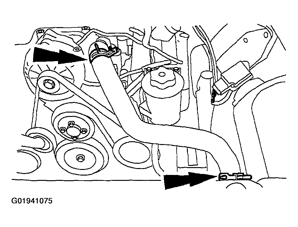
  22. Remove the upper radiator hose.
    Fig 14: Identifying Upper Radiator Hose Clamps
    G01941075Courtesy of FORD MOTOR CO.
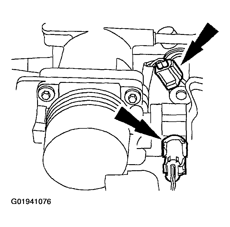
  23. Disconnect the electrical connector from the idle air control (IAC) valve and the throttle position (TP) sensor.
    Fig 15: Identifying Idle Air Control (IAC) Valve & Throttle Position (TP) Sensor Electrical Connectors
    G01941076Courtesy of FORD MOTOR CO.
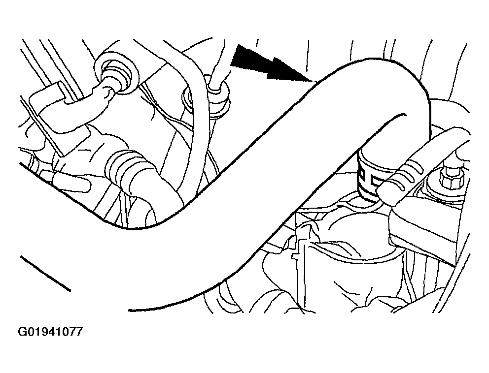
  24. Disconnect the heater water hose.
    Fig 16: Identifying Heater Water Hose
    G01941077Courtesy of FORD MOTOR CO.
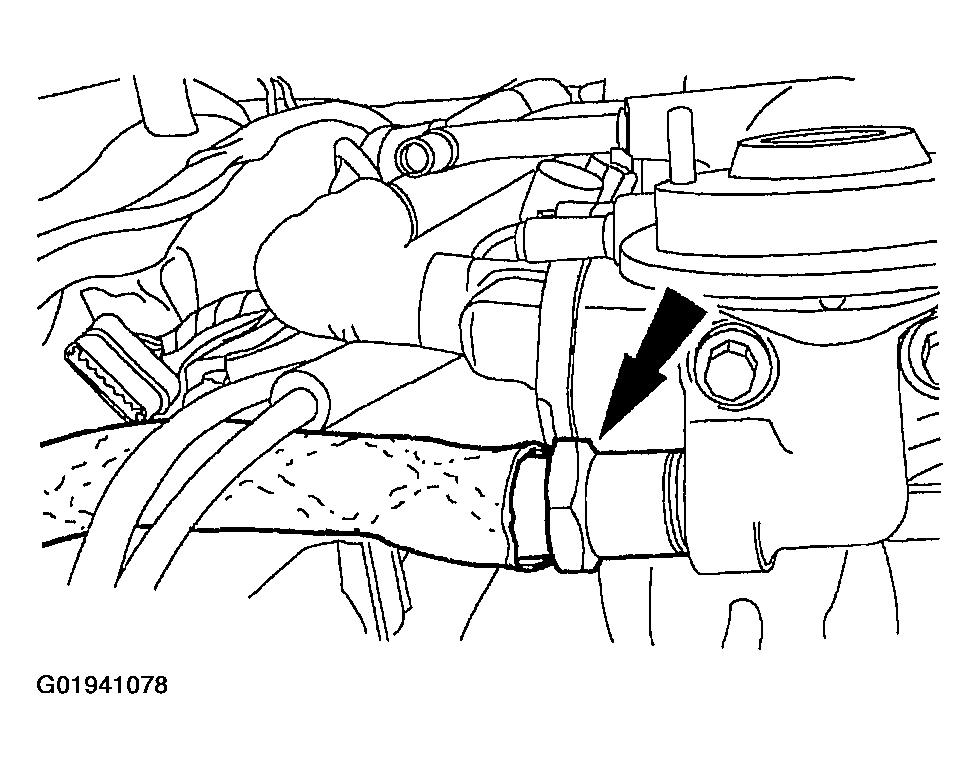
  25. Disconnect the EGR tube nut from the EGR valve.
    Fig 17: Identifying EGR Tube Nut
    G01941078Courtesy of FORD MOTOR CO.
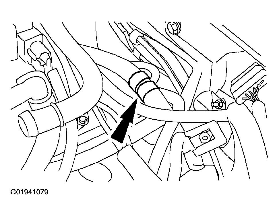
  26. Separate the fuel charging wiring harness pin-type retainer from the crash bracket.
    Fig 18: Identifying Fuel Charging Wiring Harness Pin-Type Retainer & Crash Bracket
    G01941079Courtesy of FORD MOTOR CO.
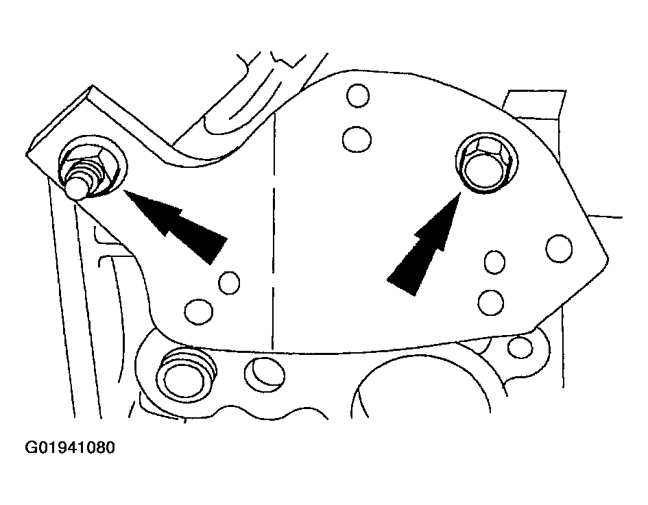
  27. NOTE: The LH heated oxygen sensor and the transmission electrical connectors are attached to the wiring bracket and must be separated from the bracket.
    Fig 19: Removing Wiring Bracket
    G01941080Courtesy of FORD MOTOR CO.
  28. Remove the wiring bracket.
    • Disconnect the wiring connectors.
    • Separate the transmission harness from the stud.
    • Remove the nut and the bolt and remove the bracket.
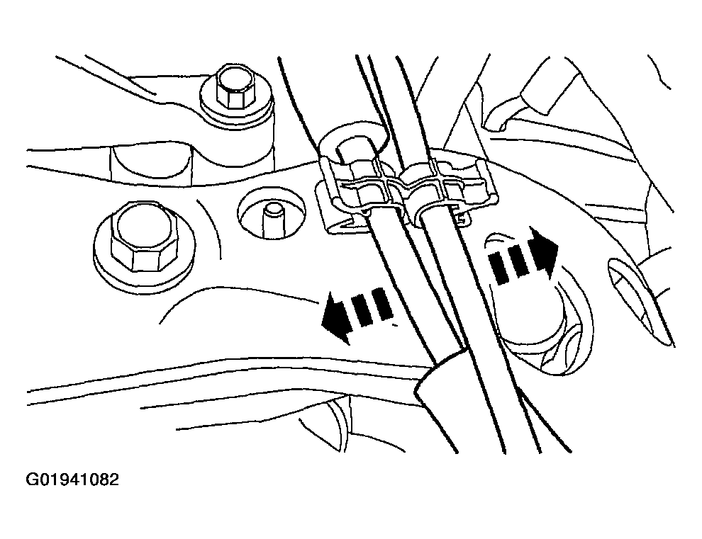
  29. Remove the cables from the crash bracket.
    Fig 20: Removing Cables From Crash Bracket
    G01941082Courtesy of FORD MOTOR CO.
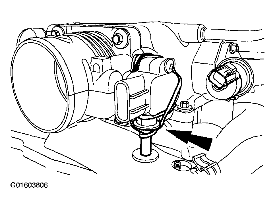
  30. Remove the crash bracket bolt and prevent the bolt from contacting the cylinder head with a rubber band or tie strap.
    Fig 21: Removing Crash Bracket Bolt
    G01603806Courtesy of FORD MOTOR CO.
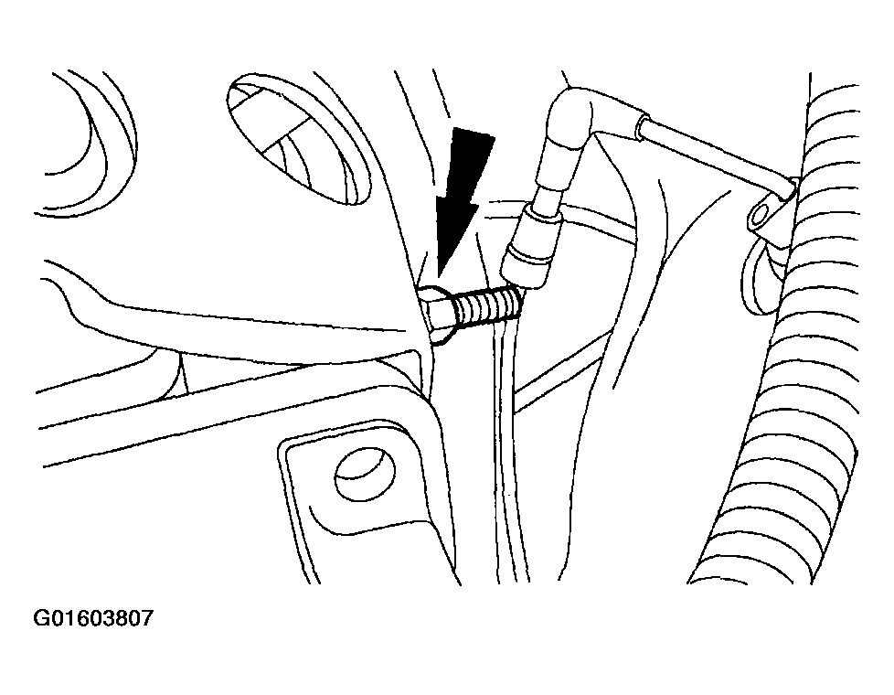
  31. Remove the stud.
    Fig 22: Removing Crash Bracket Stud
    G01603807Courtesy of FORD MOTOR CO.
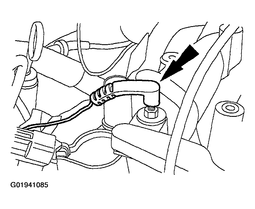
  32. Remove the ground connector from the RH rear stud.
    Fig 23: Identifying Ground Connector
    G01941085Courtesy of FORD MOTOR CO.
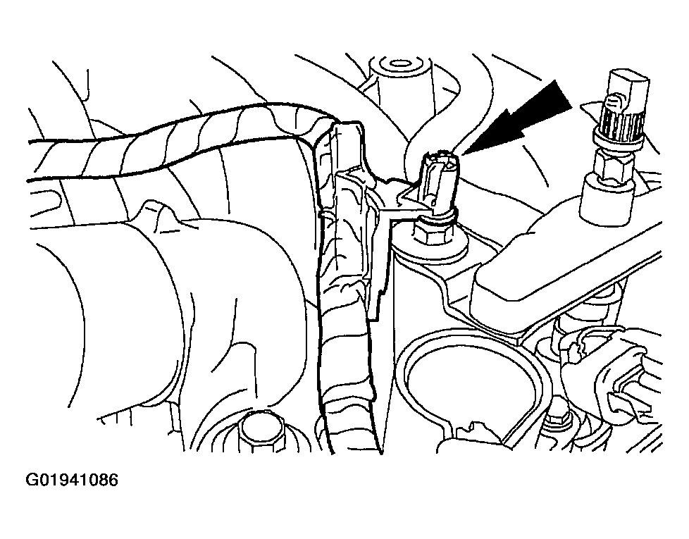
  33. Remove the generator harness pin-type retainer from the LH front stud.
    Fig 24: Identifying LH Front Stud Generator Harness Pin-Type Retainer
    G01941086Courtesy of FORD MOTOR CO.
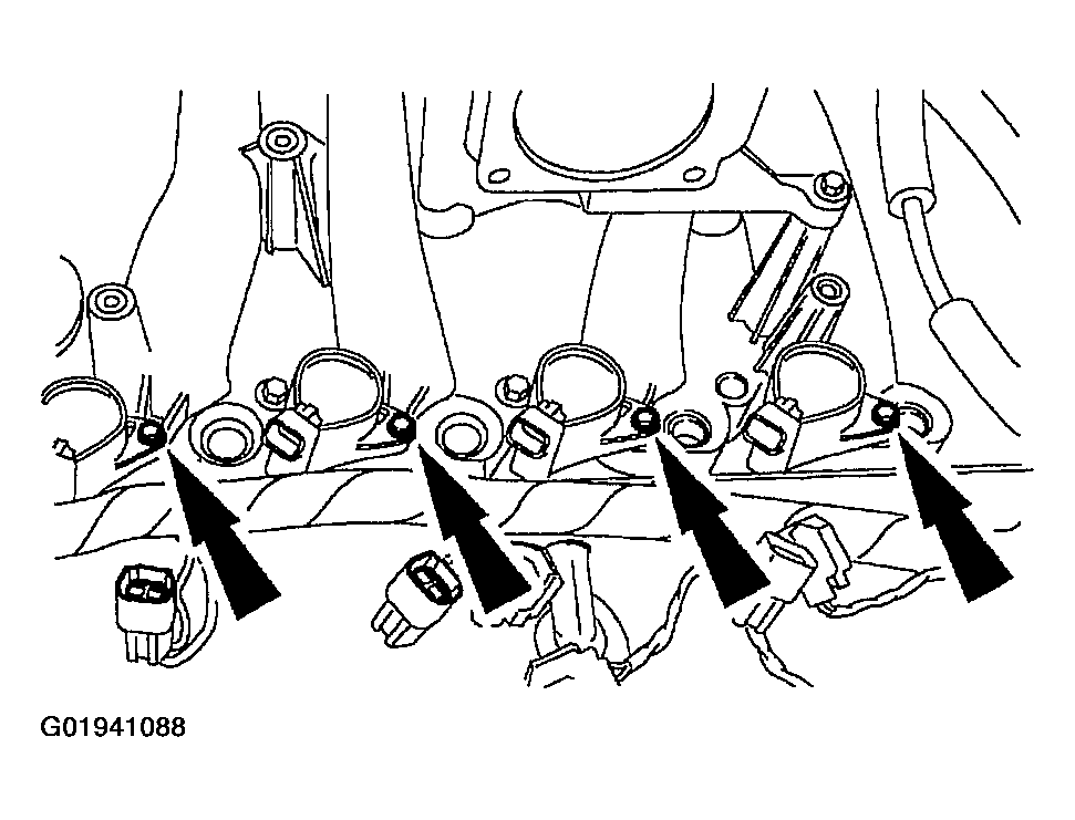
  34. Remove the eight bolts and the eight ignition coils.
    Fig 25: Identifying Ignition Coil Bolts
    G01941088Courtesy of FORD MOTOR CO.
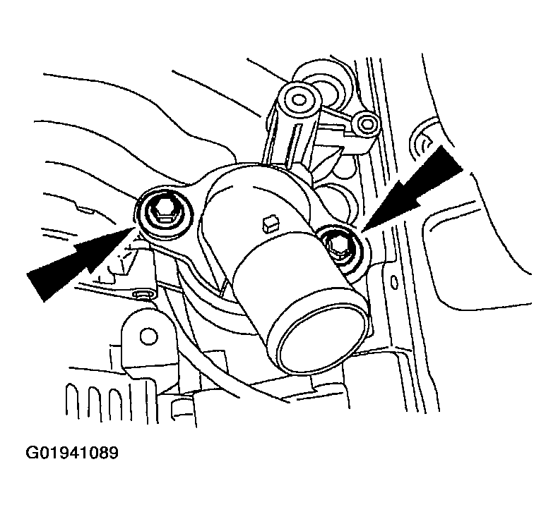
  35. Remove the bolts and the water outlet adapter.
    Fig 26: Identifying Water Outlet Adapter Bolts
    G01941089Courtesy of FORD MOTOR CO.
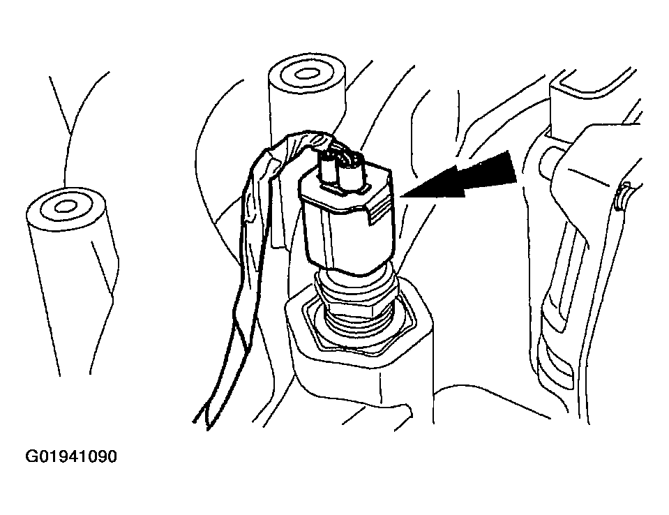
  36. Disconnect the cooling sensor electrical connector.
    Fig 27: Identifying Cooling Sensor Electrical Connector
    G01941090Courtesy of FORD MOTOR CO.
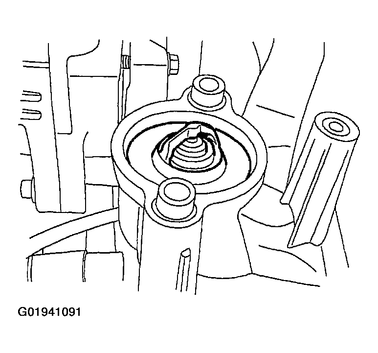
  37. Remove the water thermostat.
    Fig 28: Identifying Water Thermostat
    G01941091Courtesy of FORD MOTOR CO.
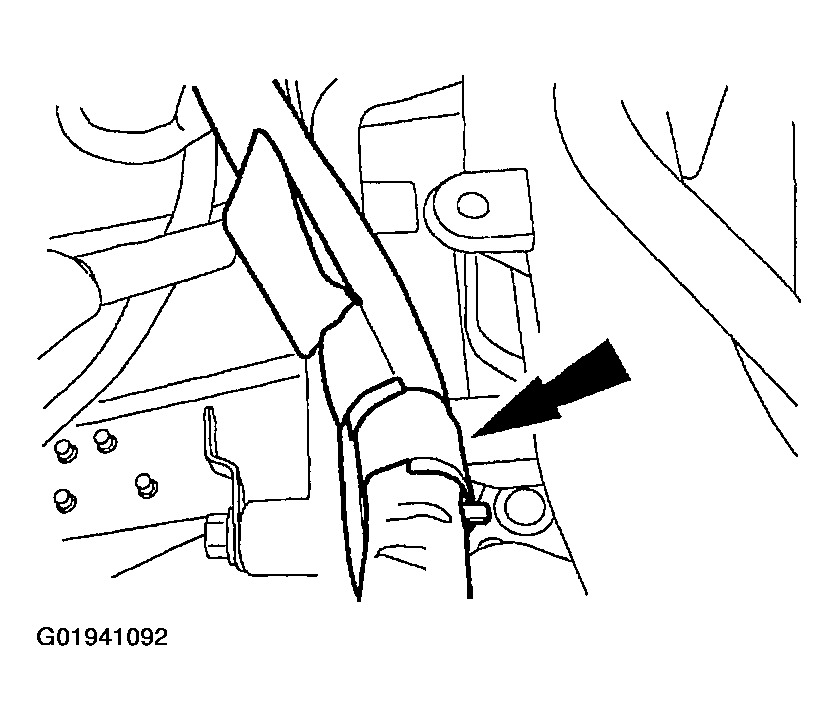
  38. Remove the fuel charging wiring position retainer from the rear of the intake manifold.
    Fig 29: Identifying Fuel Charging Wiring Position Retainer
    G01941092Courtesy of FORD MOTOR CO.
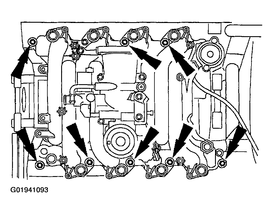
  39. Remove the bolts and the intake manifold.
    Fig 30: Identifying Intake Manifold Bolts
    G01941093Courtesy of FORD MOTOR CO.
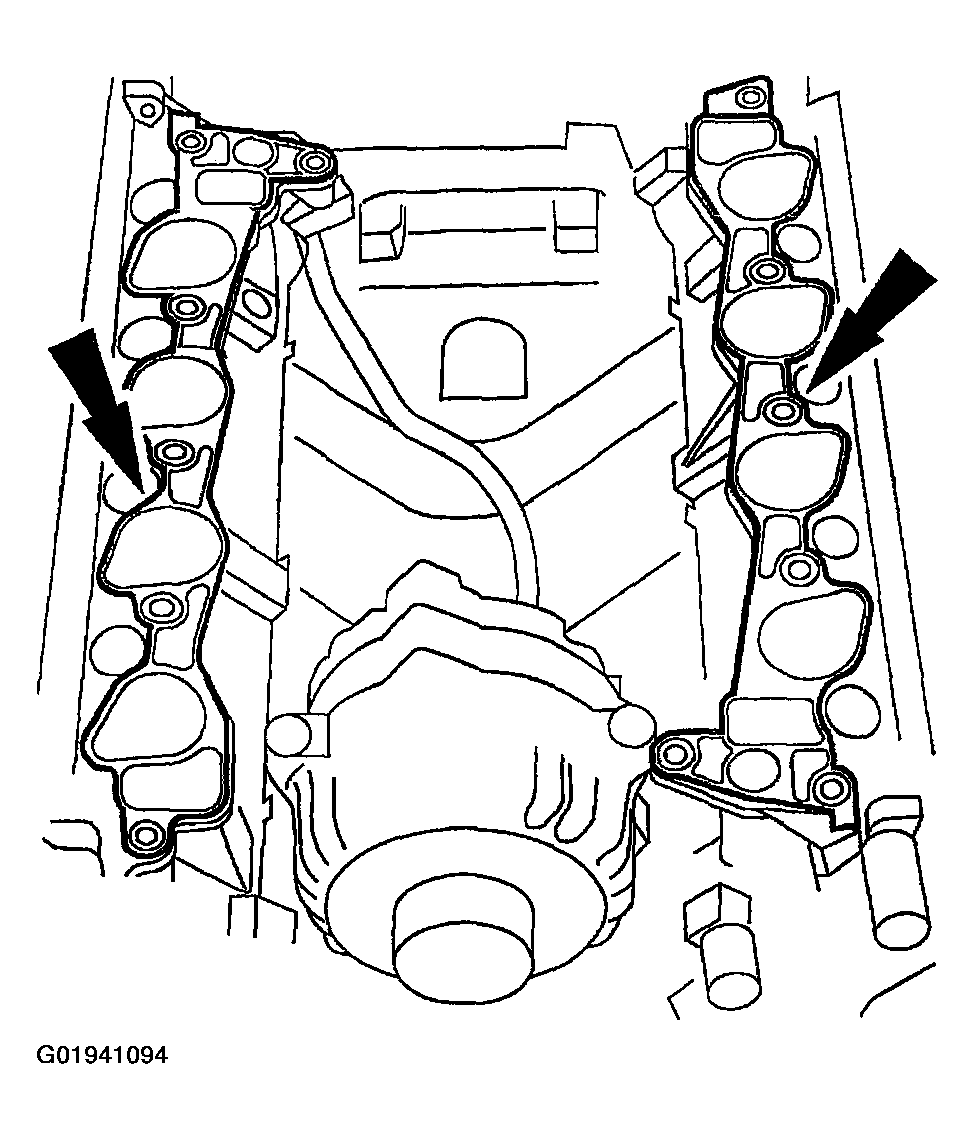
  40. Remove the intake manifold gaskets.
    Fig 31: Identifying Intake Manifold Gaskets
    G01941094Courtesy of FORD MOTOR CO.
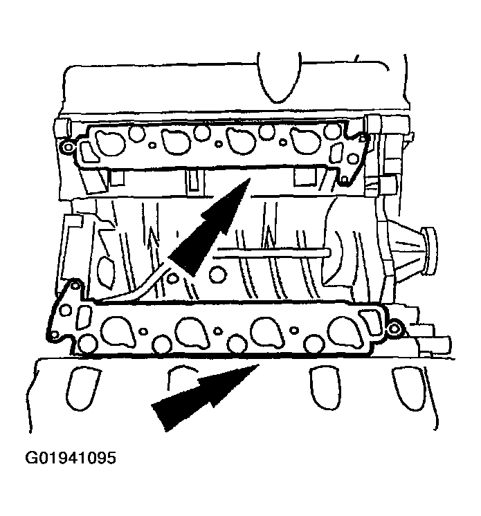
  41. Clean the sealing surfaces.
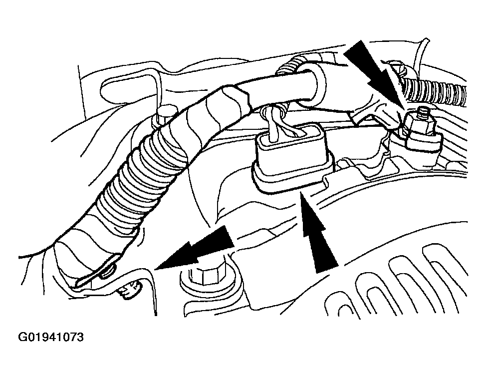
    Fig 32: Identifying Intake Manifold Sealing Surfaces
    G01941095Courtesy of FORD MOTOR CO.