Intake Manifold - Natural Gas Engines: Installation
- Install new intake manifold gaskets.
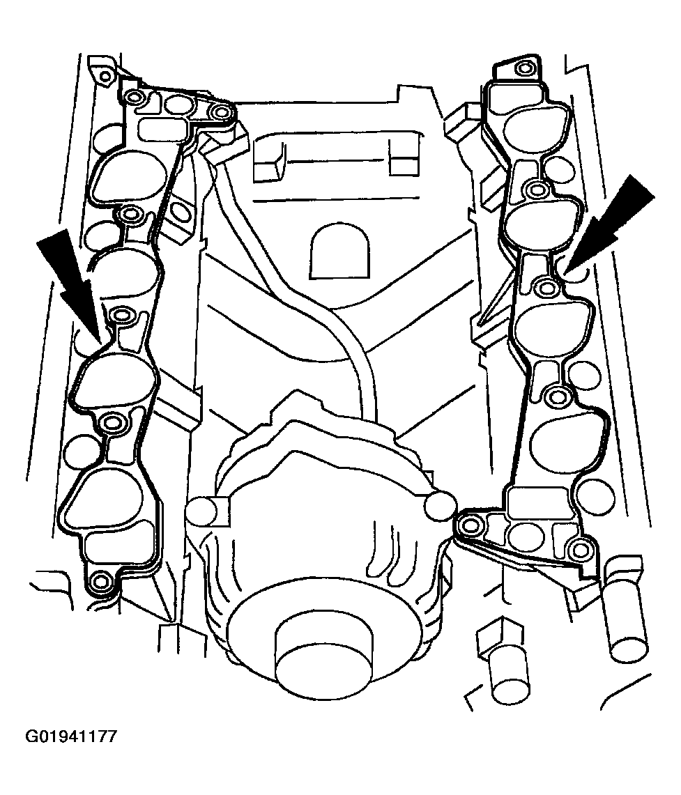 Courtesy of FORD MOTOR CO.
- Install the intake manifold.
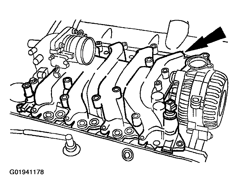 Courtesy of FORD MOTOR CO.
- Install the bolts and tighten in the sequence shown in illustration.
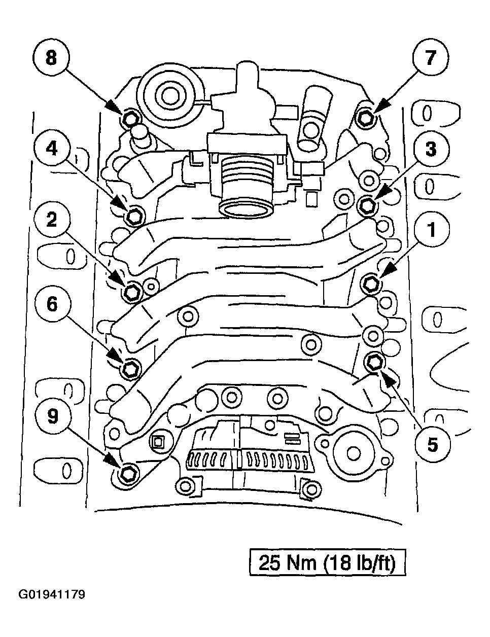 Courtesy of FORD MOTOR CO.
- Install the water thermostat and a new O-ring.
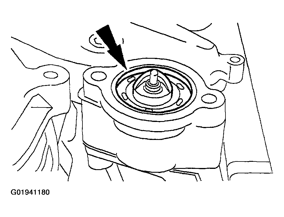 Courtesy of FORD MOTOR CO.
- Install the water outlet adapter and tighten the bolts.
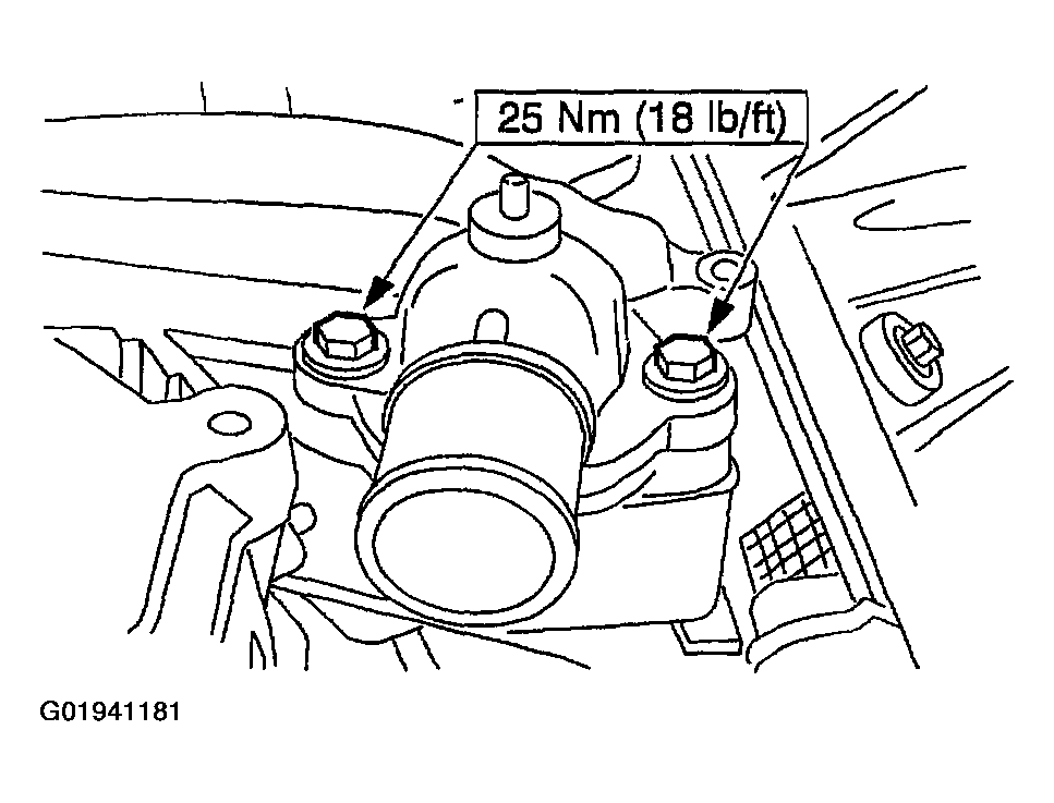 Courtesy of FORD MOTOR CO.
- Install the generator support bracket and tighten the bolts.
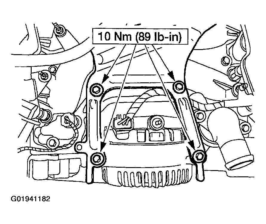 Courtesy of FORD MOTOR CO.
- Install the eight ignition coils and tighten the bolts.
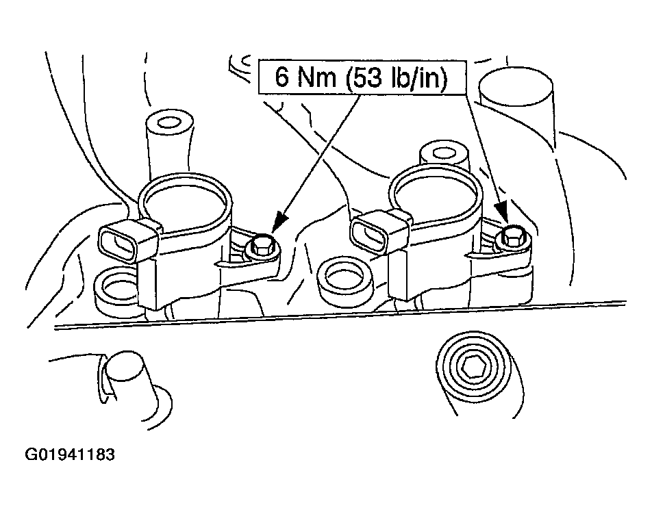 Courtesy of FORD MOTOR CO.
- Connect the upper radiator hose to the water outlet adapter.
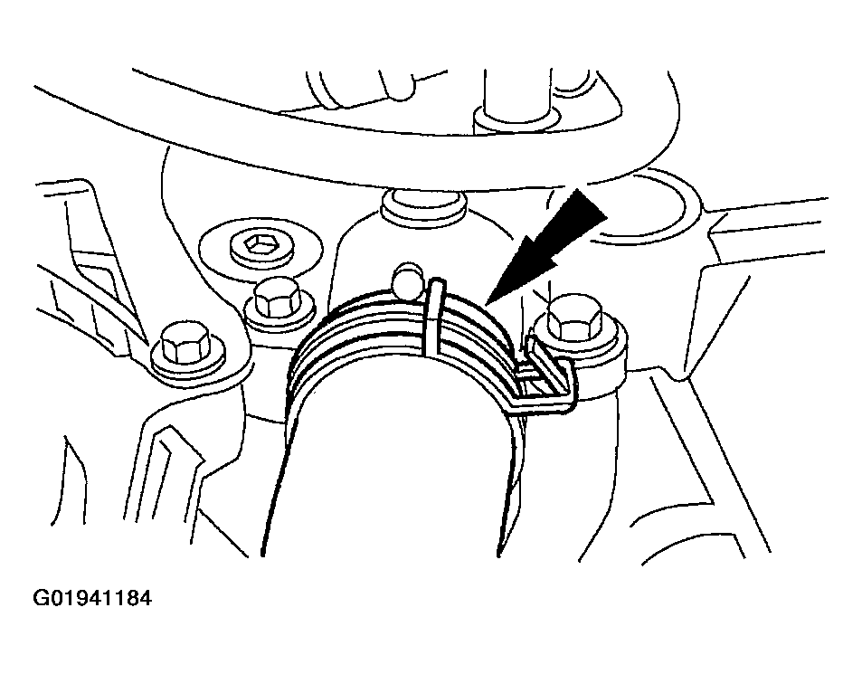 Courtesy of FORD MOTOR CO.
- Connect the heater water hose to the intake manifold.
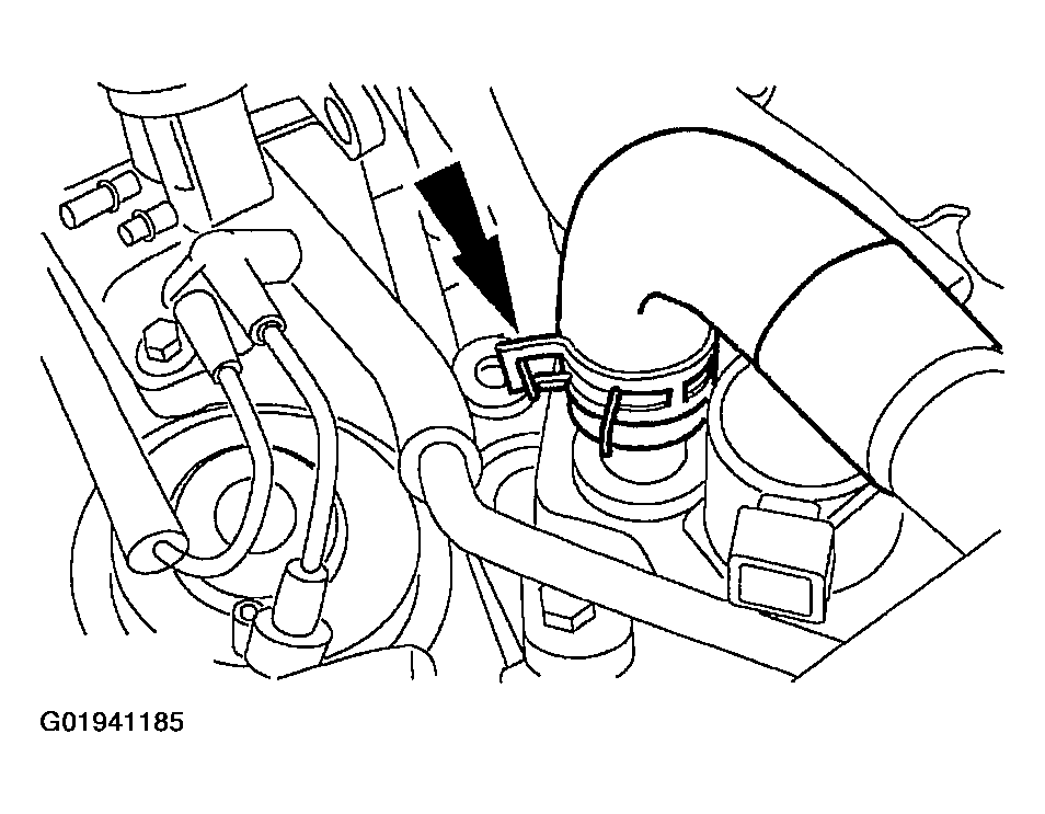 Courtesy of FORD MOTOR CO.
- Install the fuel injectors and the fuel injection supply manifold as an assembly.
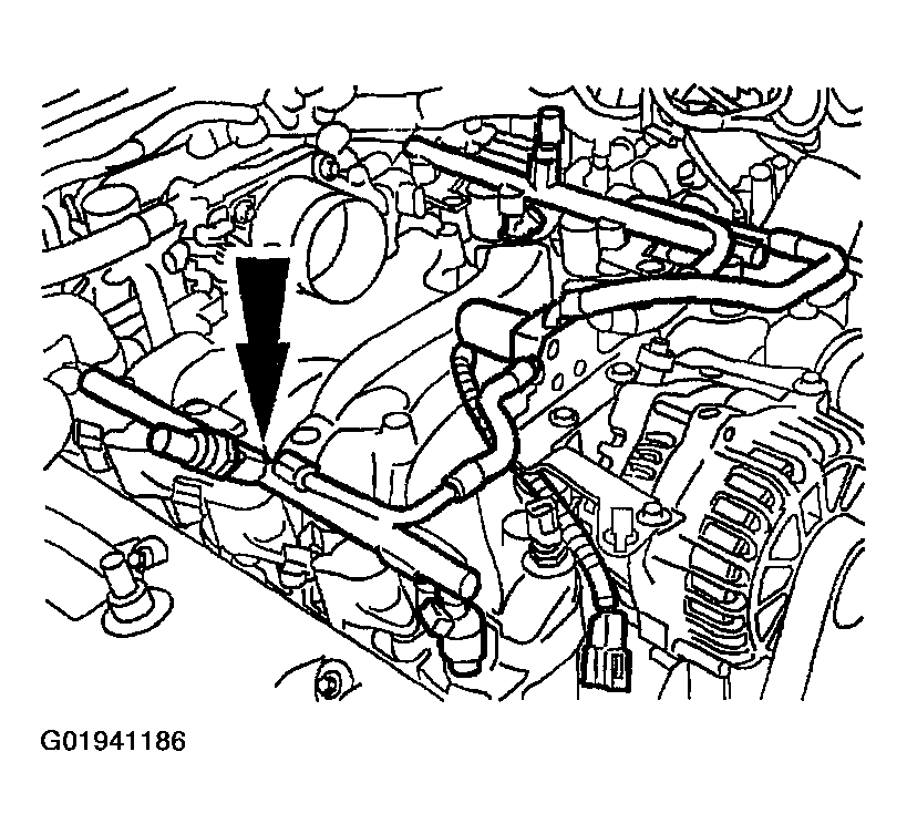 Courtesy of FORD MOTOR CO.
- Install the four bolts.
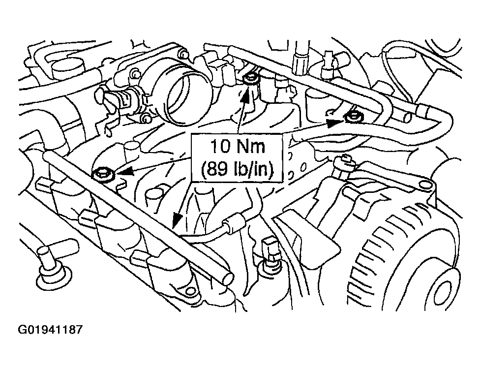 Courtesy of FORD MOTOR CO.
- Install the bolts in the isolation valve and tighten.
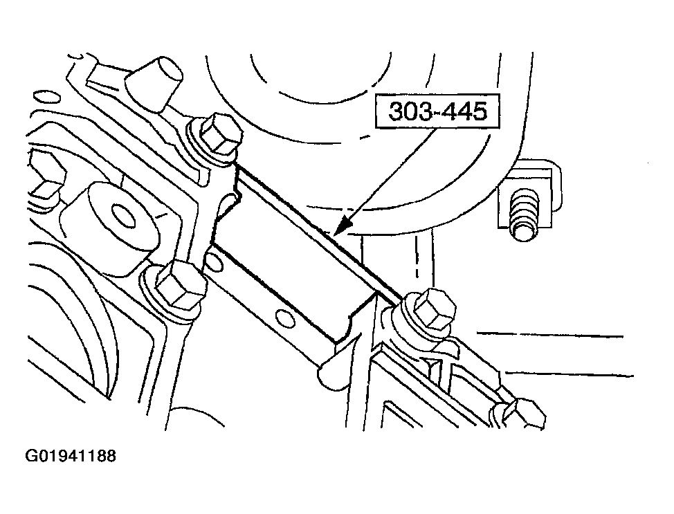 Courtesy of FORD MOTOR CO.
- Connect the EGR tube to the EGR valve.
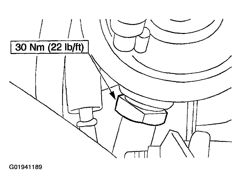 Courtesy of FORD MOTOR CO.
- Connect the vacuum hoses to the EGR vacuum regulator solenoid.
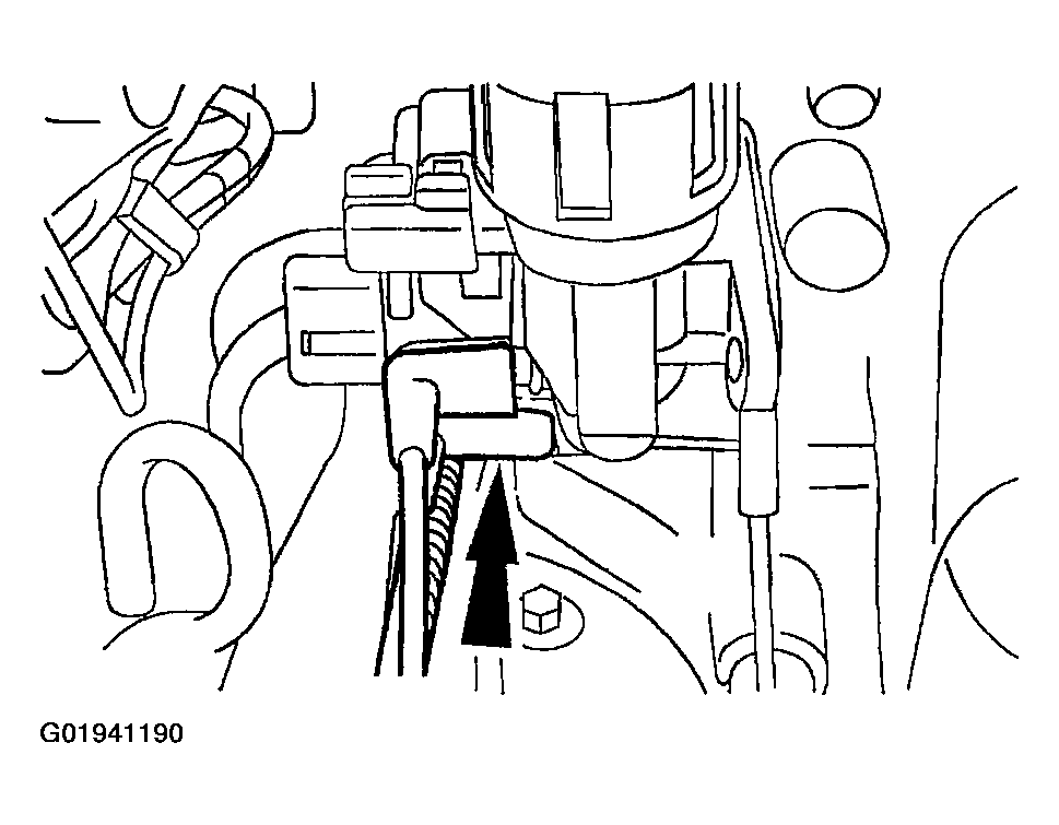 Courtesy of FORD MOTOR CO.
- Connect the vacuum hoses to the throttle body adapter.
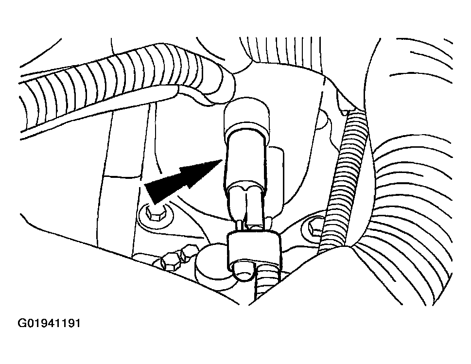 Courtesy of FORD MOTOR CO.
- Install the crankcase ventilation tube and connect at two locations.
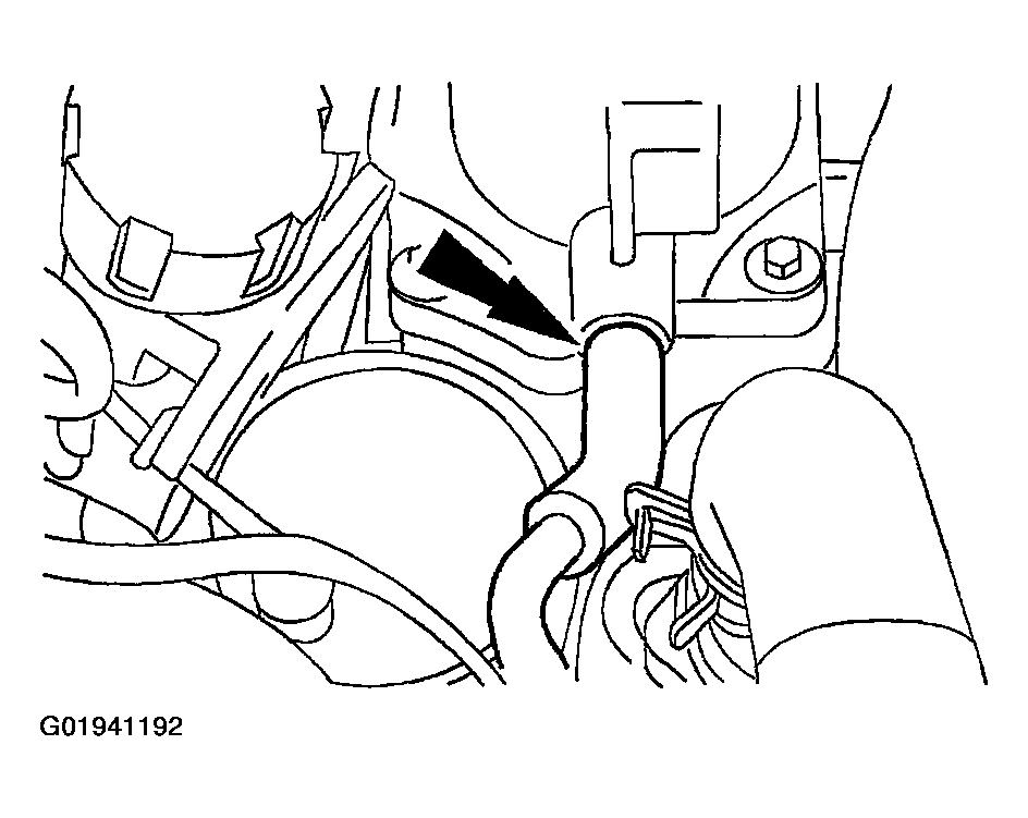 Courtesy of FORD MOTOR CO.
- Connect the main chassis vacuum supply hose to the throttle body adapter.
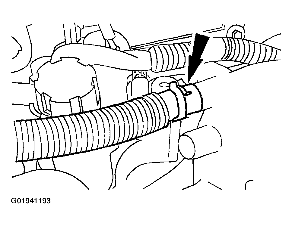 Courtesy of FORD MOTOR CO.
- Connect the vacuum hose to the EGR valve.
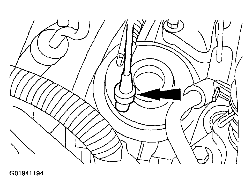 Courtesy of FORD MOTOR CO.
- Connect the hoses to the differential pressure feedback exhaust gas recirculation (EGR) system.
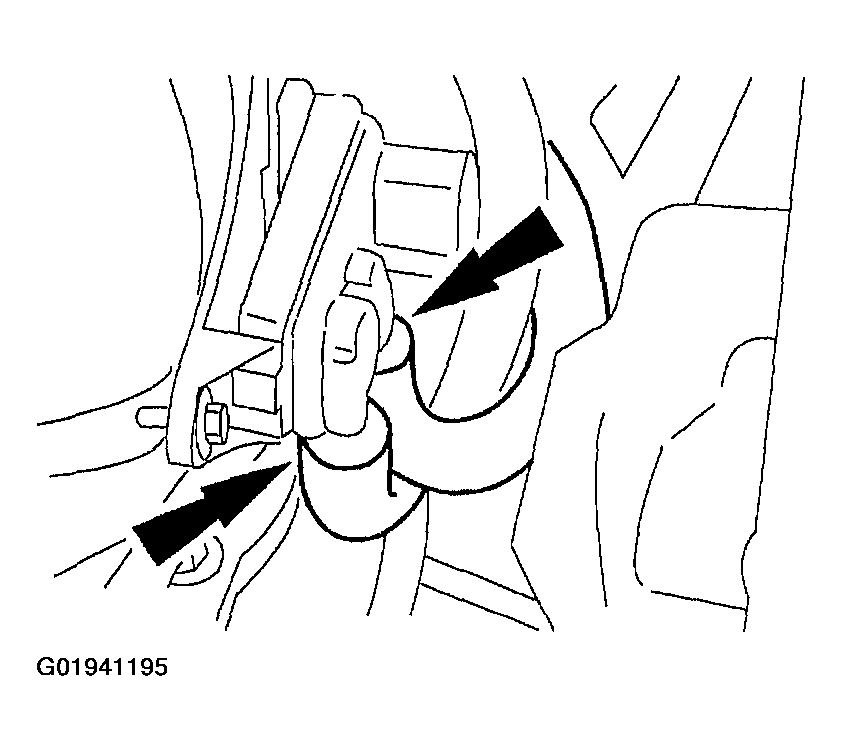 Courtesy of FORD MOTOR CO.
- Connect the fuel lines. For additional information, refer to FUEL SYSTEMS
.
- Position the fuel charging wiring and install the bolts.
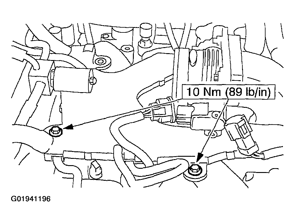 Courtesy of FORD MOTOR CO.
- Position the cables and the bracket and install the bolts.
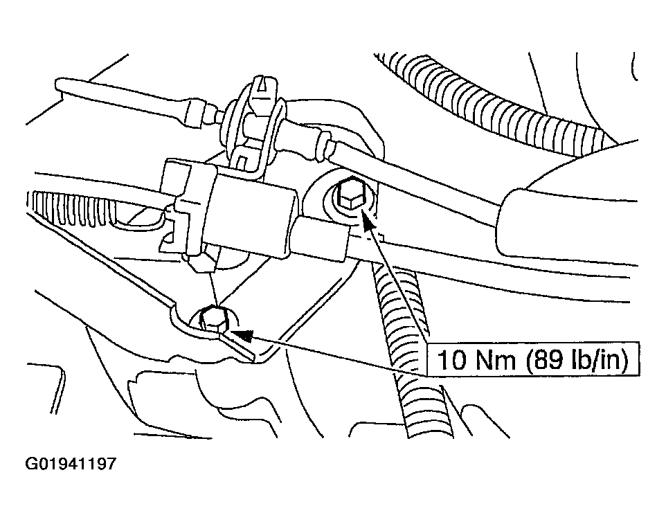 Courtesy of FORD MOTOR CO.
- Connect the throttle cable and the speed control actuator cable to the throttle body.
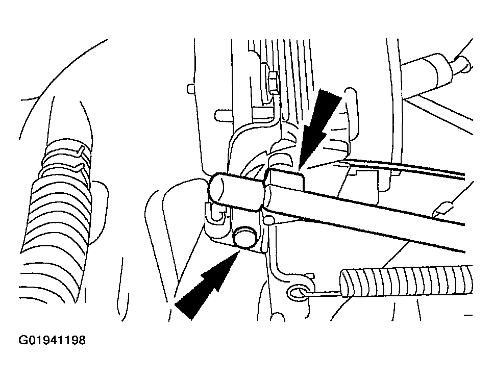 Courtesy of FORD MOTOR CO.
- Connect the fuel charging wiring to the idle air control valve.
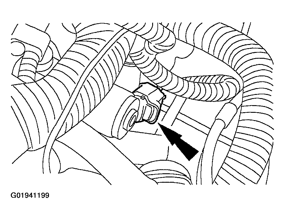 Courtesy of FORD MOTOR CO.
- Connect the differential pressure feedback EGR system electrical connector.
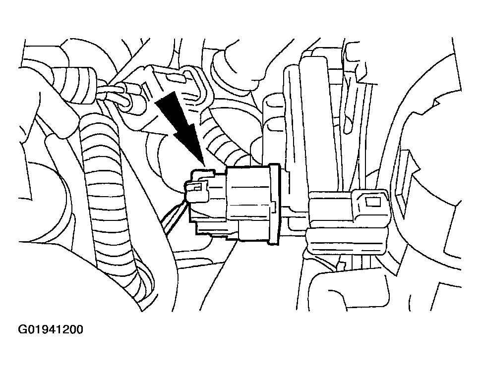 Courtesy of FORD MOTOR CO.
- Connect the fuel charging wiring to the EGR vacuum regulator solenoid.
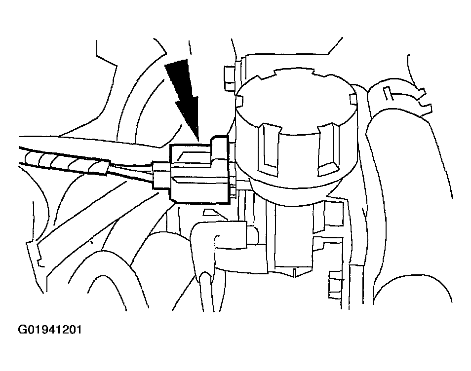 Courtesy of FORD MOTOR CO.
- Connect the fuel charging wiring to the radio ignition interference capacitor.
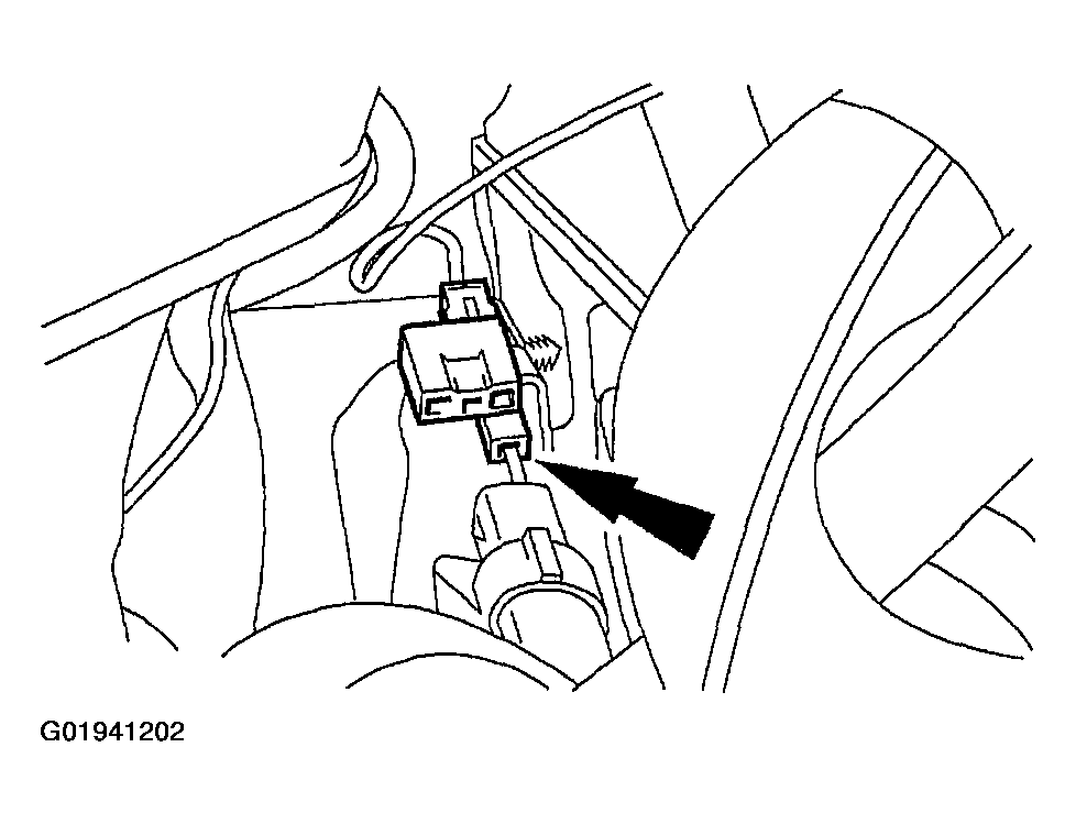 Courtesy of FORD MOTOR CO.
- Connect the fuel charging wiring electrical connector to the throttle position sensor.
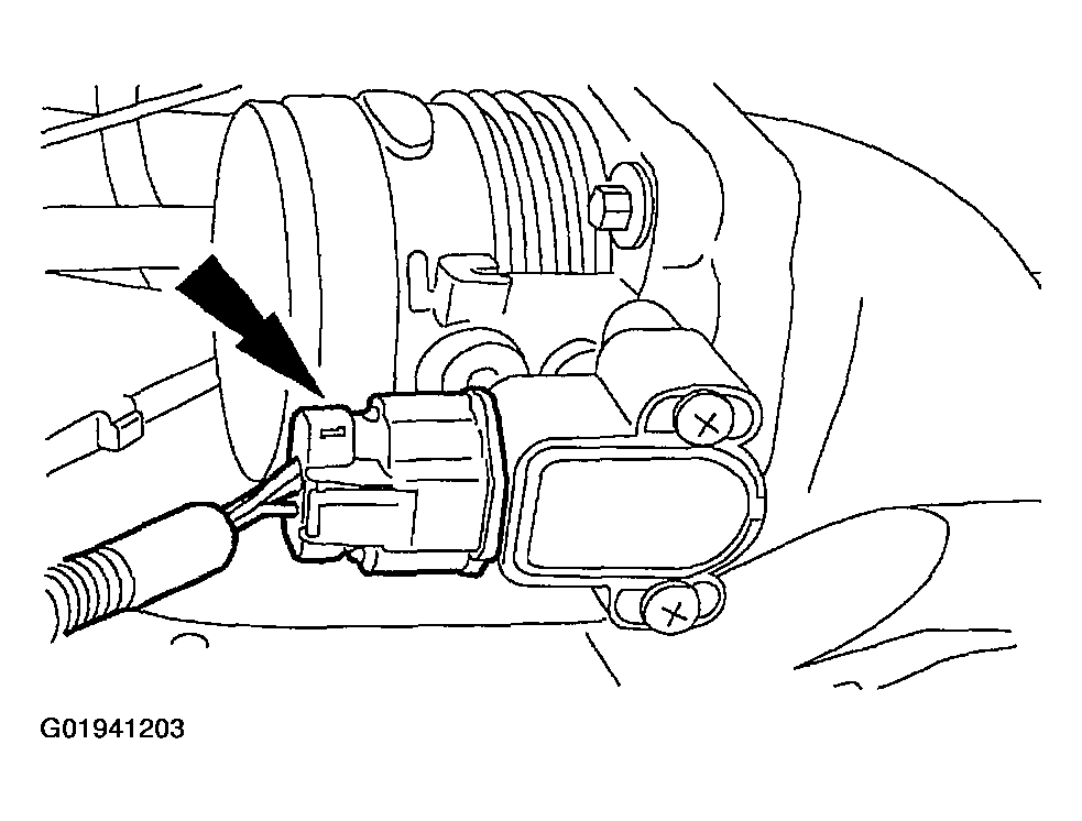 Courtesy of FORD MOTOR CO.
- Connect the fuel charging wiring electrical connector to the generator.
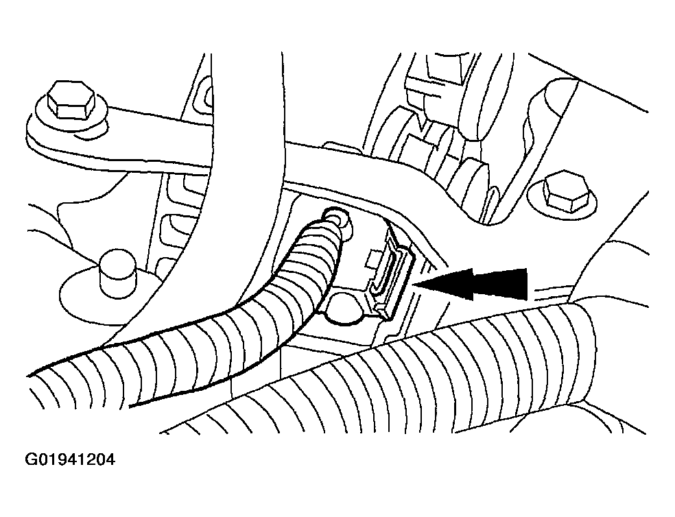 Courtesy of FORD MOTOR CO.
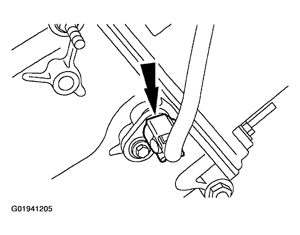
- Connect the fuel charging wiring electrical connector to the camshaft position sensor.
 Courtesy of FORD MOTOR CO.
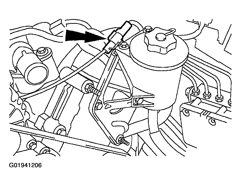
- Connect the fuel charging wiring electrical connector to the cylinder head temperature sensor jumper.
 Courtesy of FORD MOTOR CO.
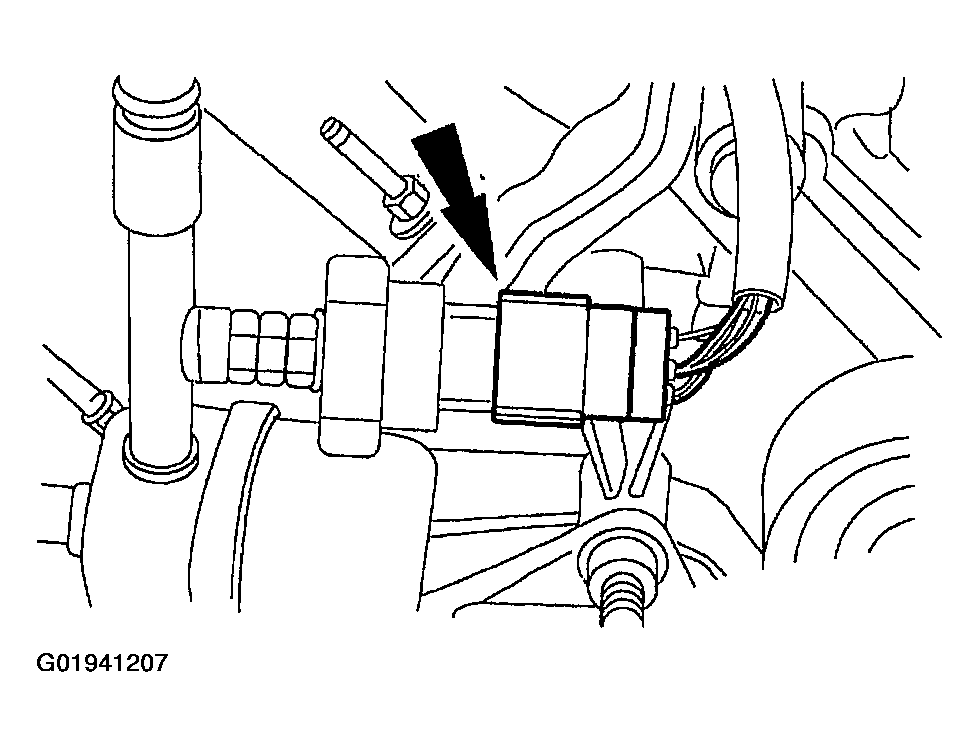
- Connect the fuel charging wiring electrical connector to the A/C pressure transducer.
 Courtesy of FORD MOTOR CO.
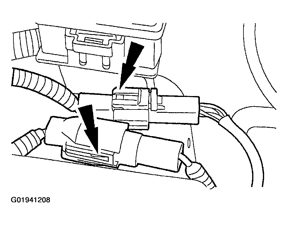
- Connect the fuel charging wiring electrical connectors at the inner fender splash shield.
 Courtesy of FORD MOTOR CO.
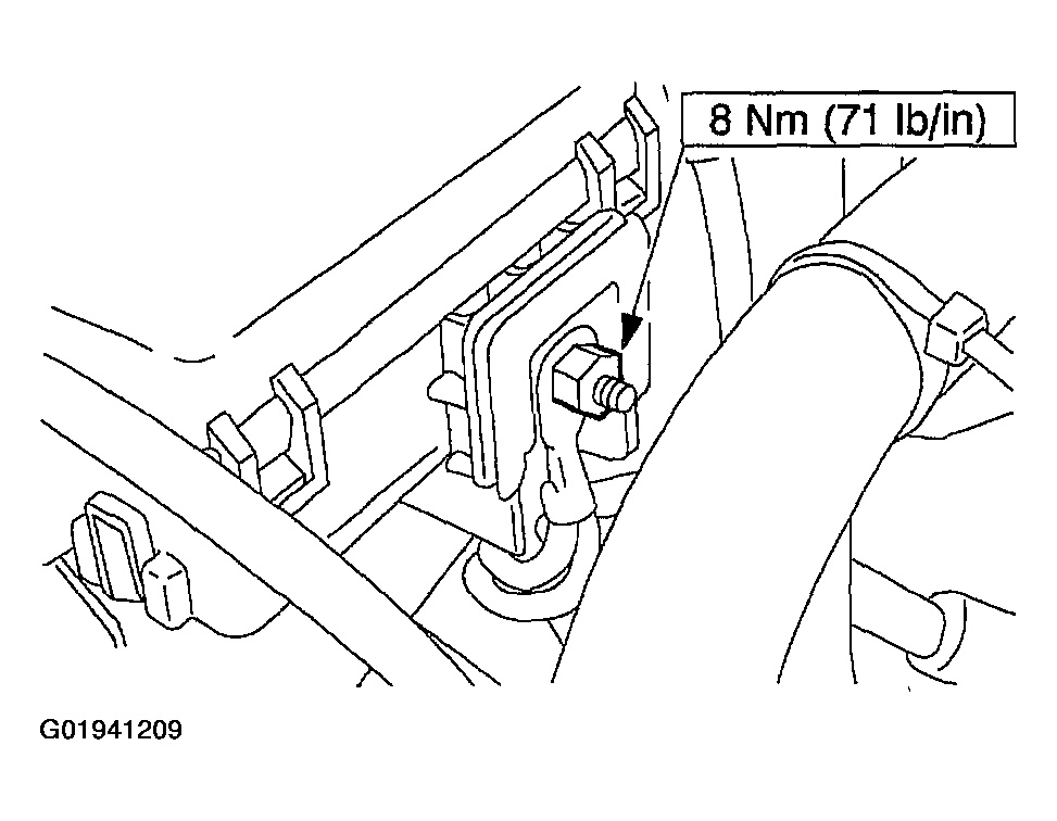
- Reposition the wiring on the stud and tighten the nut.
 Courtesy of FORD MOTOR CO.
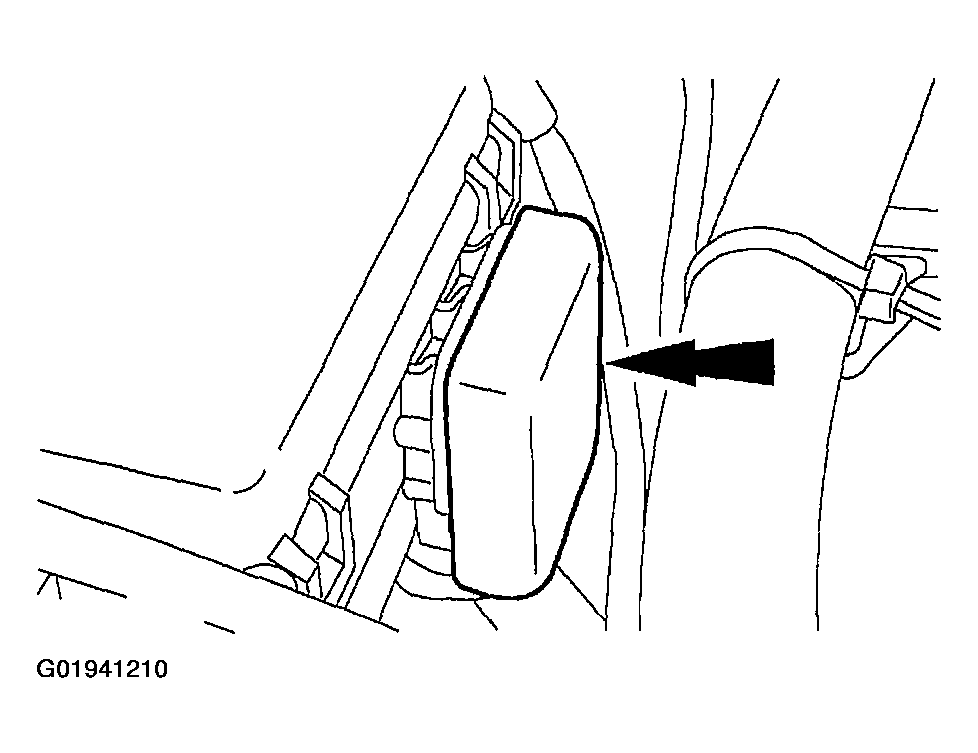
- Install the power distribution box access cover.
 Courtesy of FORD MOTOR CO.
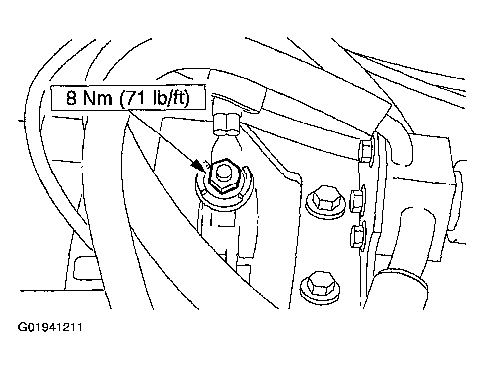
- Connect the generator battery cable and tighten the nut.
 Courtesy of FORD MOTOR CO.
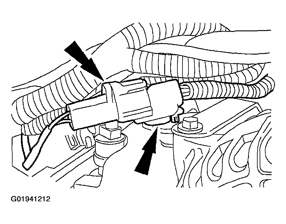
- Connect the isolation valve jumper to the fuel charging wiring electrical connector.
 Courtesy of FORD MOTOR CO.
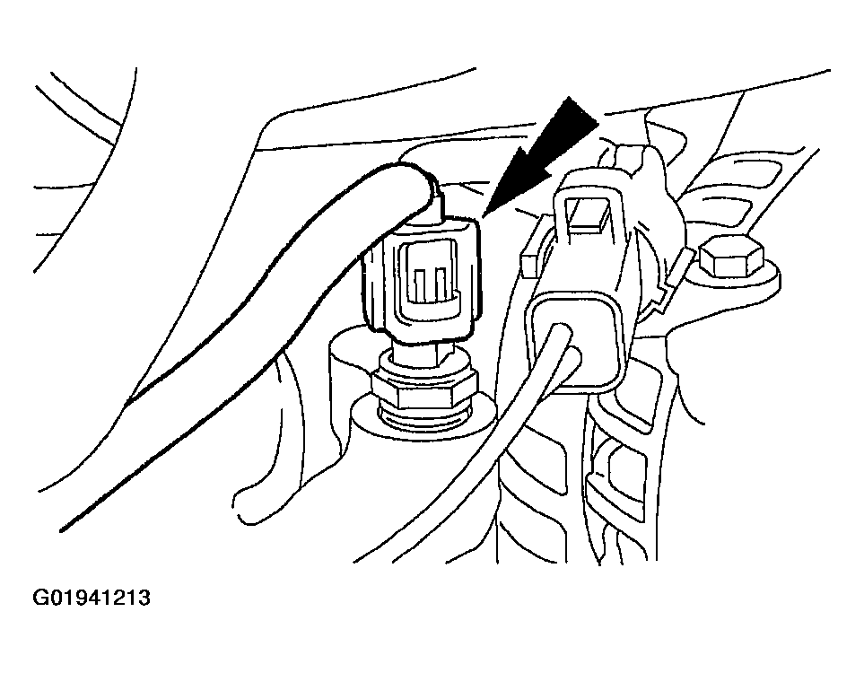
- Connect the fuel charging wiring electrical connector to the engine coolant temperature sensor.
 Courtesy of FORD MOTOR CO.
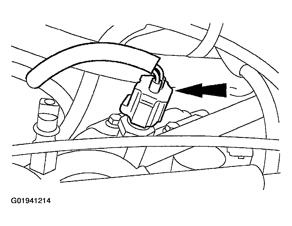
- Connect the fuel charging wiring electrical connector to the fuel temperature sensor.
 Courtesy of FORD MOTOR CO.
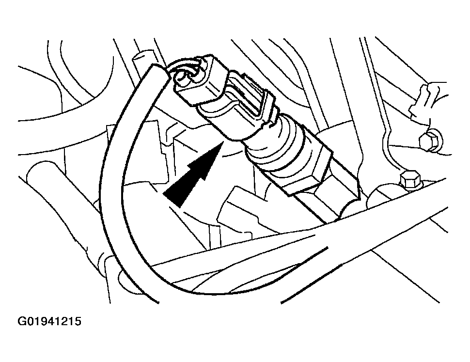
- Connect the fuel charging wiring electrical connector to the fuel pressure sensor.
 Courtesy of FORD MOTOR CO.
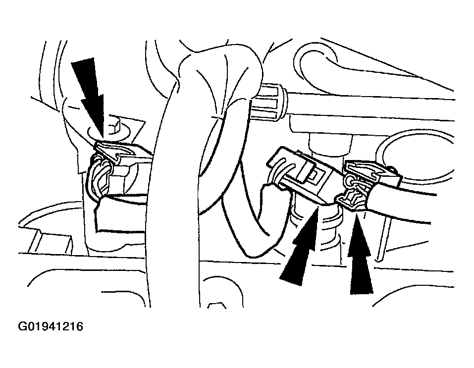
- Connect the fuel charging wiring electrical connectors to the eight ignition coils and the eight fuel injectors.
 Courtesy of FORD MOTOR CO.
- Install the wiper arm and pivot shaft. For additional information, refer to MOUNTING ARM AND PIVOT SHAFT
.
- Install the air cleaner outlet tube.