Cylinder Head RH: Installation
- Make sure the sealing surface and bolt holes are clean and dry.
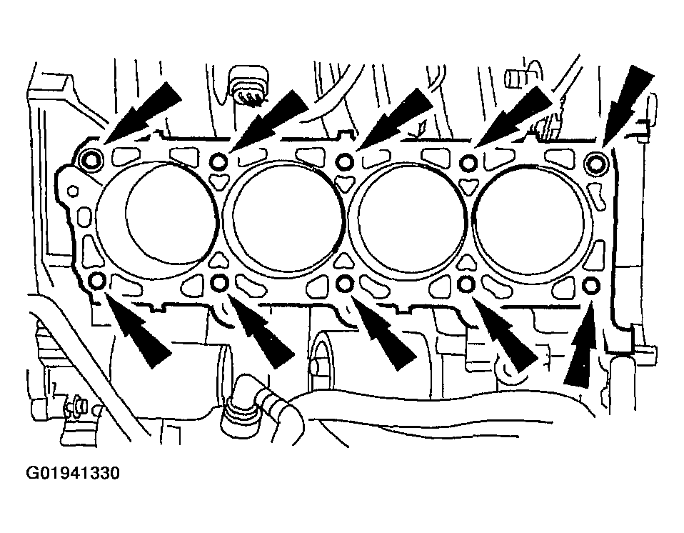 Courtesy of FORD MOTOR CO.
- Install a new gasket.
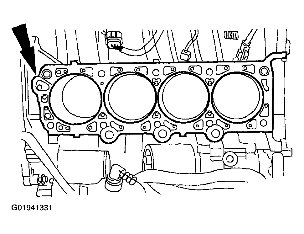 Courtesy of FORD MOTOR CO.
- Install the RH cylinder head.
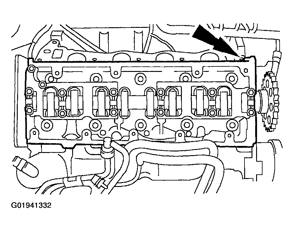 Courtesy of FORD MOTOR CO.
- Install the bolts and tighten in sequence in six steps:
- Step 1: Tighten to 37-43 N.m (28-31 lb-ft).
- Step 2: Tighten an additional 85-95 degrees.
- Step 3: Loosen the bolts a minimum of one full turn (360 degrees).
- Step 4: Tighten to 37-43 N.m (28-31 lb-ft).
- Step 5: Tighten an additional 85-95 degrees.
- Step 6: Tighten an additional 85-95 degrees.
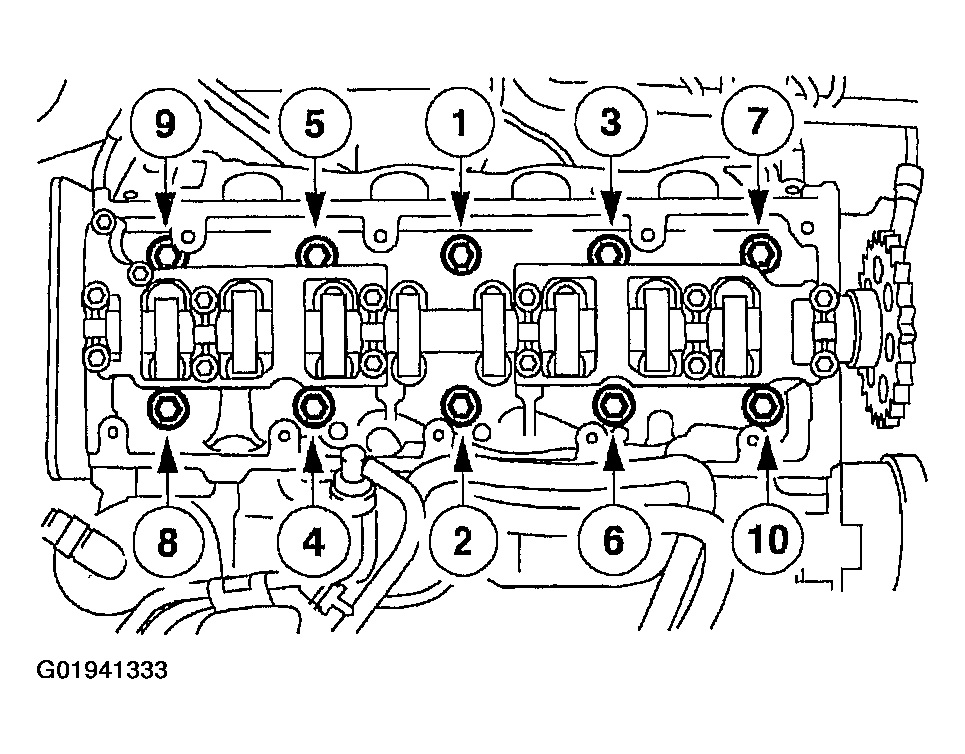 Courtesy of FORD MOTOR CO.
- Raise the vehicle.
- Install the exhaust to the exhaust manifolds nuts.
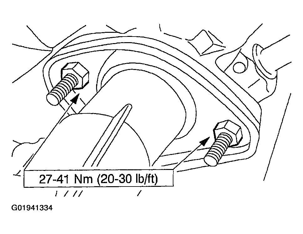 Courtesy of FORD MOTOR CO.
- Lower the vehicle.
- Install the bolt.
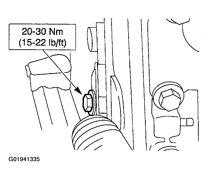 Courtesy of FORD MOTOR CO.
- Install the LH and RH timing chain guides.
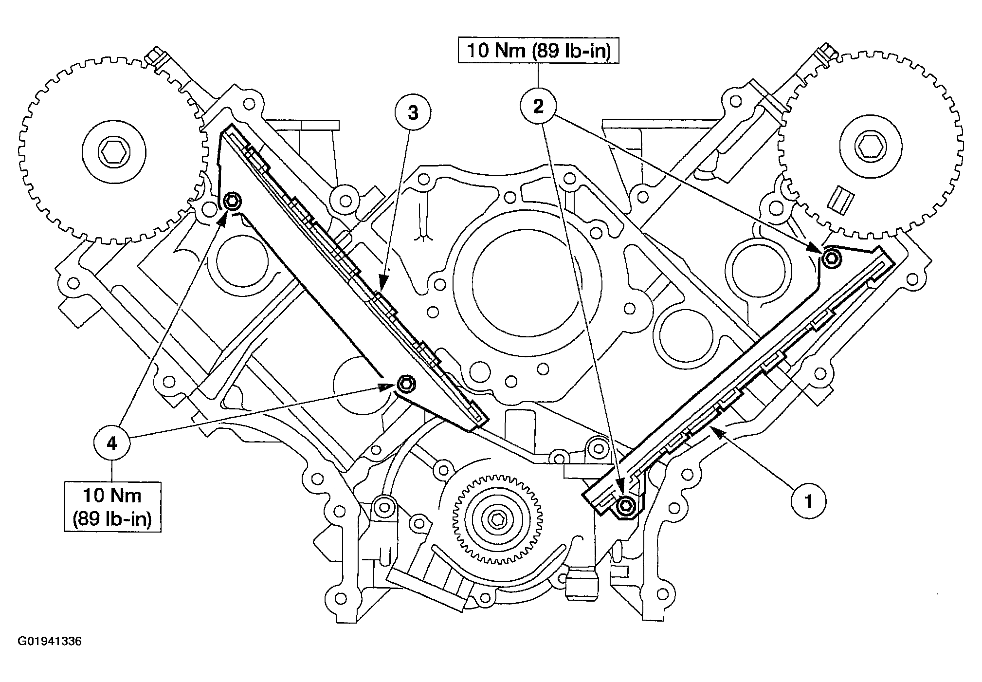 Courtesy of FORD MOTOR CO.
- Install the RH timing chain guide and tighten the bolts.
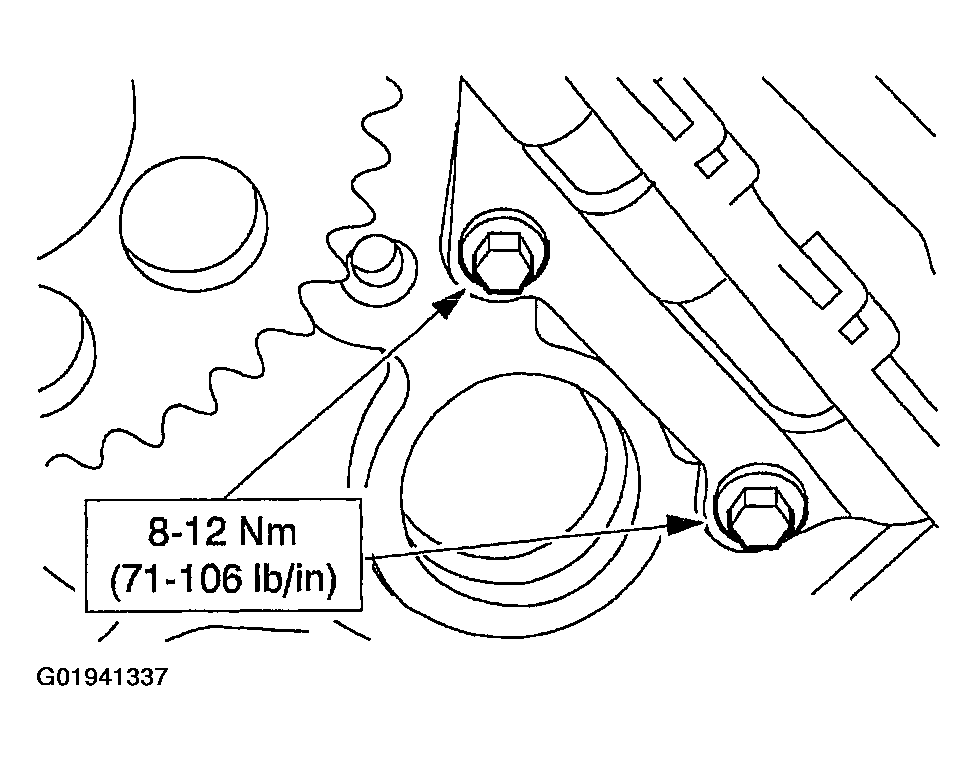 Courtesy of FORD MOTOR CO.
- Install the timing chain/belts. For additional information, refer to
TIMING DRIVE COMPONENTS .
- Install the water bypass tube.
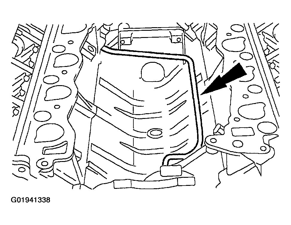 Courtesy of FORD MOTOR CO.
- Install the stud.
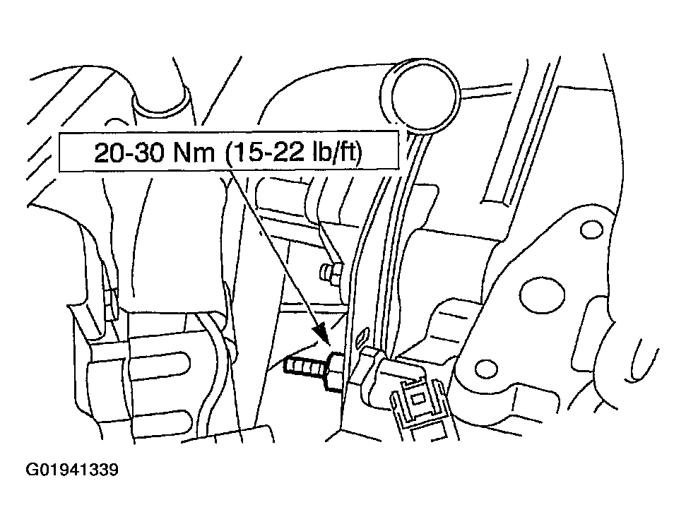 Courtesy of FORD MOTOR CO.
- Connect the differential pressure feedback EGR connector.
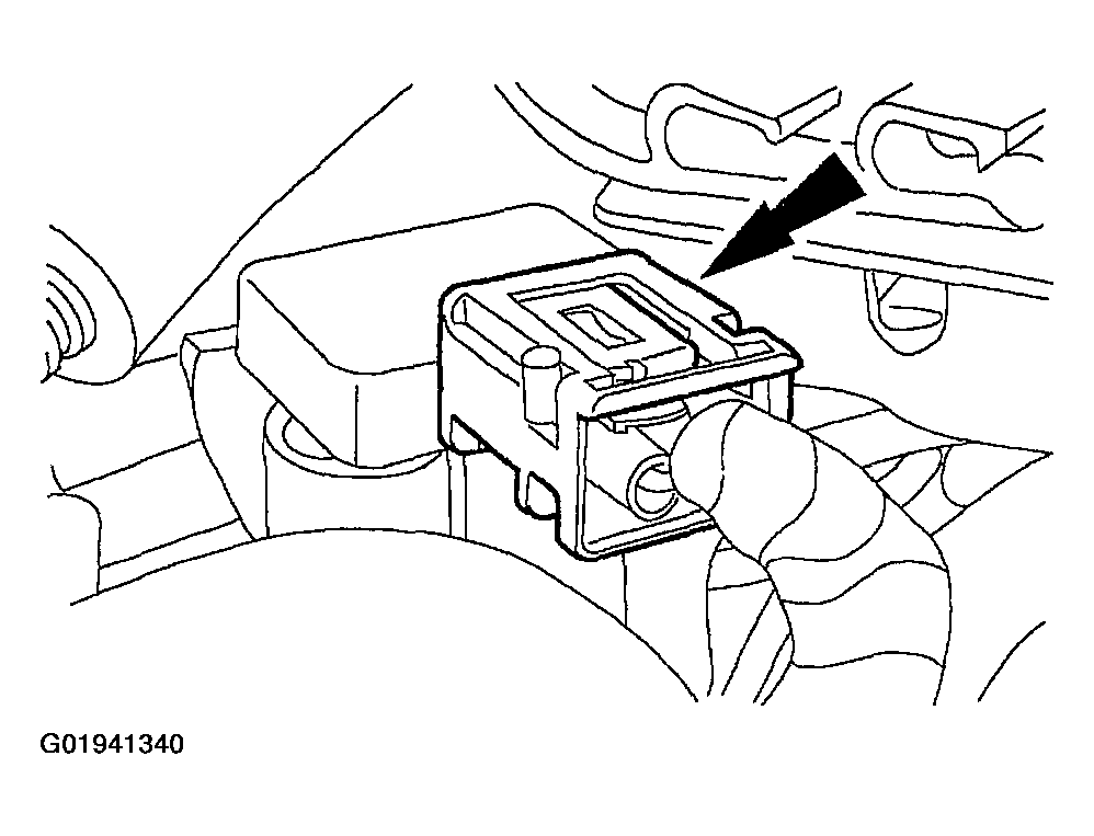 Courtesy of FORD MOTOR CO.
- Install the ground strap and tighten the nut.
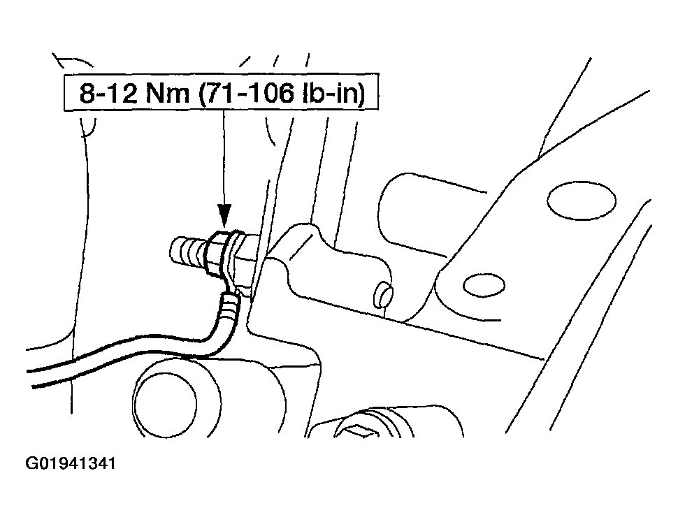 Courtesy of FORD MOTOR CO.
- Install the heater water hose (18472) and position the clamp.
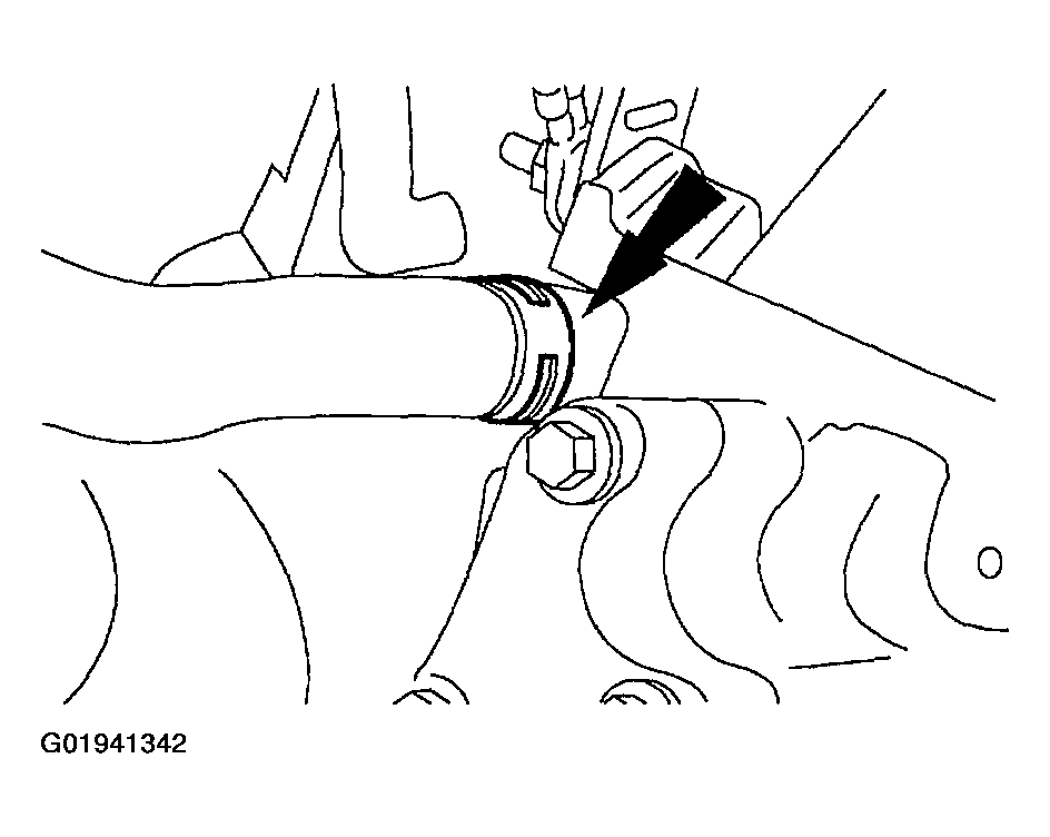 Courtesy of FORD MOTOR CO.
- Install the A/C evaporator housing. For additional information, refer to
EVAPORATOR CORE HOUSING
.
- Install the spark plugs.
- Install the engine front cover. For additional information, refer to
ENGINE FRONT COVER .
- Install the valve covers. For additional information, refer to VALVE COVER RH and
VALVE COVER LH
.
- Install the intake manifold. For additional information, refer to
INTAKE MANIFOLD - NATURAL GAS ENGINES or
INTAKE MANIFOLD - GASOLINE ENGINES
.
- Connect the battery ground cable.