Engine - 4.6L: Disassembly: Engine: Disassembly
All Engines
- Remove the accessory drive belt.
- Remove the bolt and the battery ground cable from the engine.
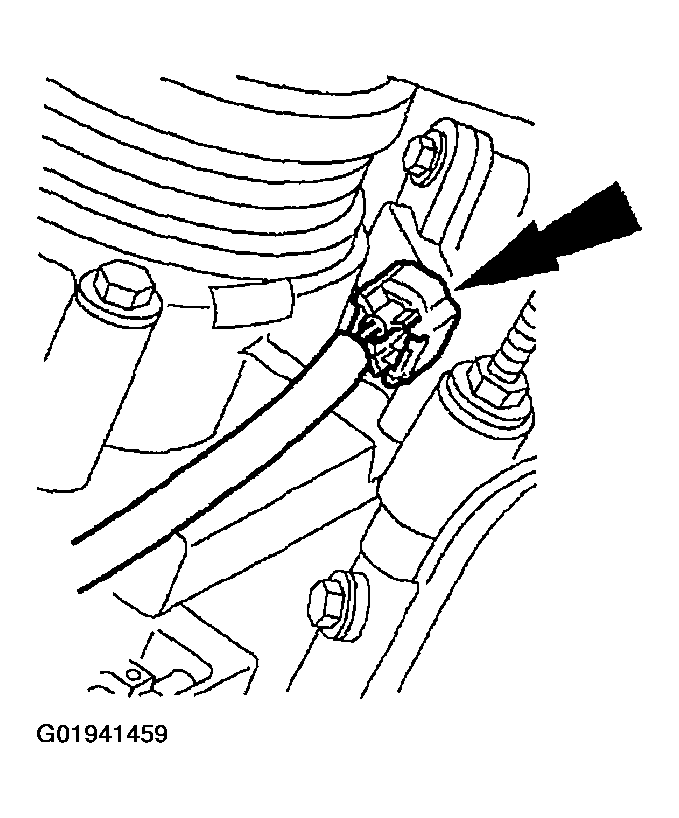
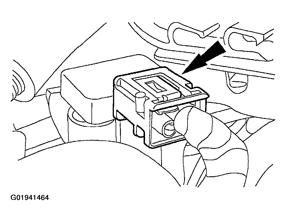
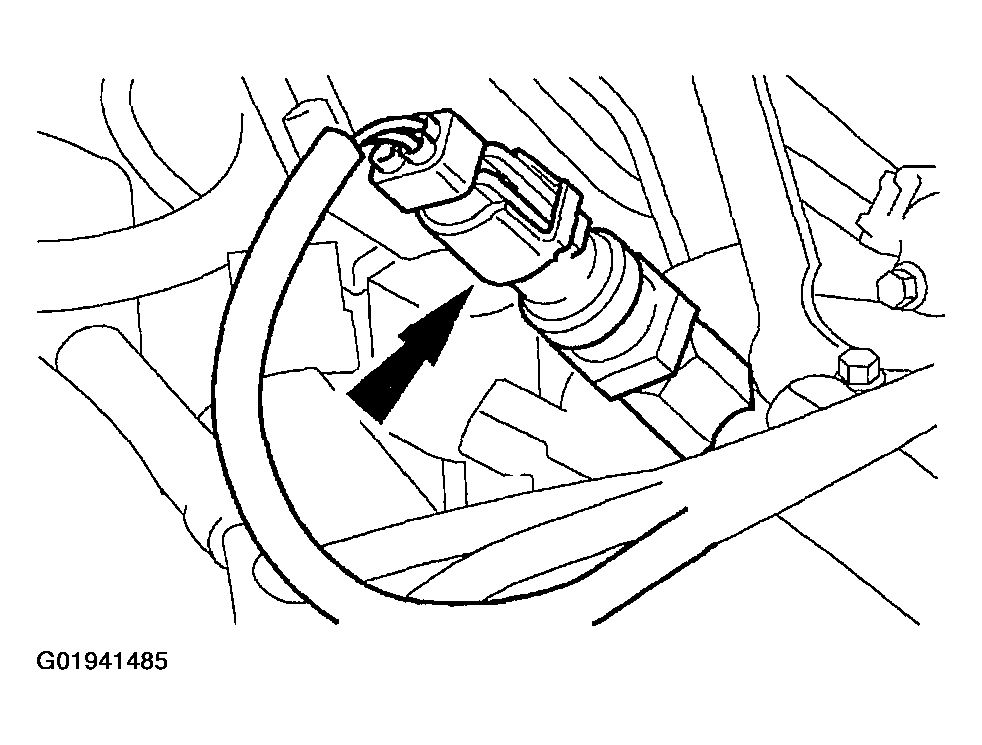
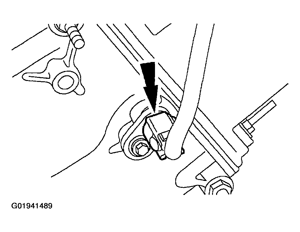
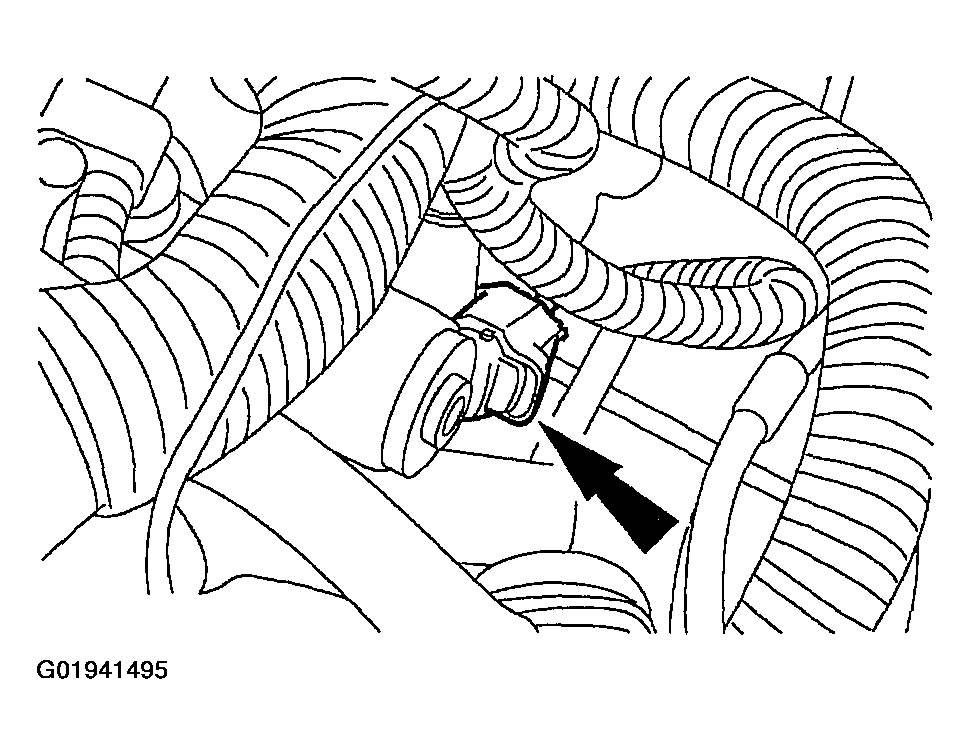
- Disconnect the fuel charging wiring electrical connector from the crankshaft position (CKP) sensor.
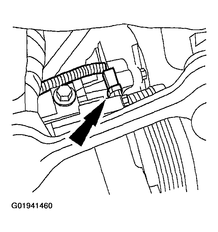
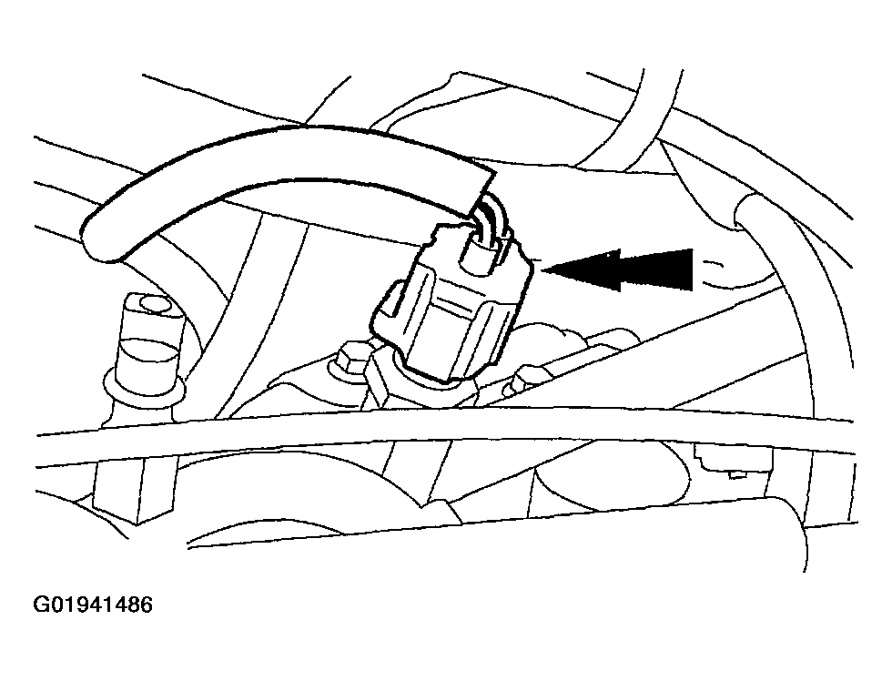
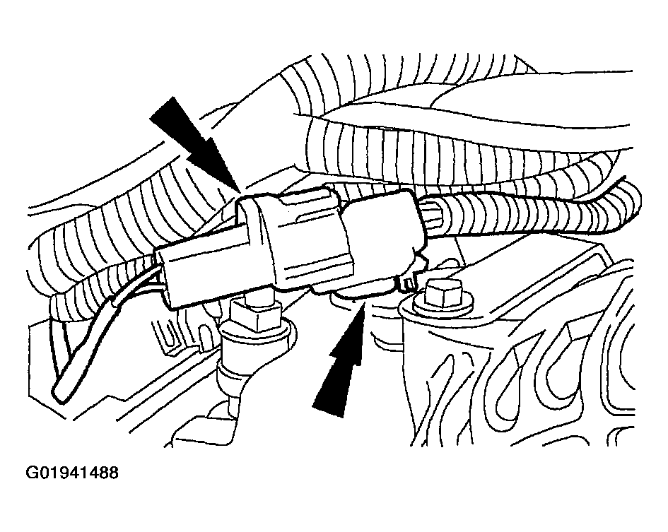
- Disconnect the fuel charging wiring electrical connector from the A/C compressor.
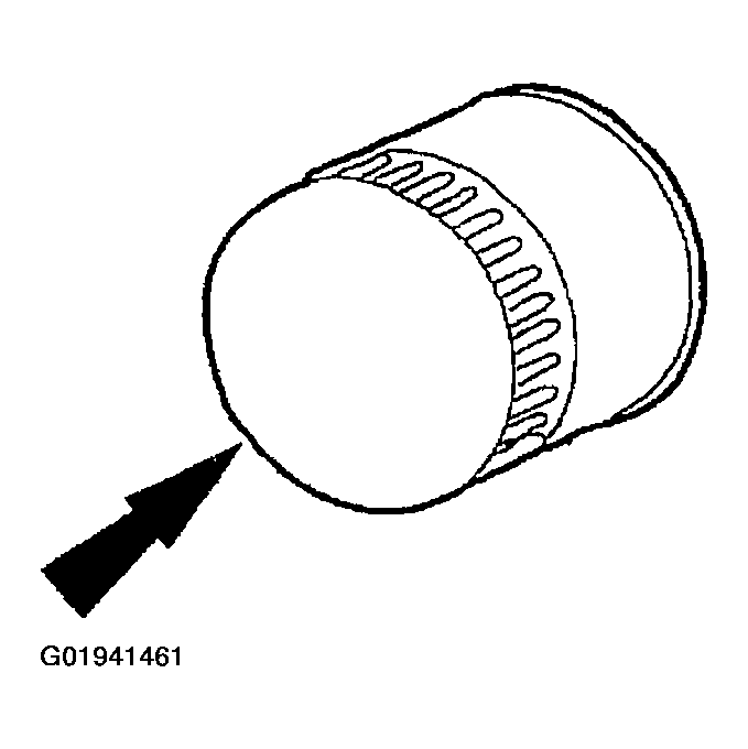
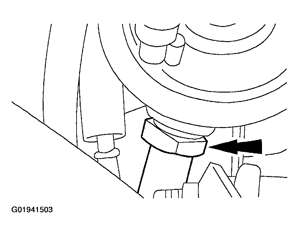
- Remove the oil bypass filter.
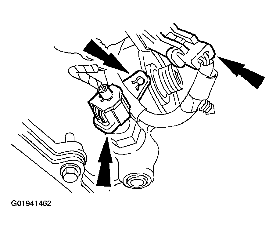
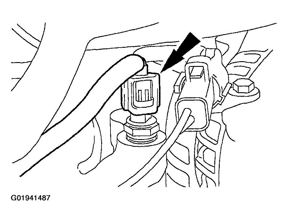
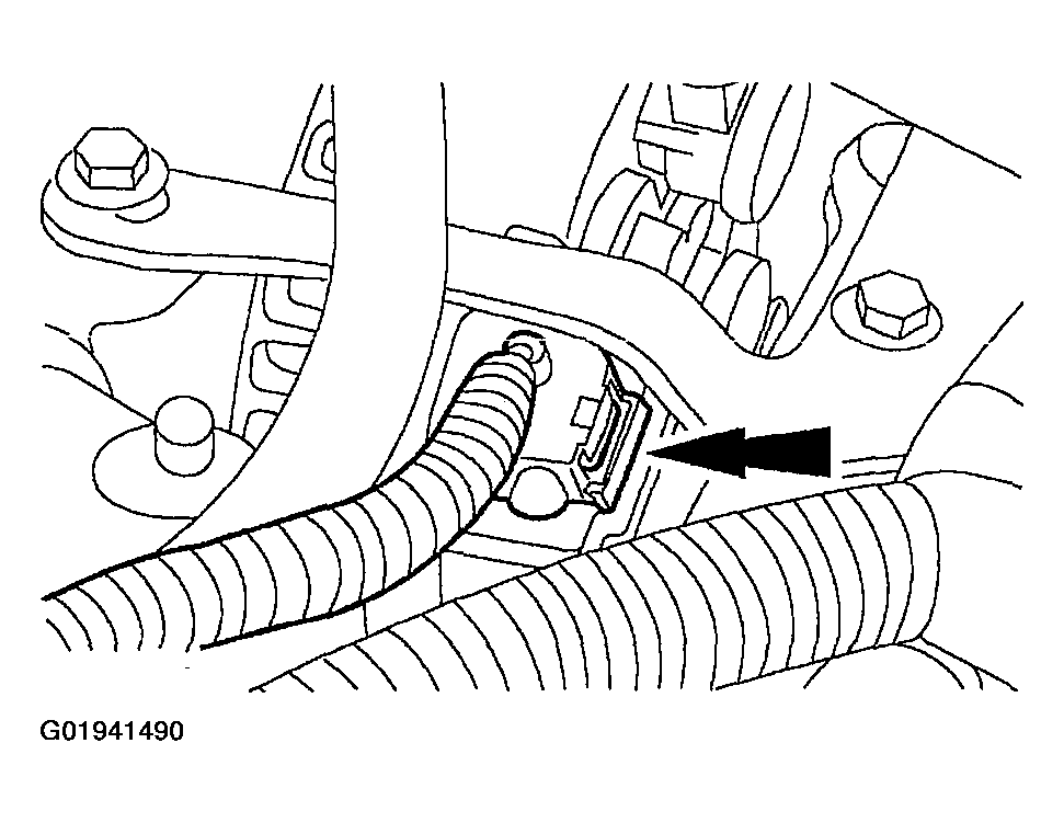
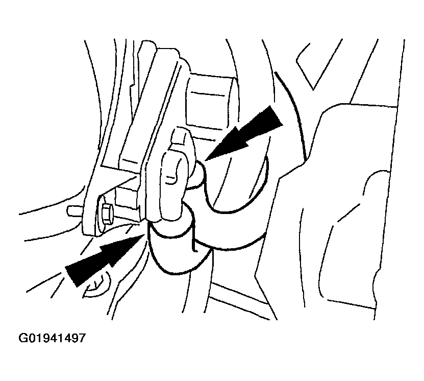
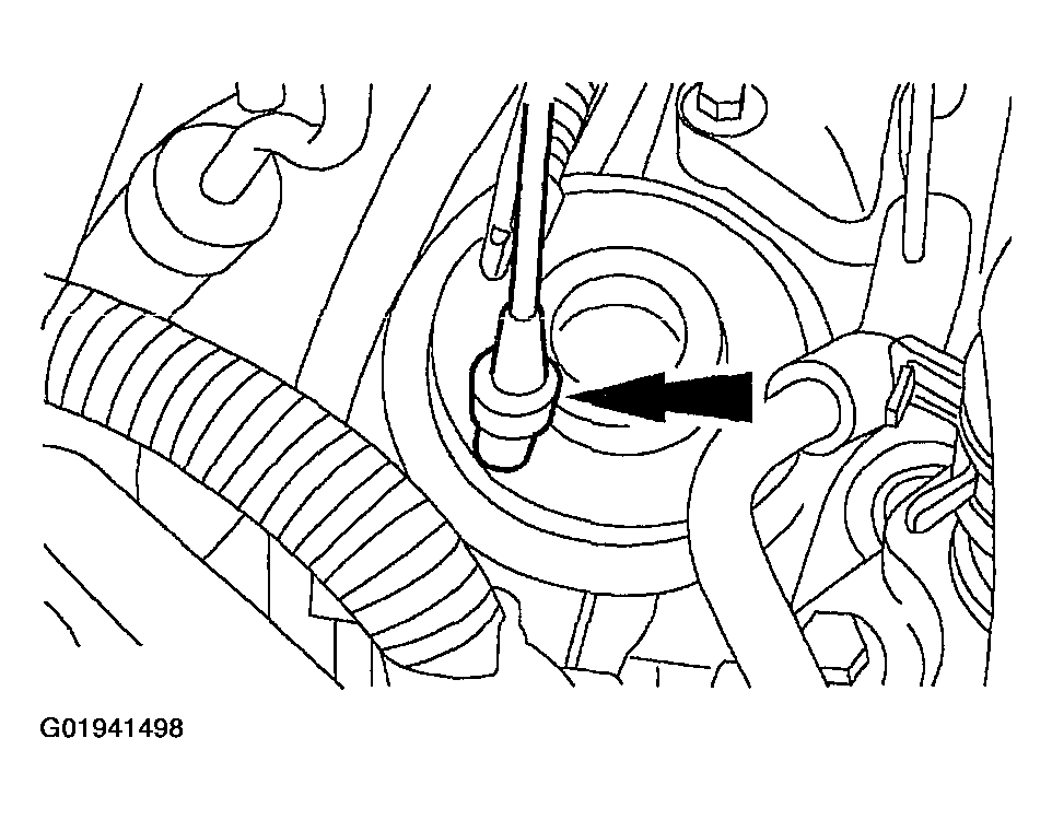
- Disconnect the electrical connection from the engine oil pressure (EOP) sensor, the power steering pressure (PSP) switch and the harness position retainer.
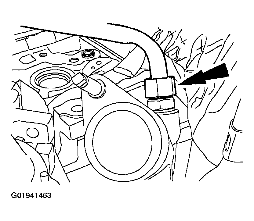
- Disconnect the exhaust gas recirculation (EGR) tube from the exhaust manifold connector.
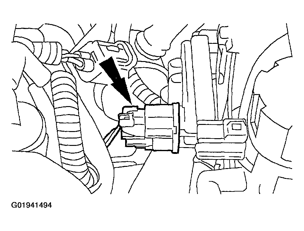
- Disconnect the differential pressure feedback EGR system connector.
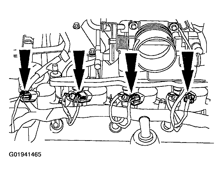
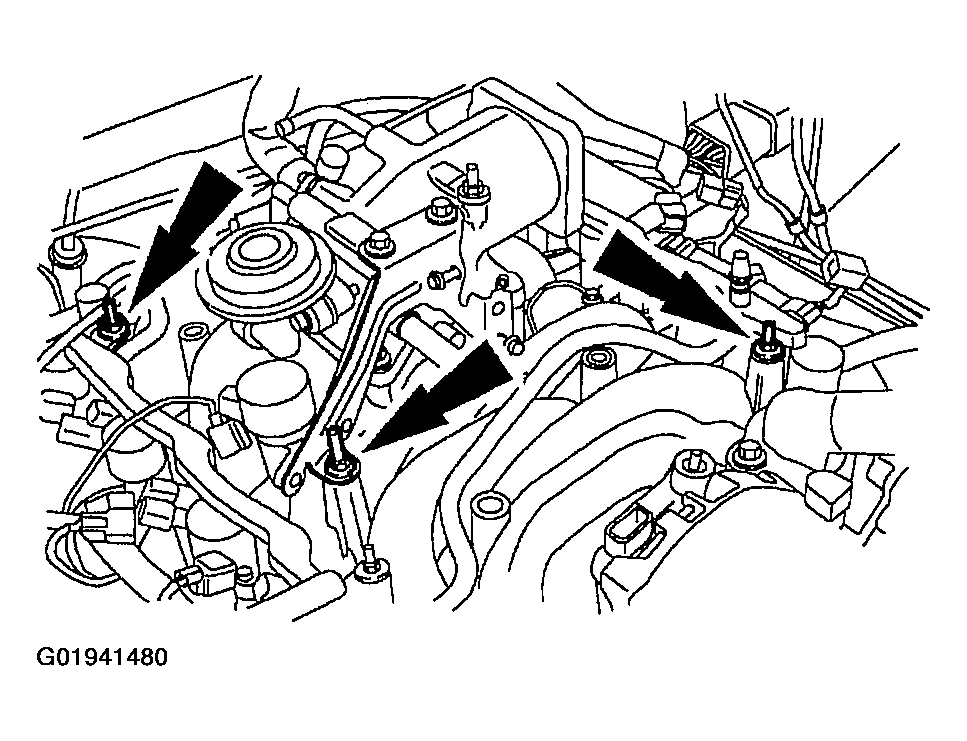
- Disconnect the fuel charging wiring electrical connectors from the eight ignition coils.
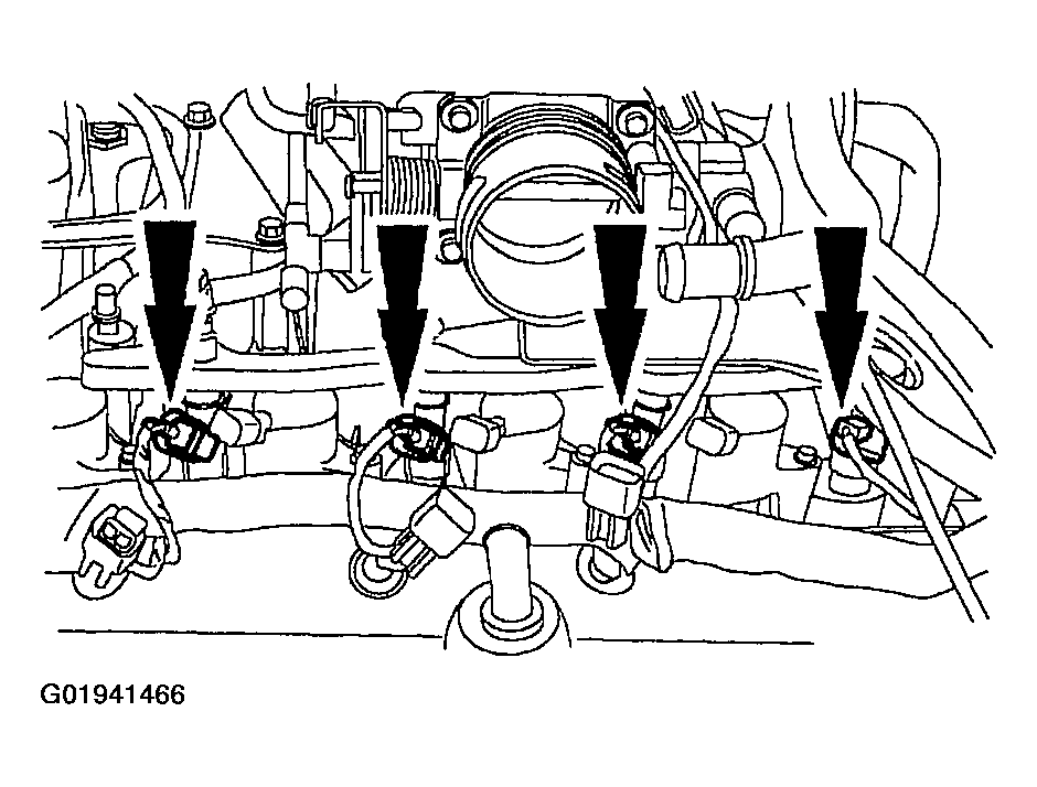
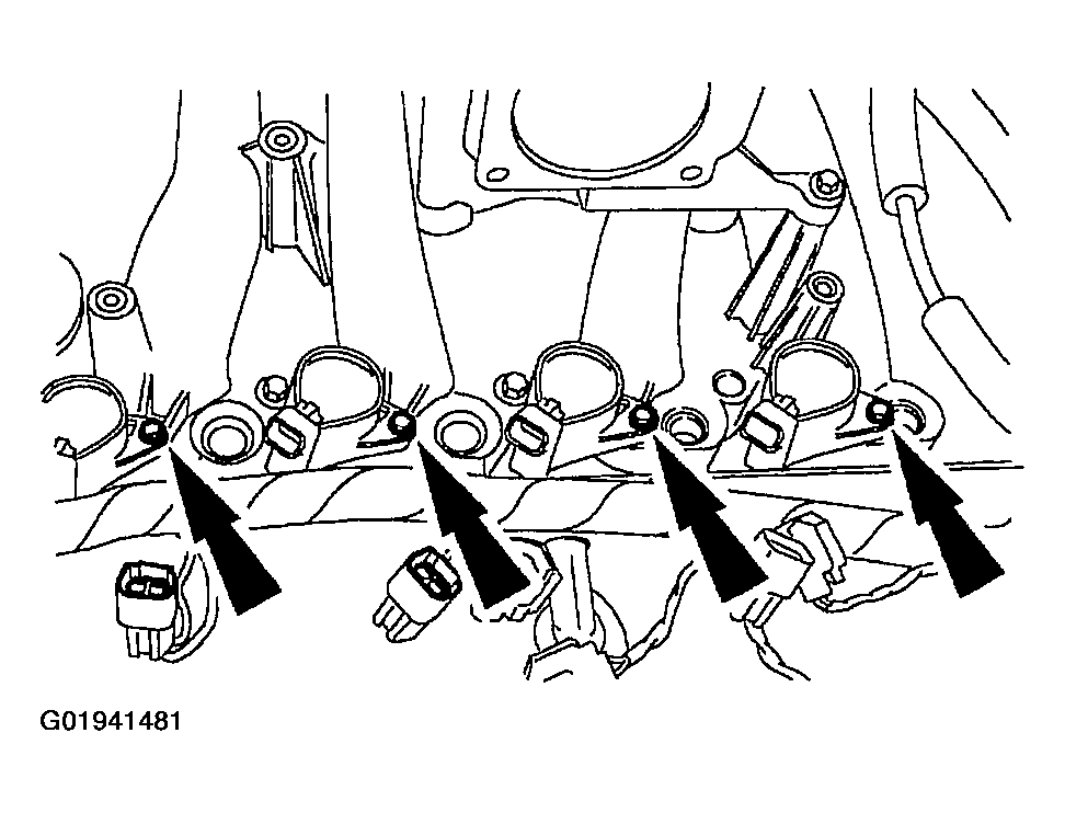
- Disconnect the fuel charging wiring electrical connectors from the eight fuel injectors.
Gasoline Engines
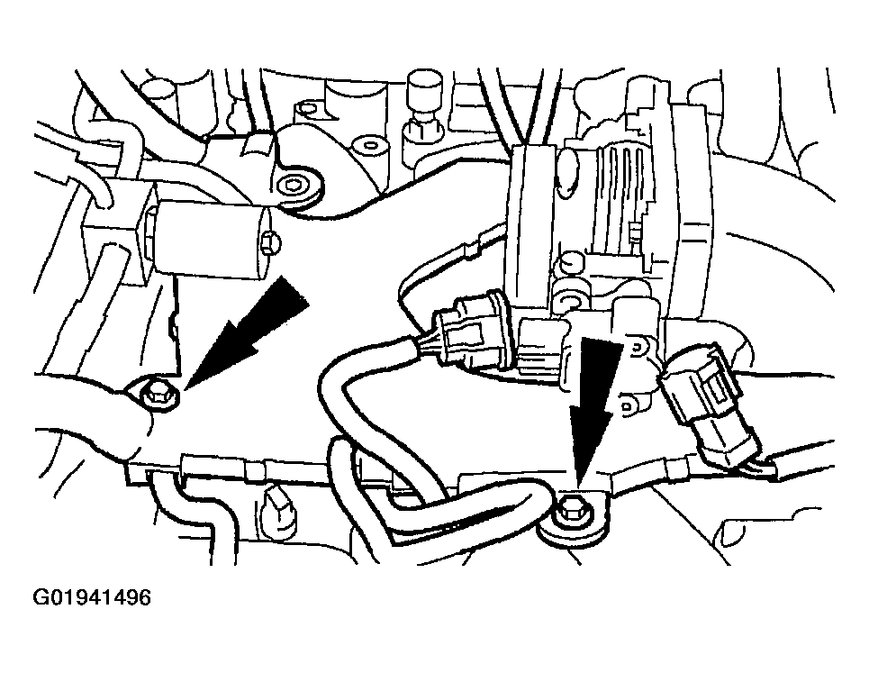
- Remove the bolts and the EGR tube heat shield.
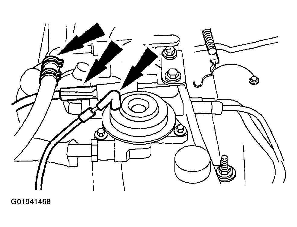
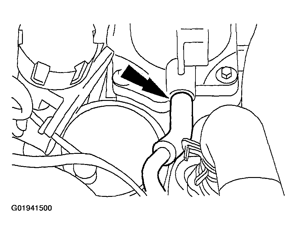
- Disconnect the vacuum hoses for the evaporative emission (EVAP) canister purge valve, the main chassis hose and the EGR valve.
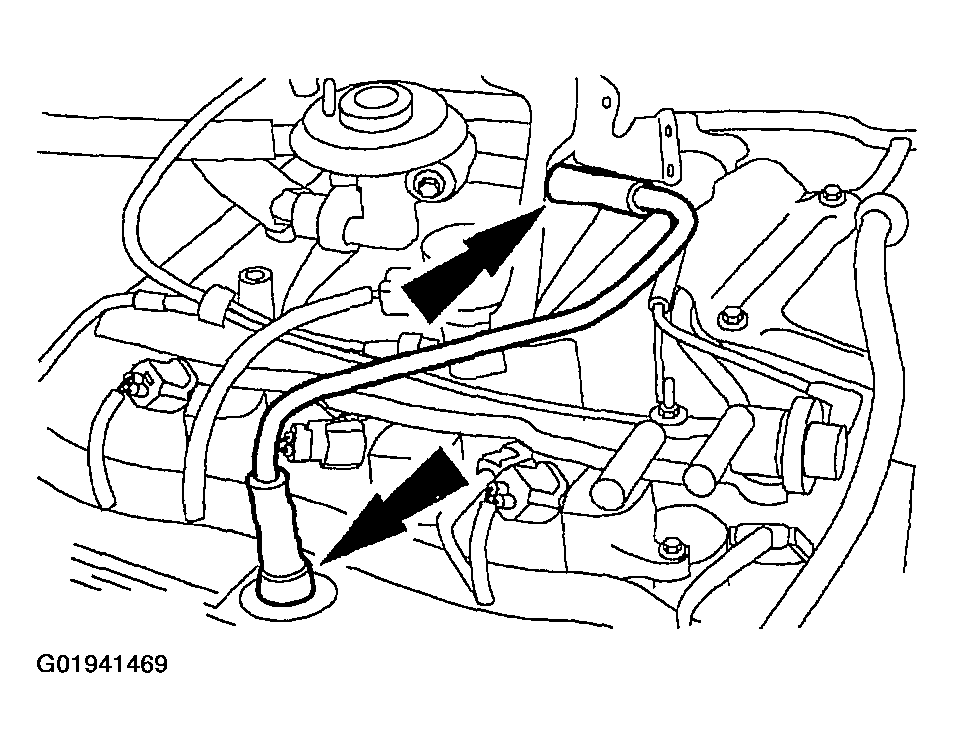
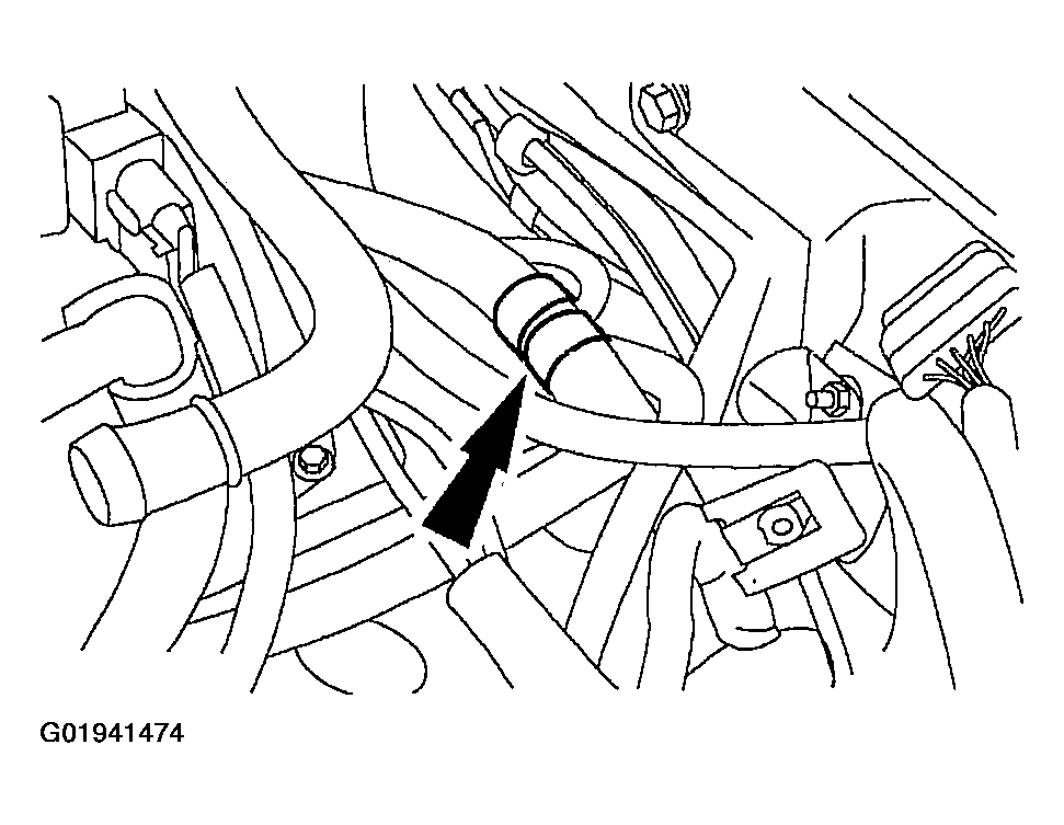
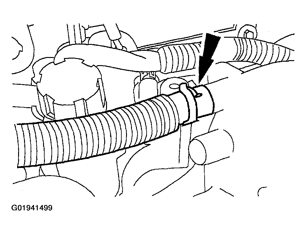
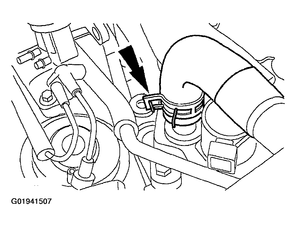
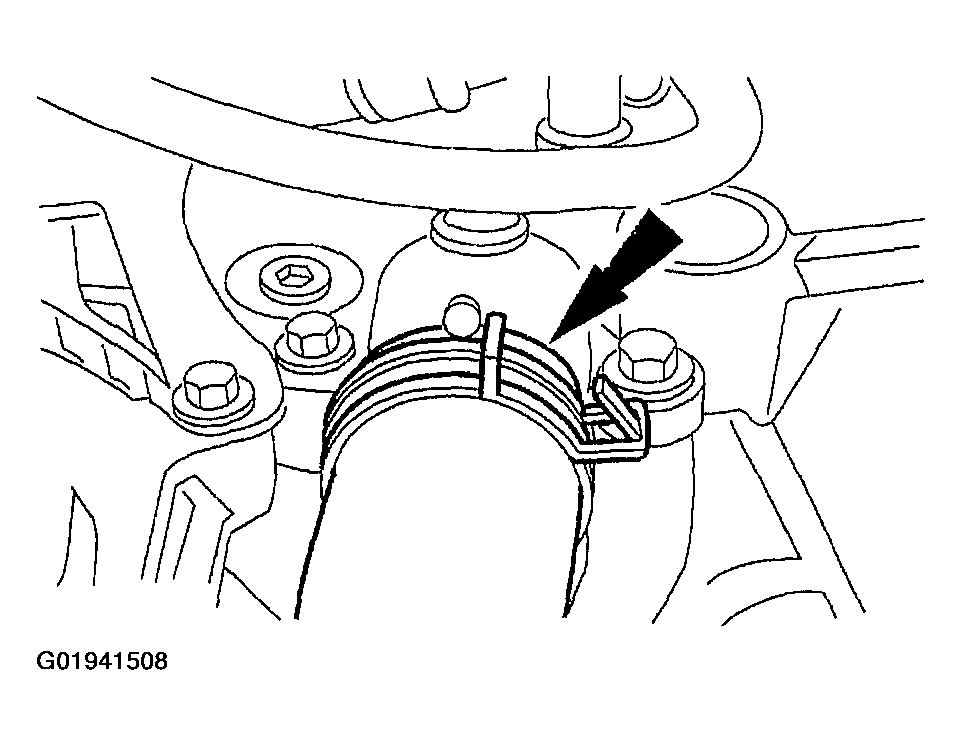
- Disconnect and remove the crankcase ventilation tube.
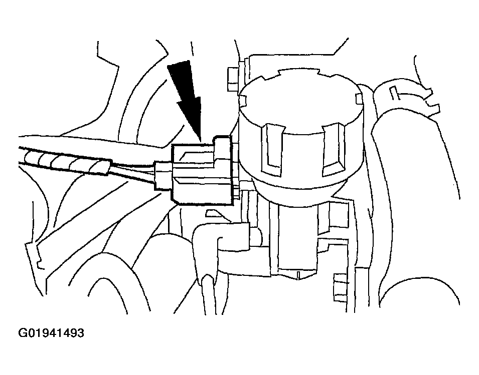
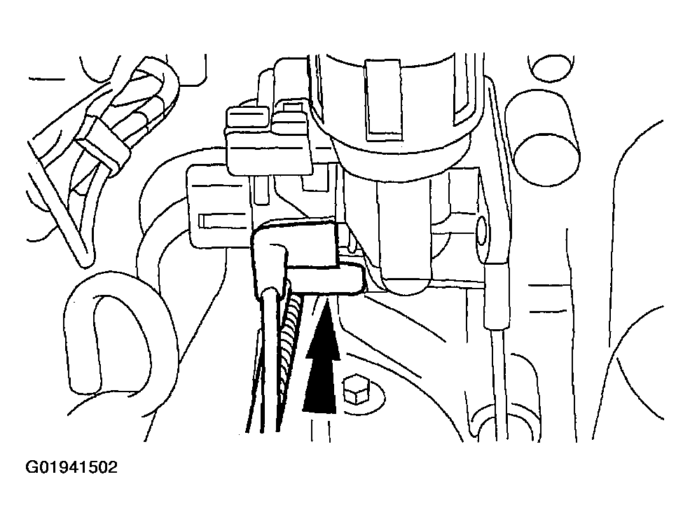
- Disconnect the fuel charging wiring electrical connector from the EGR vacuum regulator solenoid.
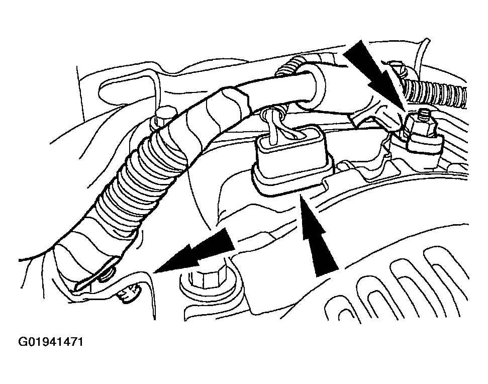
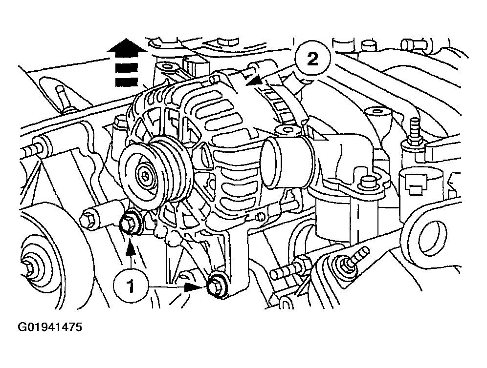
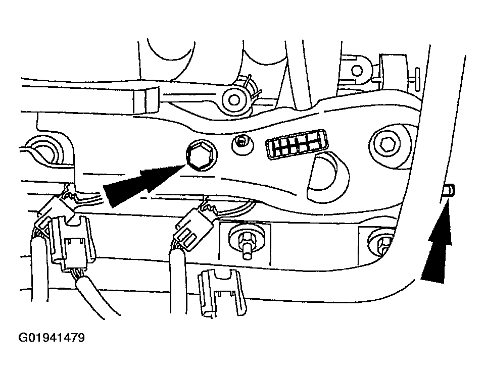
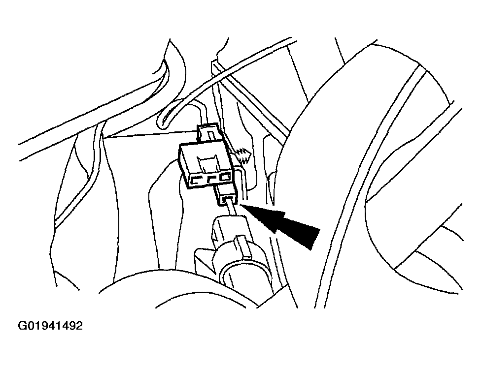
- Disconnect the electrical connector from the generator, generator cable and pin-type harness retainer.
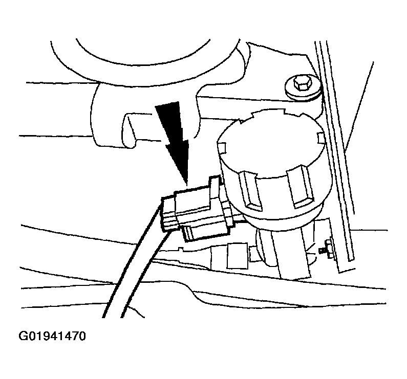
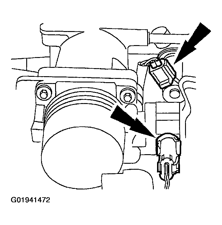
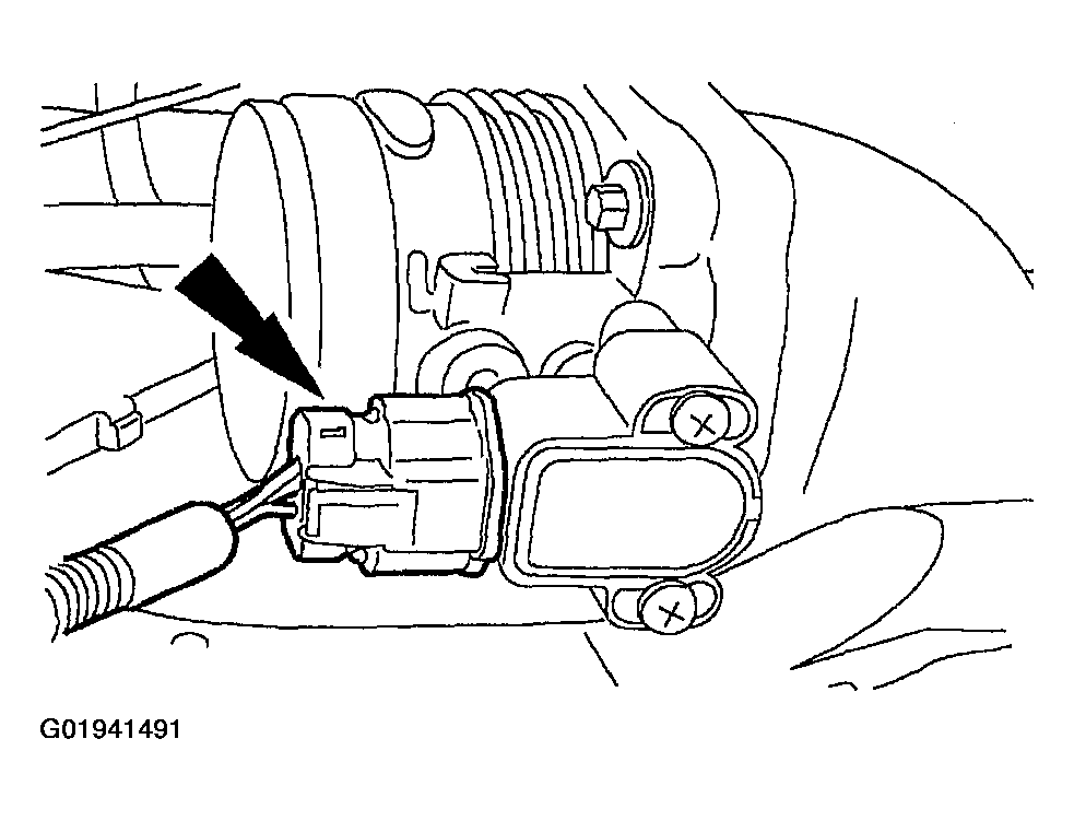
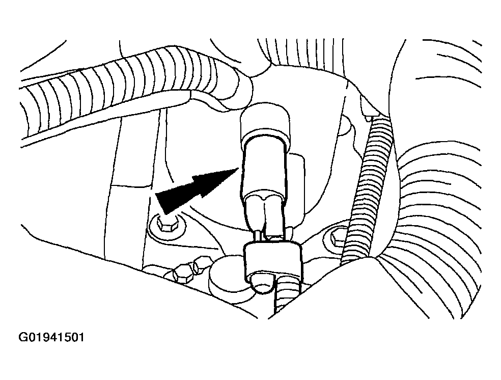
- Disconnect the electrical connector from the idle air control (IAC) and the throttle position (TP) sensor.
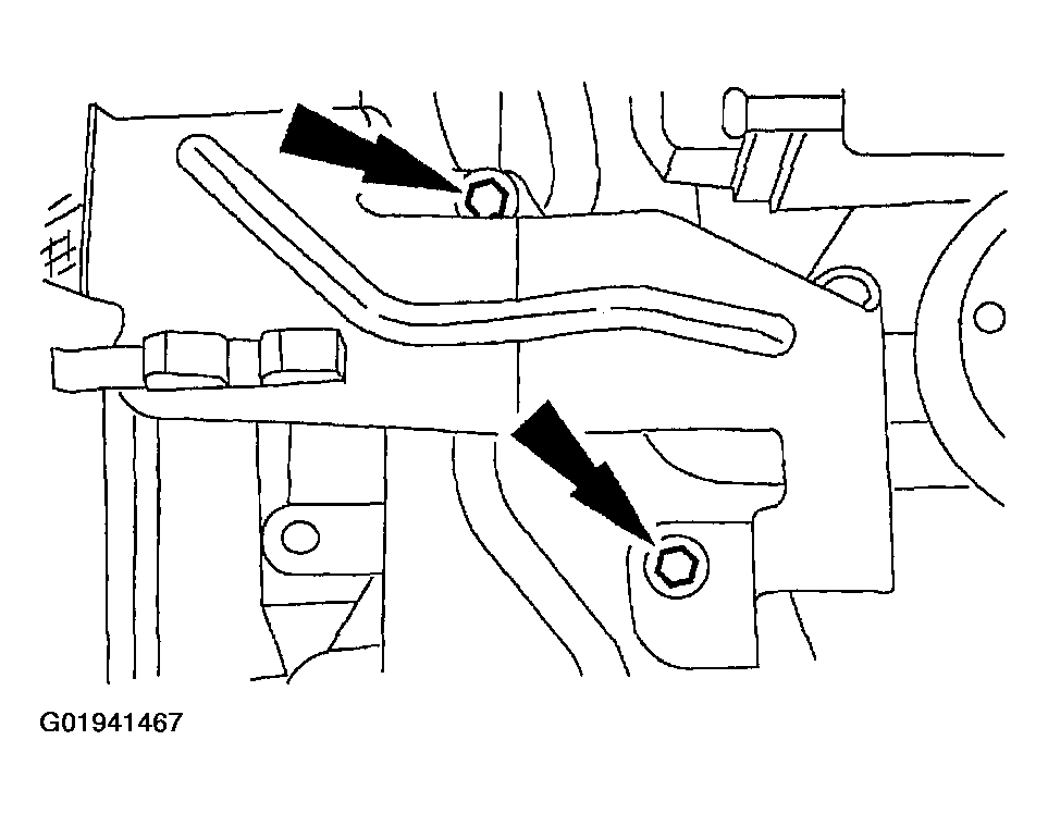
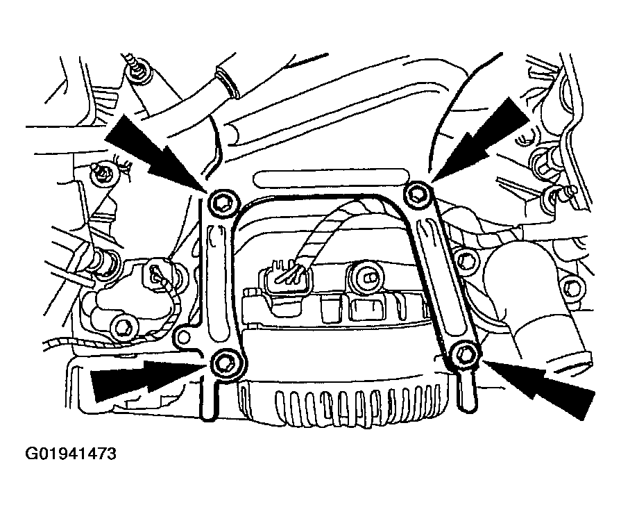
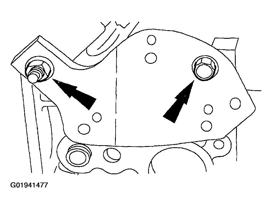
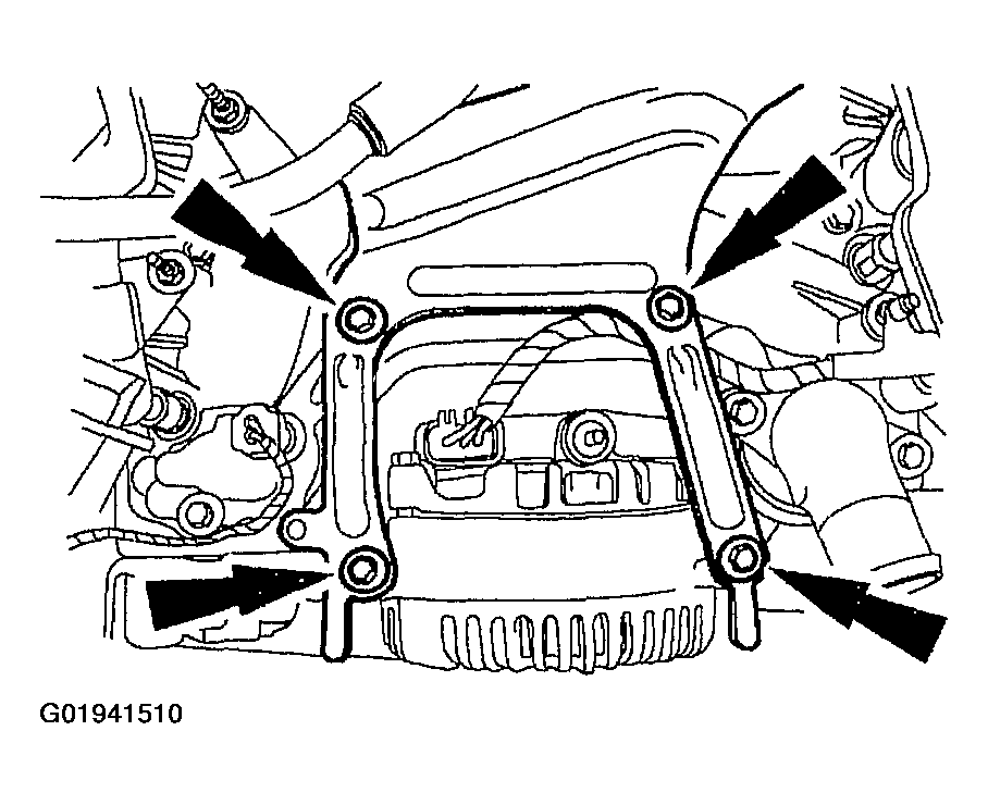
- Remove the generator mounting bracket.
- Remove the bolts.
- Remove the bracket.
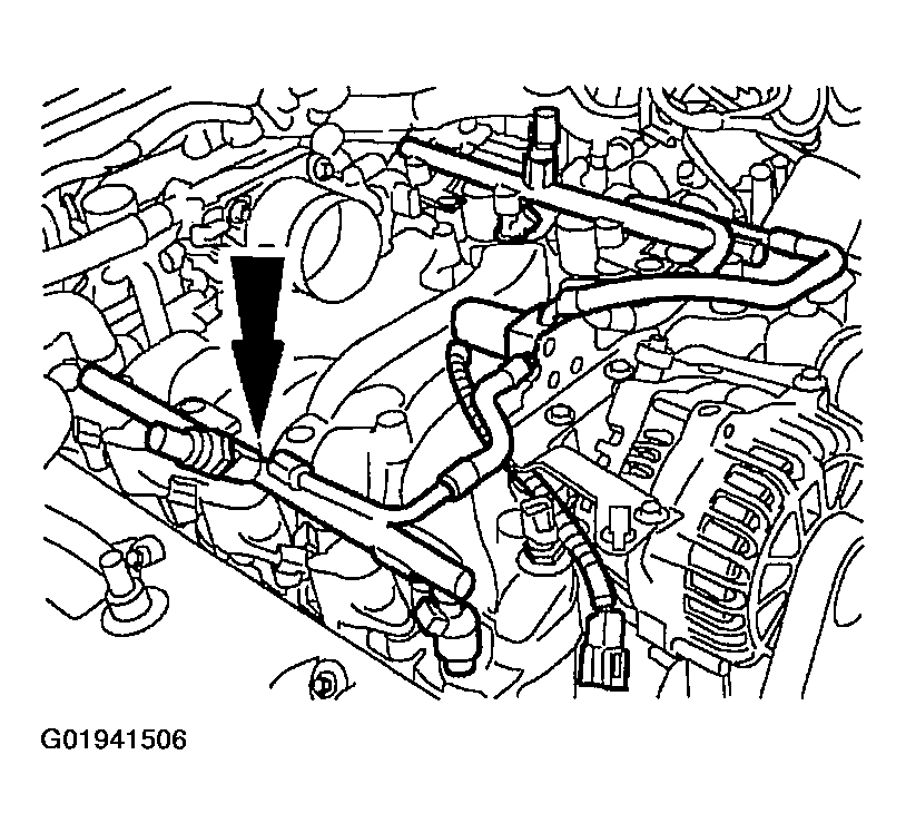
- Disconnect the fuel charging wiring from the crash bracket and the wiring support bracket and remove the harness from the engine assembly.
- Remove the generator.
- Remove the bolts.
- Remove the generator.
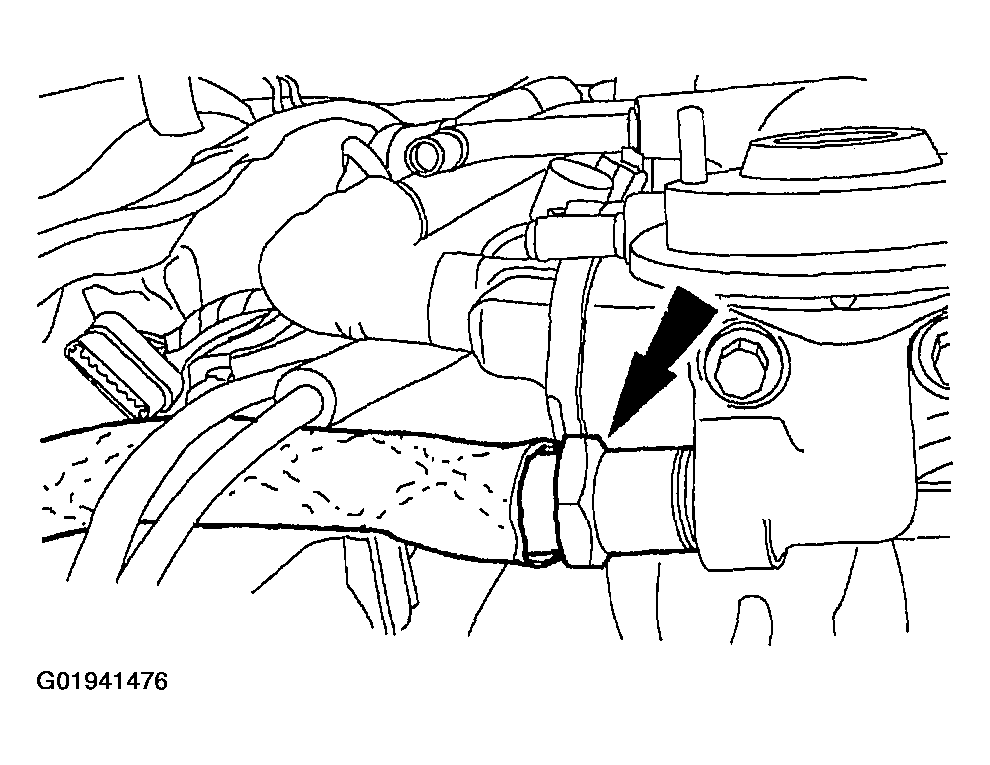
- Disconnect the EGR tube from the EGR valve.
- Remove the bolt and nut, and remove the transmission wiring support bracket.
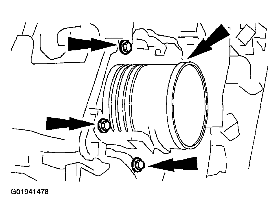
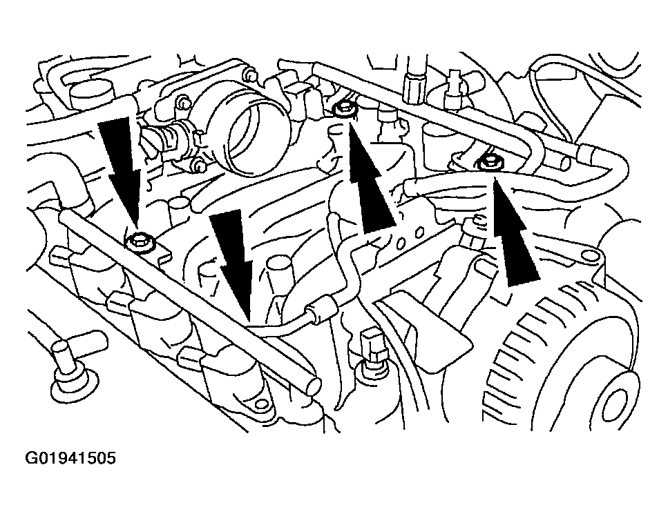
- Remove the four bolts and the throttle body.
- Remove the bolt and the stud. Remove the crash bracket.
- Remove the studs and the fuel injection supply manifold and fuel injectors as an assembly.
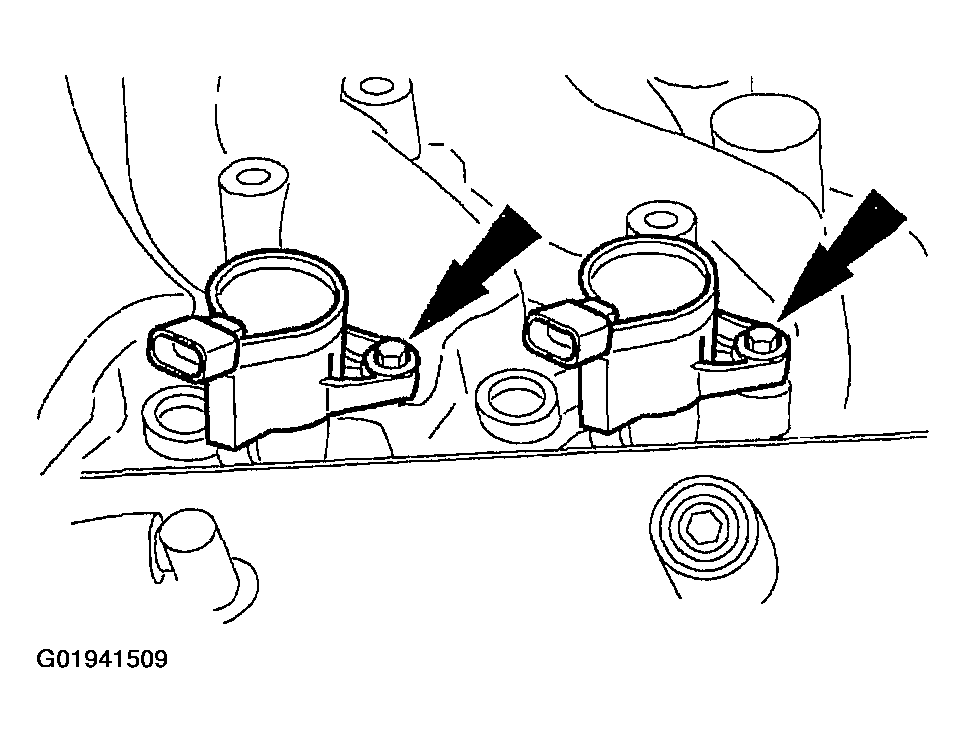
- Remove the eight bolts and the eight ignition coils.
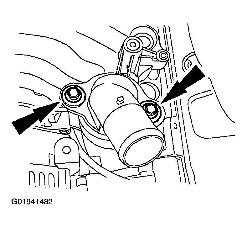
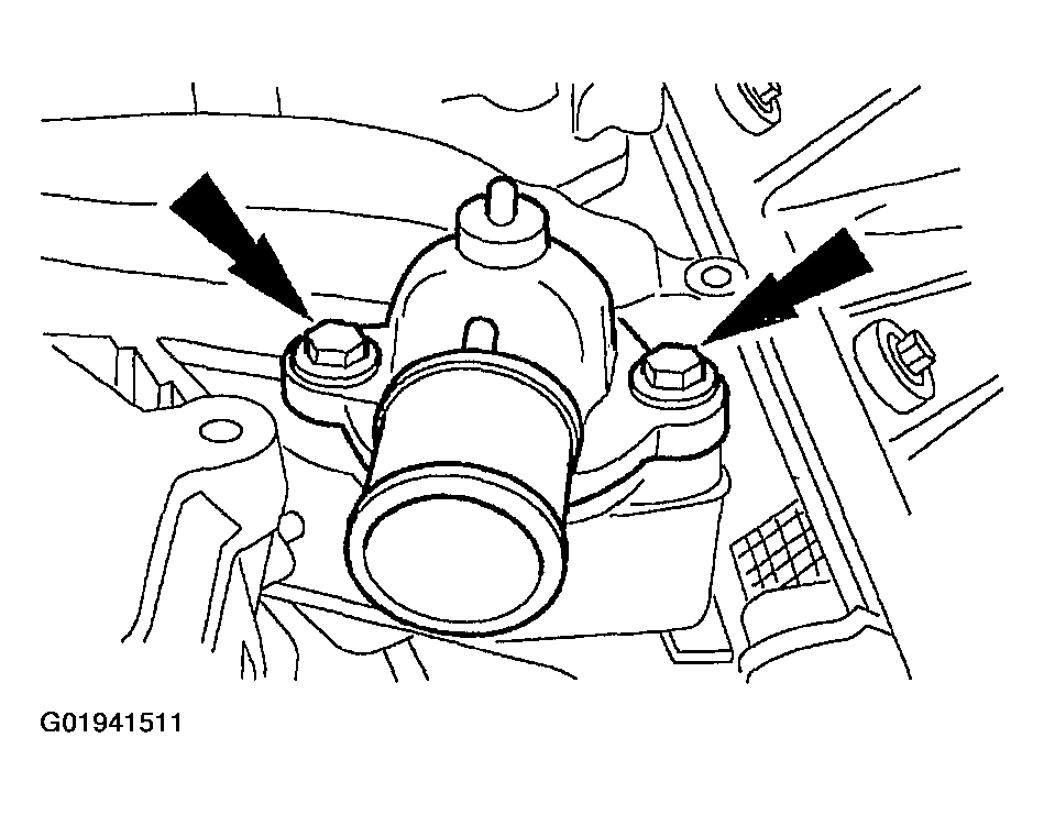
- Remove the bolts and the water outlet adapter.
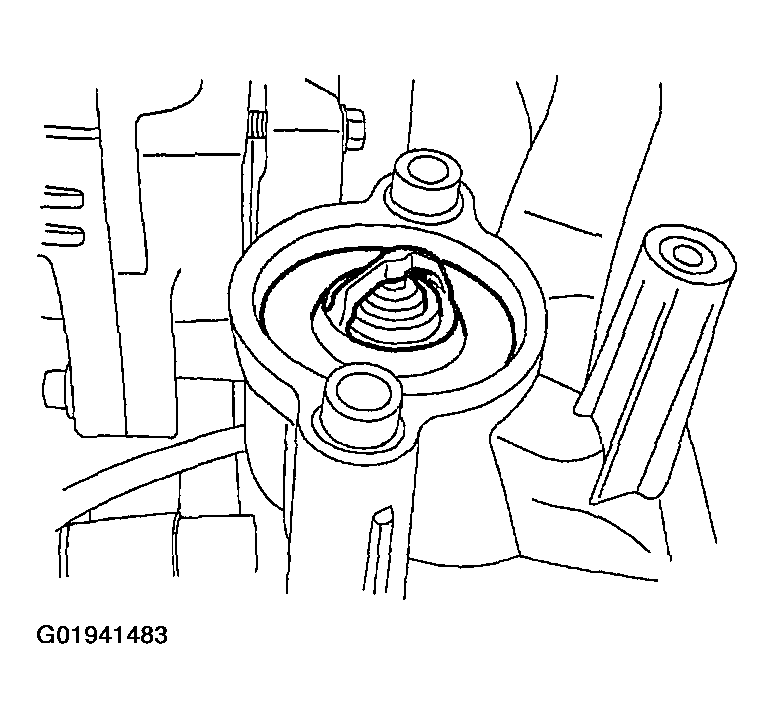
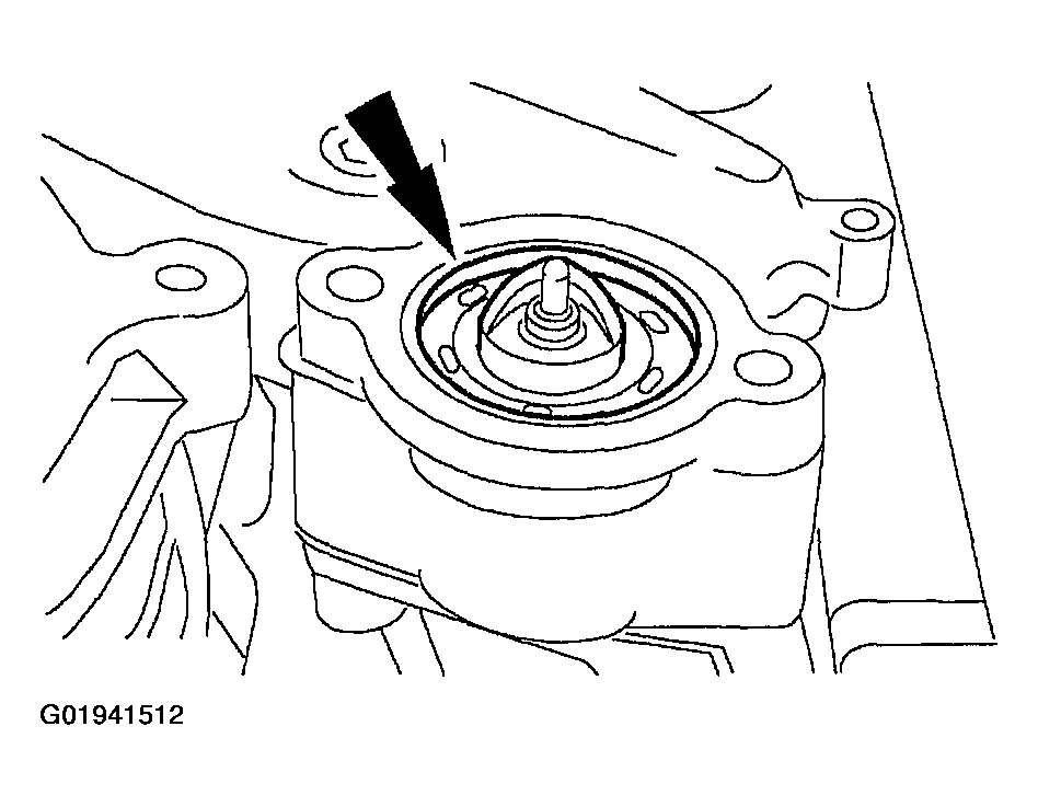
- Remove the water thermostat.
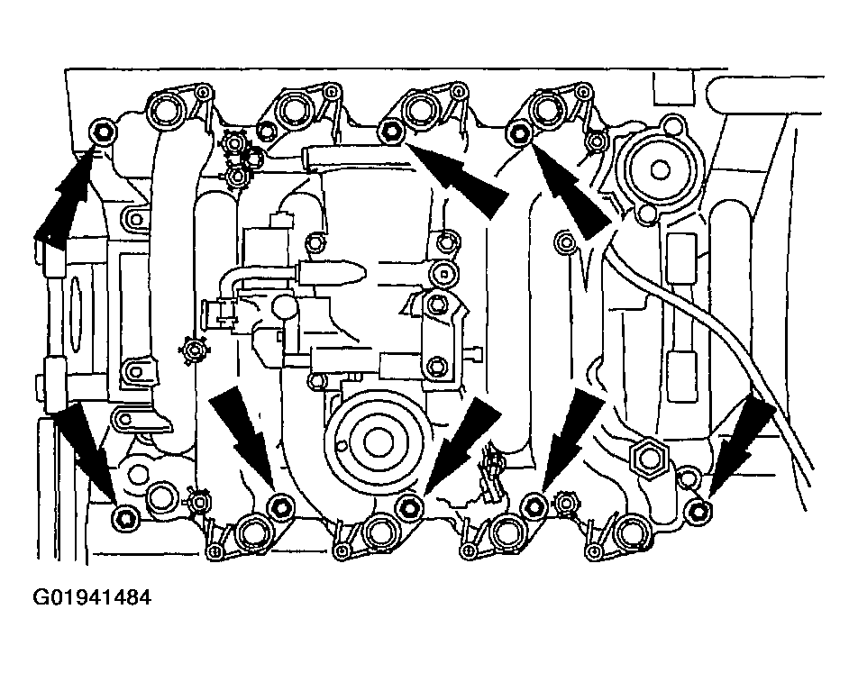
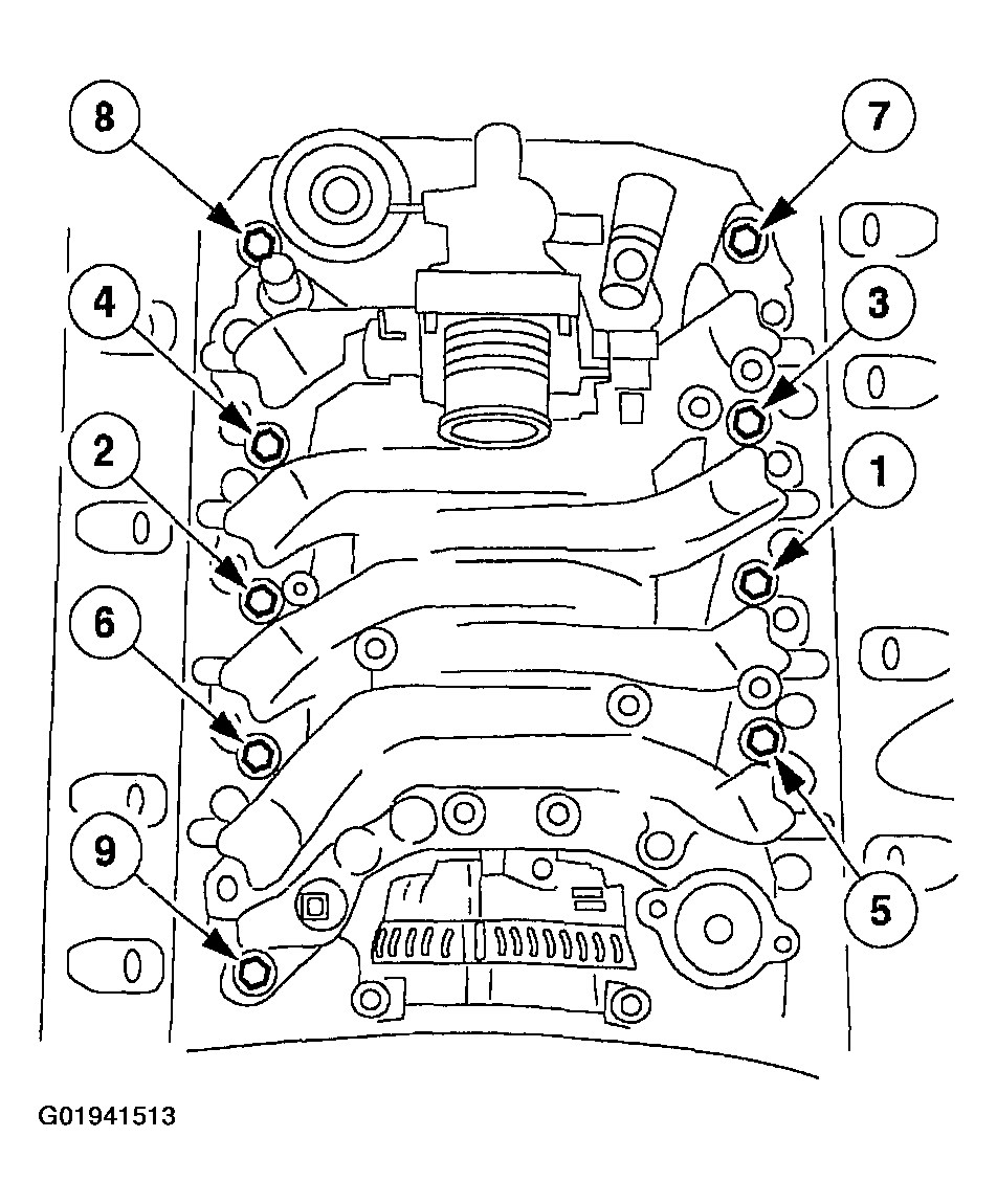
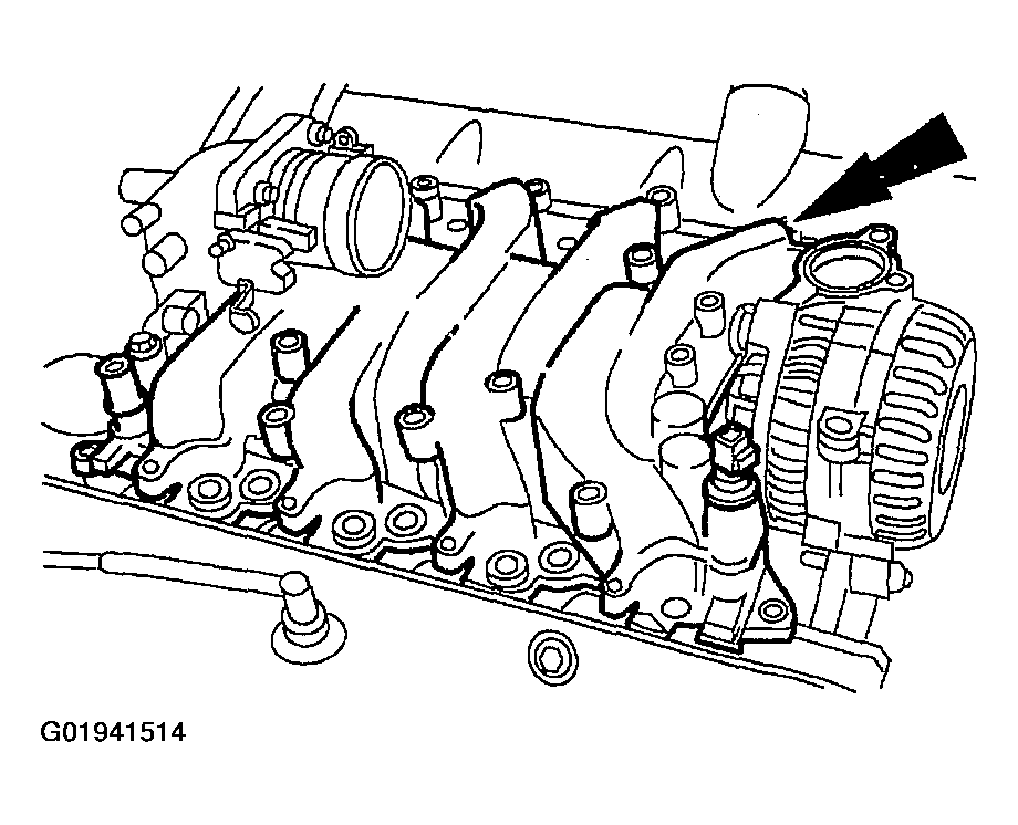
- Remove the bolts and the intake manifold.
Natural Gas Engines
- Disconnect the fuel charging wiring electrical connector from the fuel pressure sensor.
- Disconnect the fuel charging wiring electrical connector from the fuel temperature sensor.
- Disconnect the fuel charging wiring electrical connector from the engine coolant temperature sensor.
- Separate the isolation valve wiring lead from the generator support bracket and disconnect.
- Disconnect the fuel charging wiring electrical connector from the camshaft position sensor.
- Disconnect the fuel charging wiring electrical connector from the generator.
- Disconnect the fuel charging wiring electrical connector from the throttle position sensor.
- Disconnect the fuel charging wiring from the radio ignition interference capacitor.
- Disconnect the fuel charging wiring from the EGR vacuum regulator solenoid.
- Disconnect the fuel charging wiring from the differential pressure feedback EGR.
- Disconnect the fuel charging wiring from the idle air control valve.
- Remove the bolts and position the fuel charging wiring out of the way.
- Disconnect the hoses from the differential pressure feedback EGR.
- Disconnect the vacuum hose from the exhaust gas recirculation (EGR) valve.
- Disconnect the main chassis vacuum supply hose from the throttle body adapter.
- Disconnect the crankcase ventilation tube at two locations and remove.
- Disconnect the vacuum hose from the throttle body adapter.
- Disconnect the vacuum hoses from the EGR vacuum regulator solenoid.
- Disconnect the EGR tube from the EGR valve.
- Remove the bolts from the isolation valve.
- Remove the four bolts.
- Remove the fuel injection supply manifold and the fuel injectors as an assembly.
- Disconnect the heater water hose from the intake manifold.
- Disconnect the upper radiator hose from the water outlet adapter.
- Remove the bolts and the eight ignition coils.
- Remove the bolts and the generator support bracket.
- Remove the bolts and the water outlet adapter.
- Remove the water thermostat and the O-ring.
- Remove the bolts.
- Remove the intake manifold.
All Engines
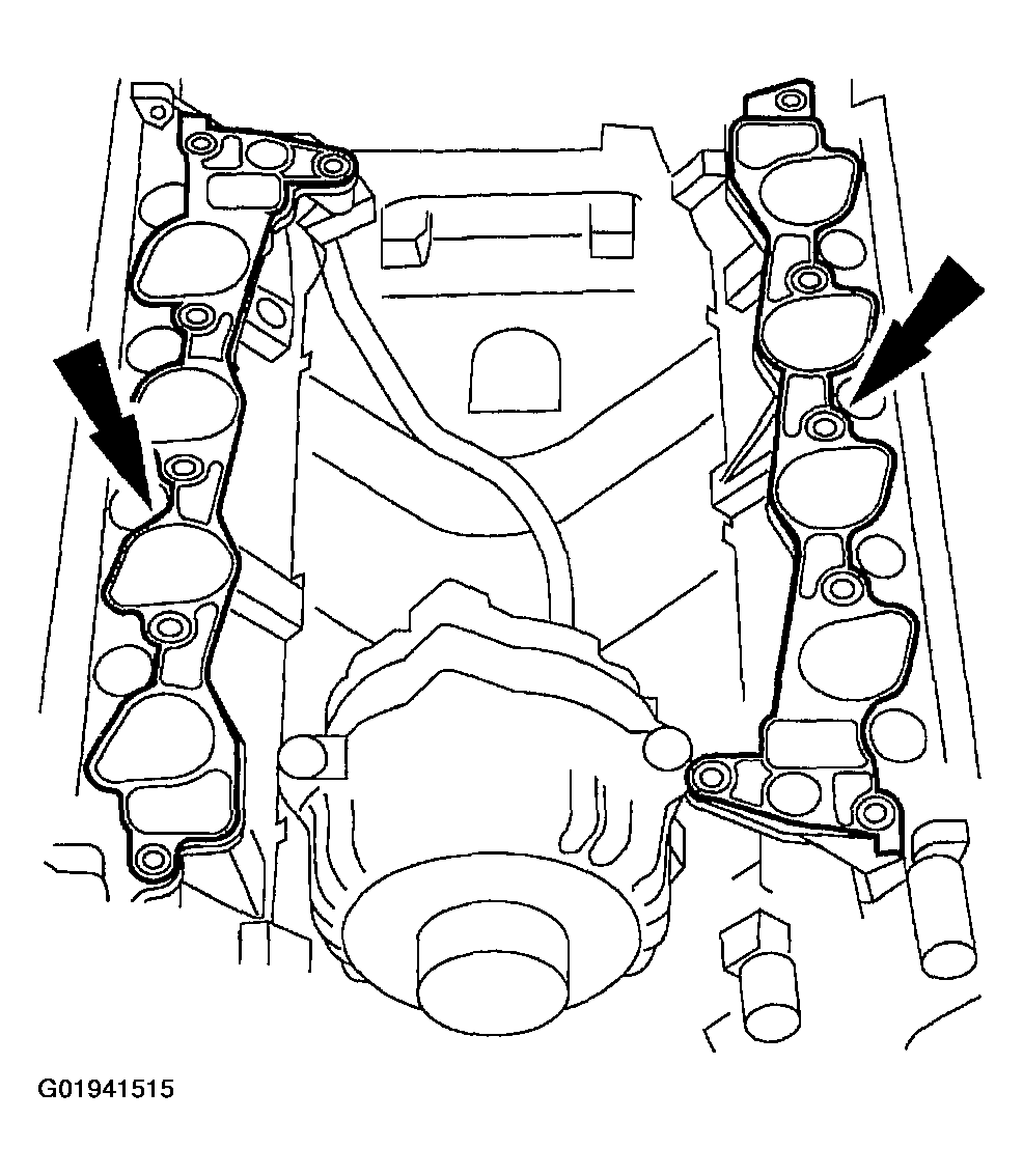
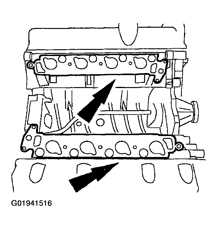
- Remove the intake manifold gaskets.
- Clean the sealing surfaces.
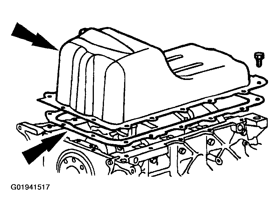
- Remove the oil pan.
- Remove the bolts.
- Remove the oil pan.
- Remove the oil pan gasket.
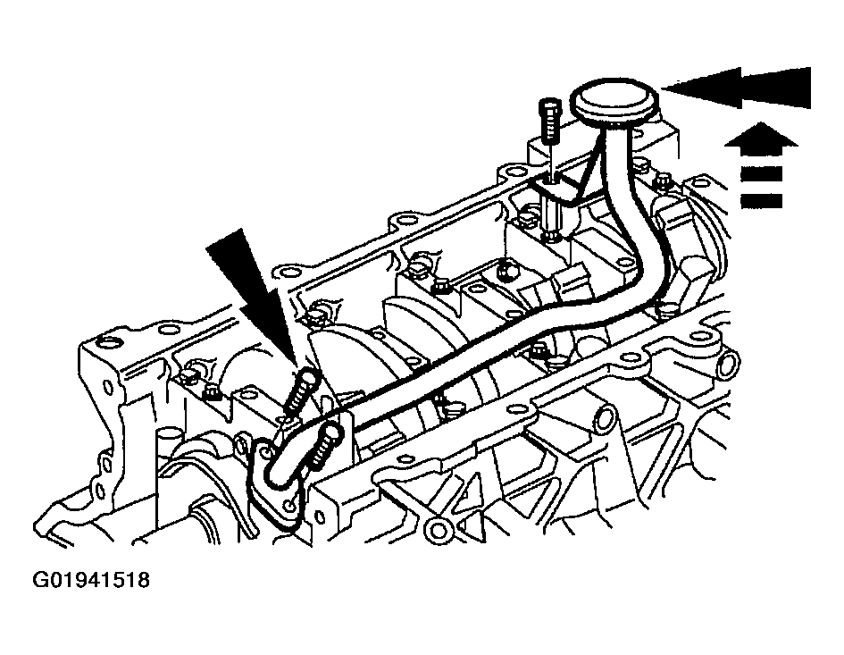
- Remove the bolts and the oil pump screen cover and tube.
- Remove the oil pump screen cover and tube spacer.
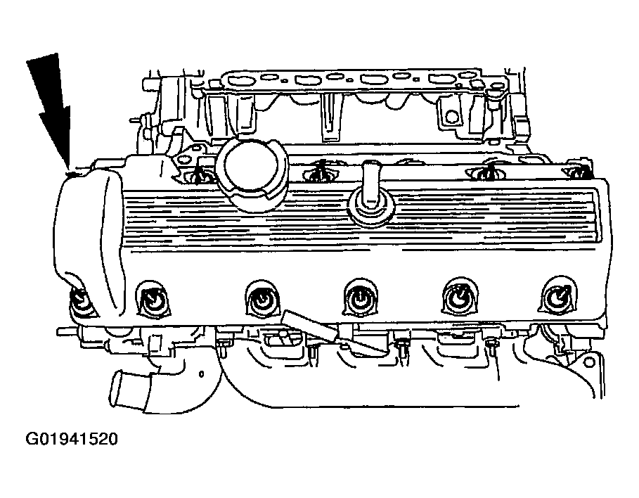
- Remove the studs and bolts, and remove the valve cover.
- Discard the valve cover gasket and clean the mating surface of the cylinder head.
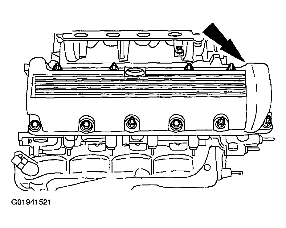
- Remove the studs and bolts and remove the right valve cover.
- Discard the valve cover gasket and clean the mating surface of the cylinder head.
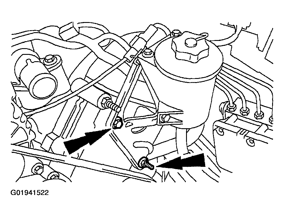
- Remove the bolt and the studs and position the reservoir aside.
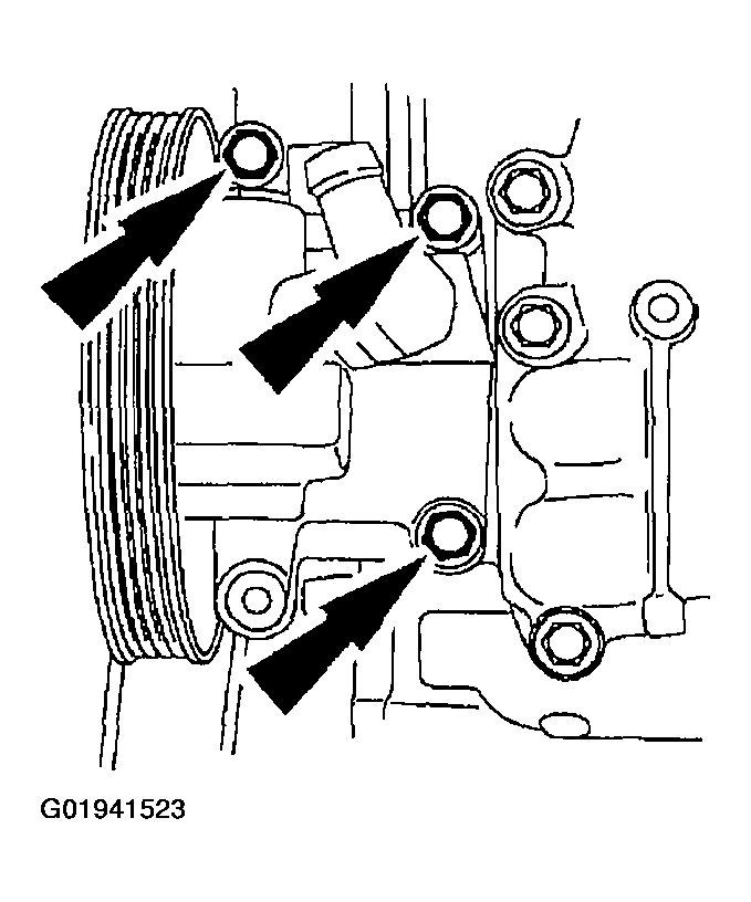
- Remove the bolts and set aside the power steering pump.
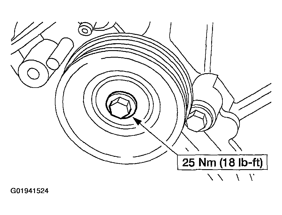
- Remove the bolt and the belt idler pulley.
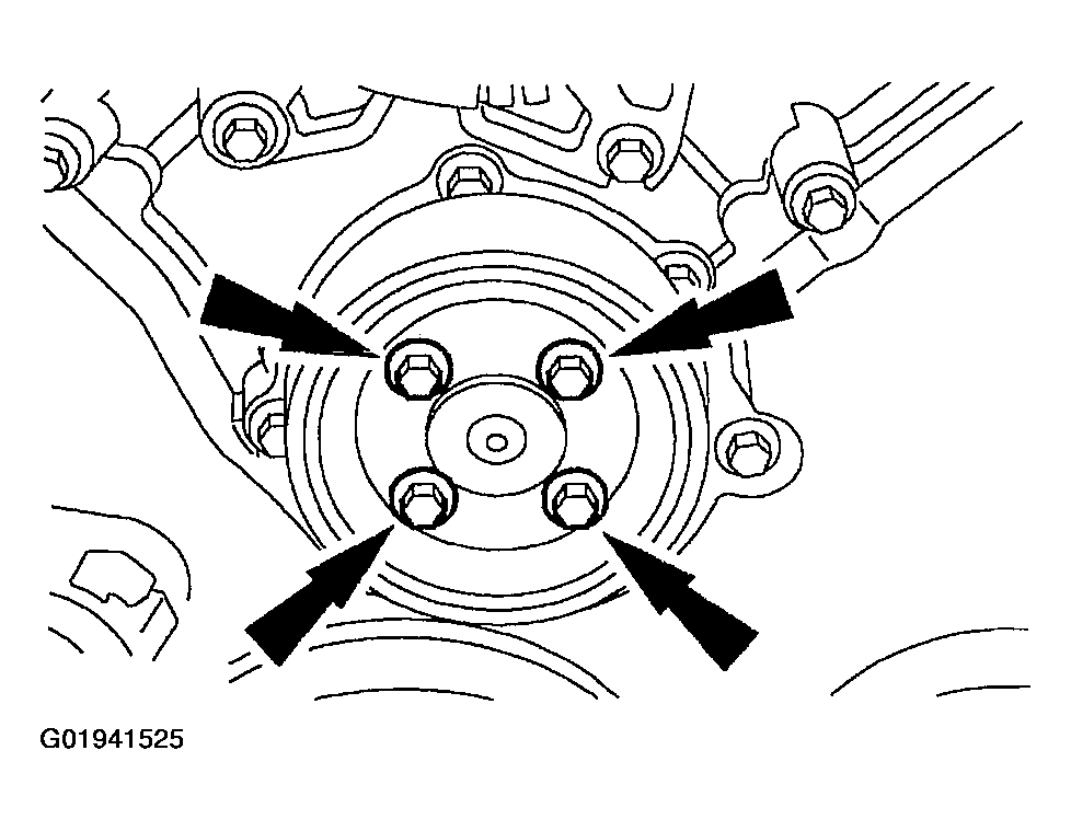
- Remove the water pump pulley. Refer to WATER PUMP under REMOVAL AND INSTALLATION.
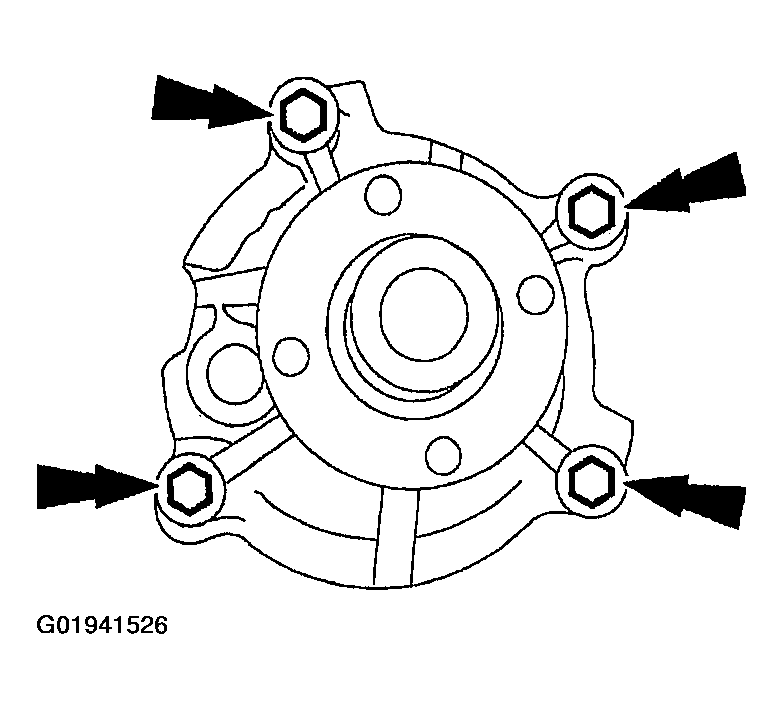
- Remove the bolts and the water pump. Refer to WATER PUMP under REMOVAL AND INSTALLATION.
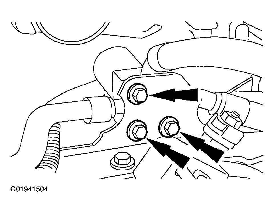
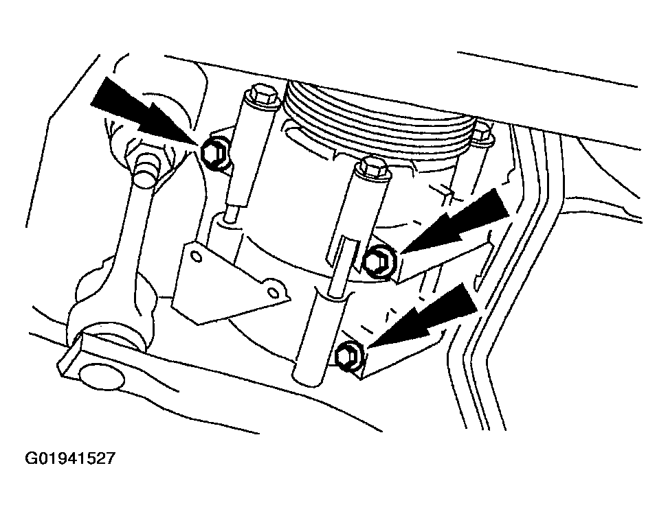
- Remove the bolts and the A/C compressor.
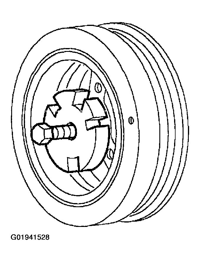
- Remove the crankshaft pulley bolt. Use the Crankshaft Damper Remover to remove the crankshaft pulley.
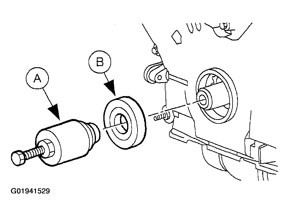
- Use the (A) Front Cover Seal Remover to remove the (B) crankshaft front seal.
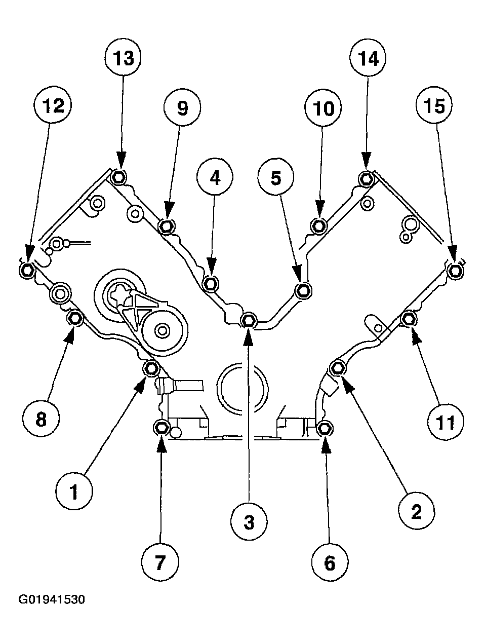
- Remove the fasteners.
- Remove the engine front cover from the cylinder block.
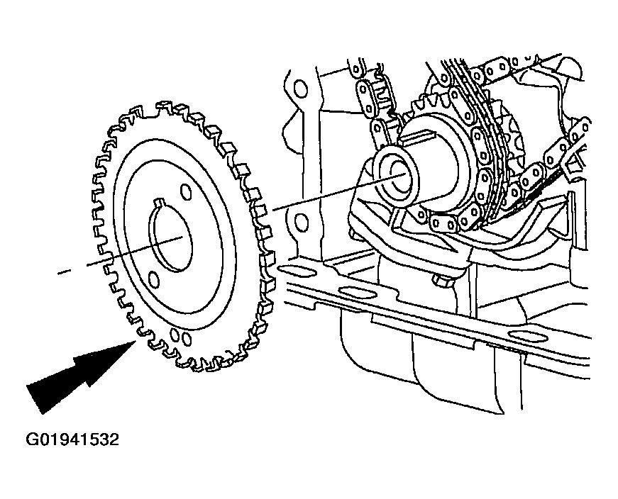
- Remove the crankshaft sensor ring from the crankshaft (6303).
- Position the crankshaft with the Crankshaft Holding Tool as shown.
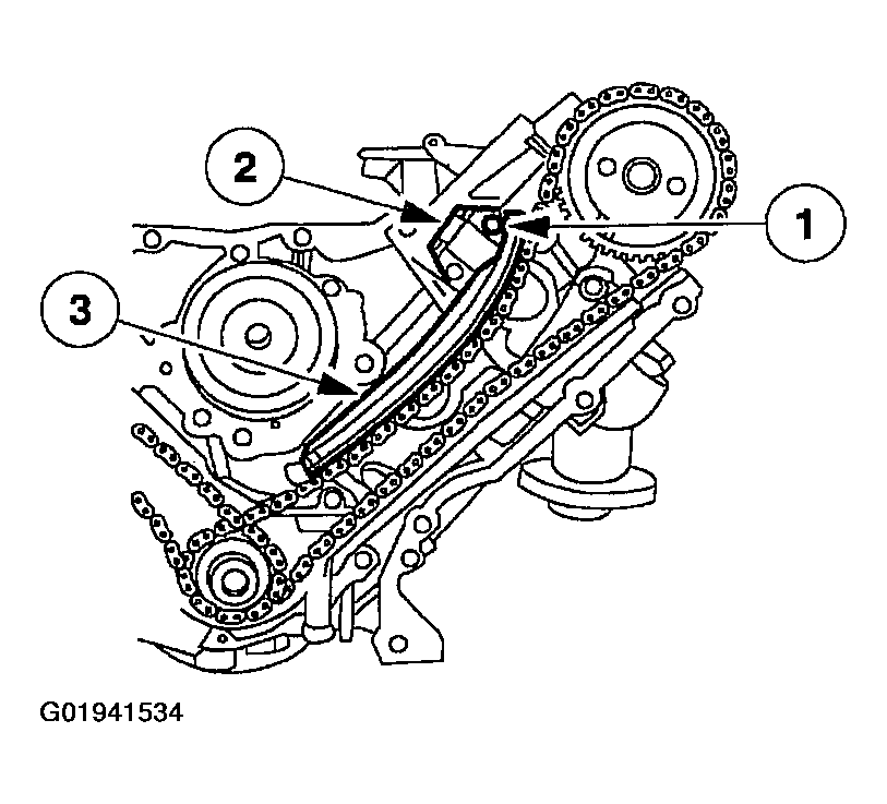
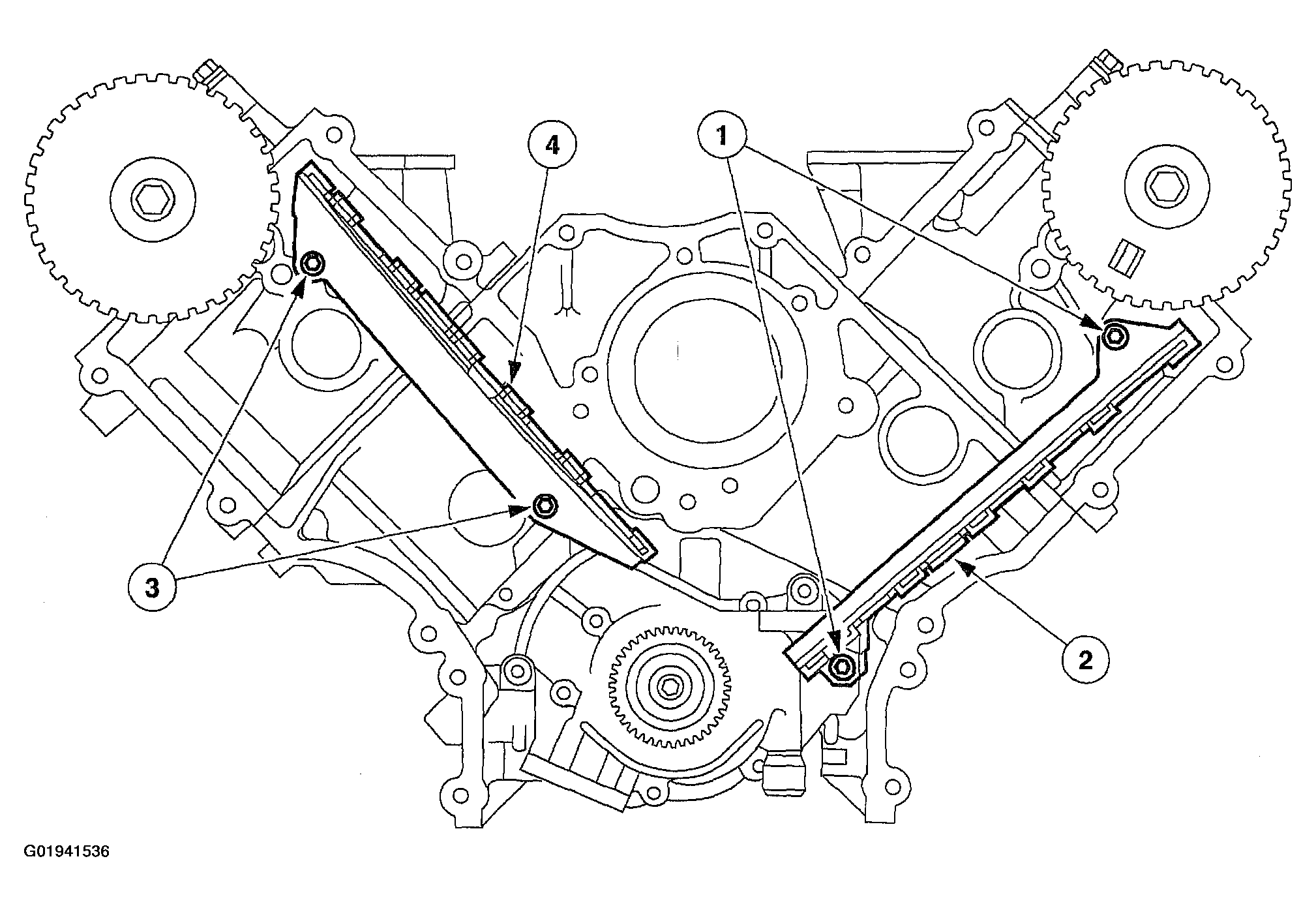
- Remove the timing chain tensioning system from both timing chains.
- Remove the bolts.
- Remove the timing chain tensioners.
- Remove the timing chain tensioner arms.
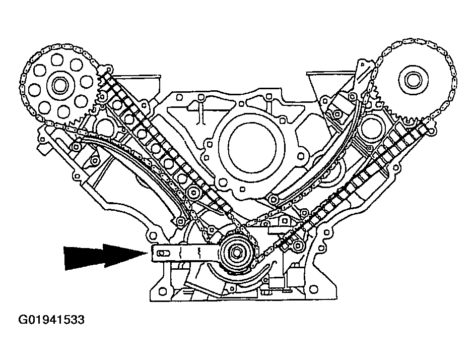
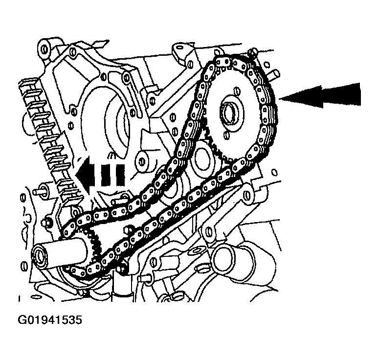
- Remove the LH and RH timing chains and the crankshaft sprockets.
- Remove the Crankshaft Holding Tool.
- Remove the RH timing chain from the camshaft sprocket.
- Remove the RH timing chain and outer crankshaft sprocket from the crankshaft.
- Repeat for the LH timing chain and crankshaft sprocket.
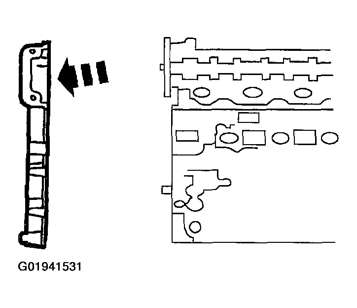
- Remove both timing chain guides.
- Remove the bolts.
- Remove both timing chain guides.
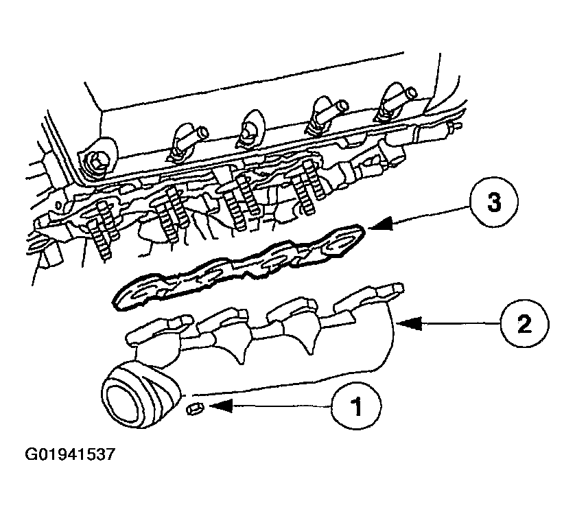
- Remove the RH exhaust manifold.
- Remove the nuts.
- Remove the RH exhaust manifold.
- Remove the RH exhaust manifold gasket.
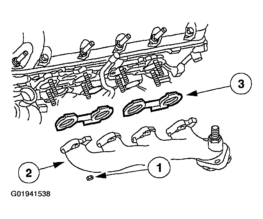
- Remove the LH exhaust manifold.
- Remove the nuts.
- Remove the LH exhaust manifold.
- Remove the LH exhaust manifold gaskets.
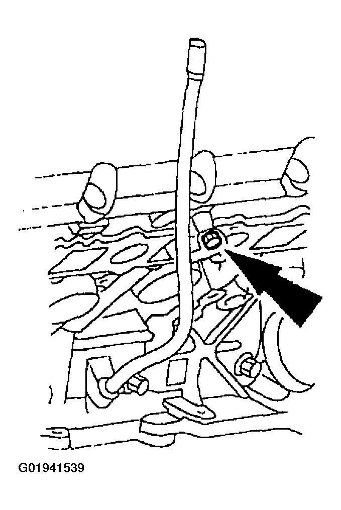
- Remove the bolt and the oil level indicator tube.
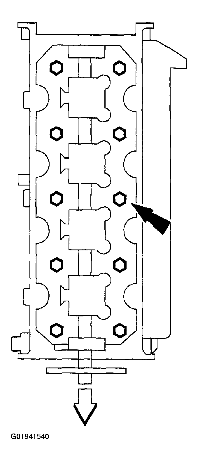
- Remove the bolts and discard.
- Remove the cylinder head.
- Discard the head gasket and clean the engine block surface.
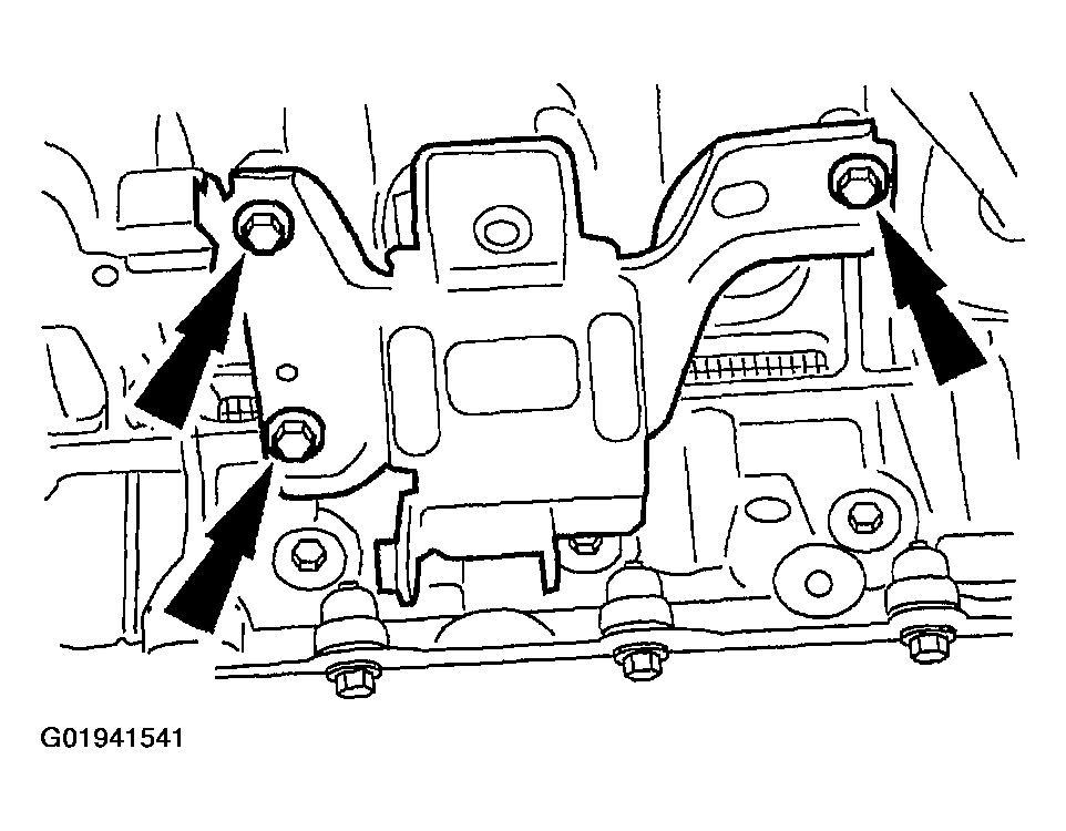
- Remove the bolts, and remove the LH engine mount.
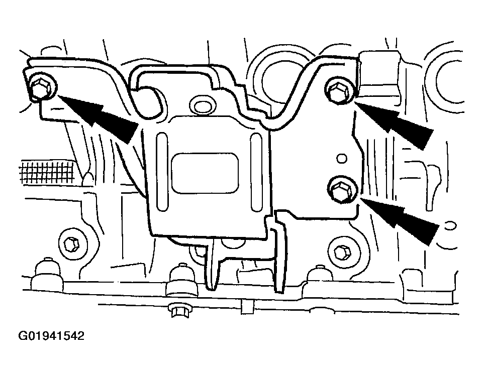
- Remove the bolts, and remove the engine mount.
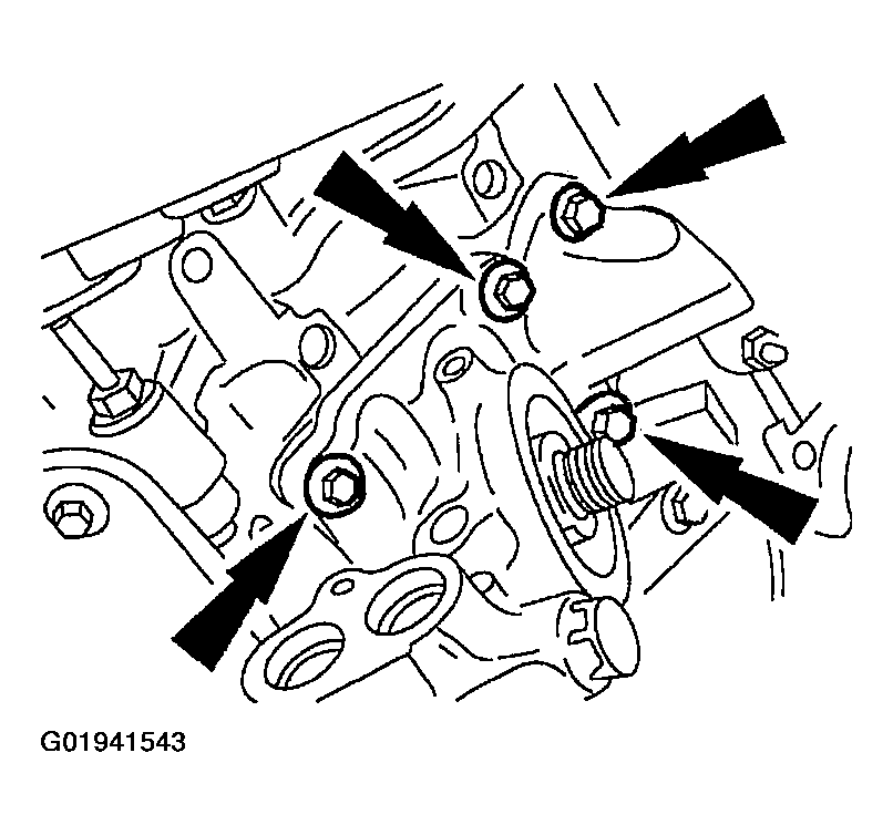
- Remove the bolts retaining the oil filter adapter and oil filter adapter gasket to the cylinder block.
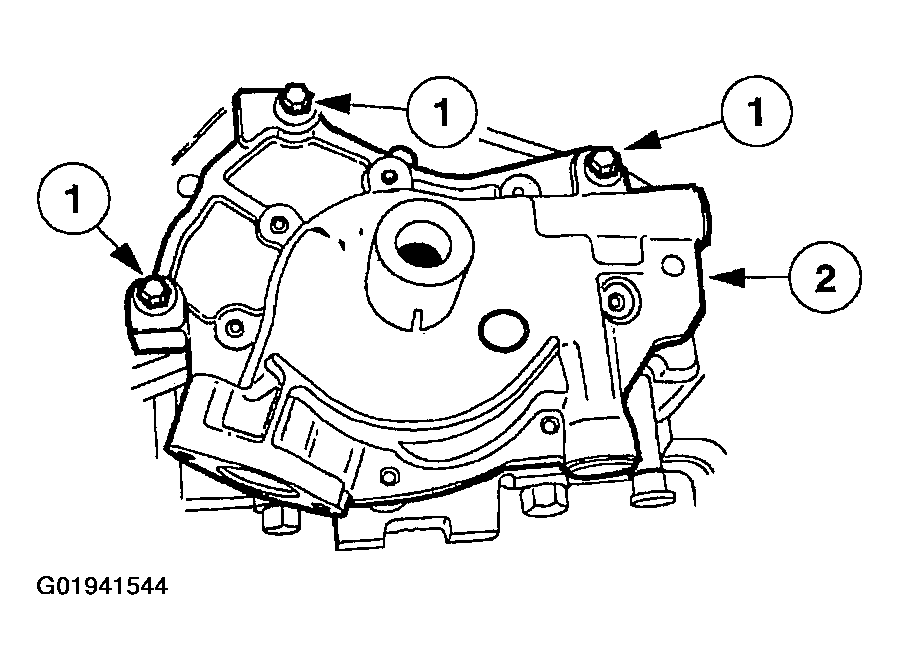
- Remove the oil pump.
- Remove the bolts.
- Remove the oil pump.
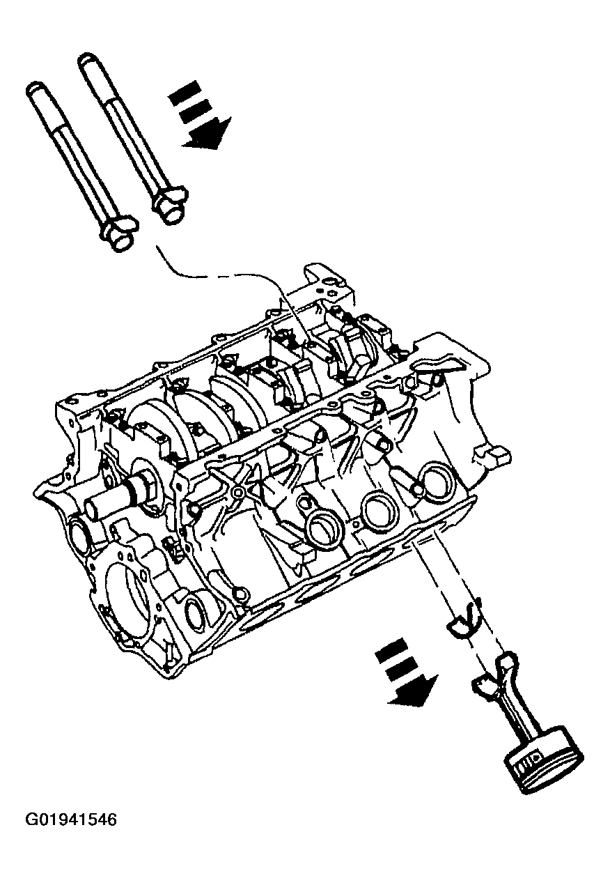
- Remove the bolts and the connecting rod caps. Discard the bolts.
- Use the Connecting Rod Guide Tool to push the piston through the top of the cylinder block.
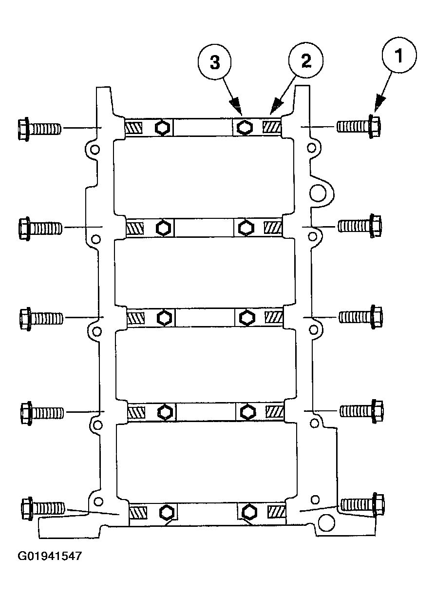
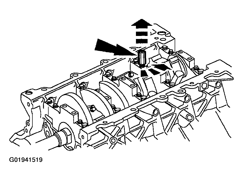
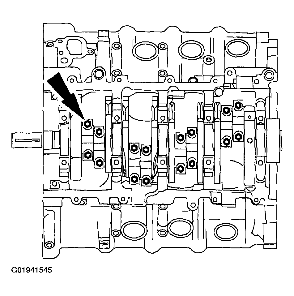
- Remove the crankshaft bearing cap fasteners.
- Remove and discard the cross-mounted main cap bolts.
- Loosen the jack screws.
- Remove and discard the main cap bolts.
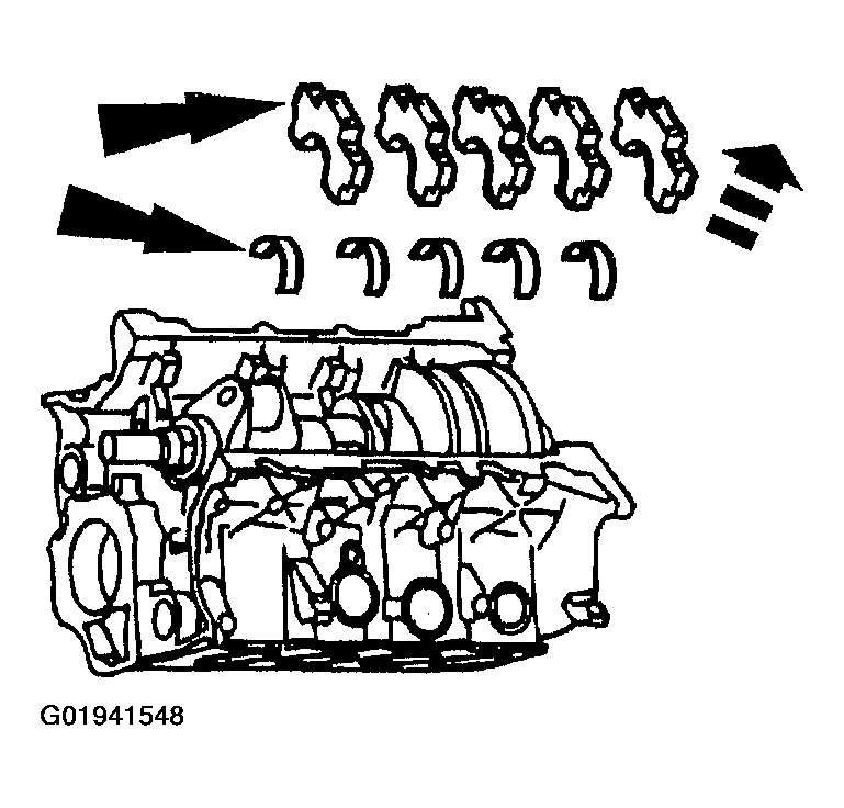
- Remove the five main bearing caps and the lower crankshaft main bearings.
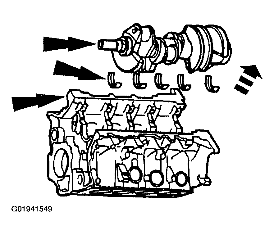
- Remove the crankshaft and the upper crankshaft main bearings from the cylinder block.
NOTE:
Correct fastener location is essential for the assembly procedure. Record fastener location.
CAUTION:
Unless otherwise instructed, at no time when the timing chains are removed and the cylinder heads are installed is the crankshaft or camshaft to be rotated. Severe piston and valve damage will occur.
CAUTION:
Unless otherwise instructed, at no time when the timing chains are removed and the cylinders heads are installed is the crankshaft or camshaft to be rotated. Severe piston and valve damage will occur.
CAUTION:
Install new cylinder head bolts. They are tighten-to-yield designed and cannot be reused.
CAUTION:
Place cylinder head on a cardboard or wood surface to prevent damage to the joint face.
NOTE:
RH shown; LH similar.
CAUTION:
Inspect the oil pump housing and gears for wear, scoring or grooves. Inspect gears for nicks, burrs or score marks. Remove minor imperfections with an oil stone. If necessary, install a new oil pump. If metal contamination is found in the oil pump, install a new oil cooler, if equipped.
CAUTION:
Verify that the connecting rods and rod caps have orientation numbers cast into them. If not, number the connecting rods and rod caps for correct orientation.
CAUTION:
Do not scratch the cylinder walls or crankshaft journals with the connecting rod.