LEMON Manuals: Even more car manuals for everyone: 1960-2025
Home >> Ford >> 2002 >> Crown Victoria Base, 4.6 9 >> Repair and Diagnosis (Single Page) >> Engine Mechanical >> Mechanical >> Engine - 4.6L >> Disassembly & Assembly Of Subassemblies >> Cylinder Head >> Assembly

Cylinder Head: Assembly

    NOTE: Do not use metal scrapers or other tools to clean the cylinder head.
  1. Use a plastic scraper and solvent to clean the cylinder head.
    • Use Metal Surface Cleaner F4AZ-19A536-RA or equivalent meeting Ford specification WSE-M5B392-A.
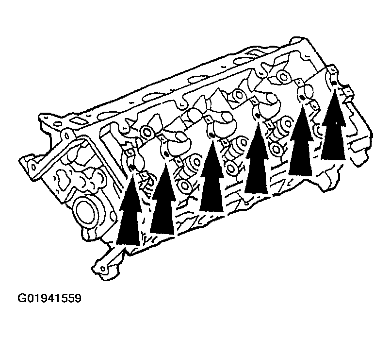
  2. Lubricate the camshaft journals with clean engine oil.
    Fig 1: Identifying Camshaft Journals
    G01941559Courtesy of FORD MOTOR CO.
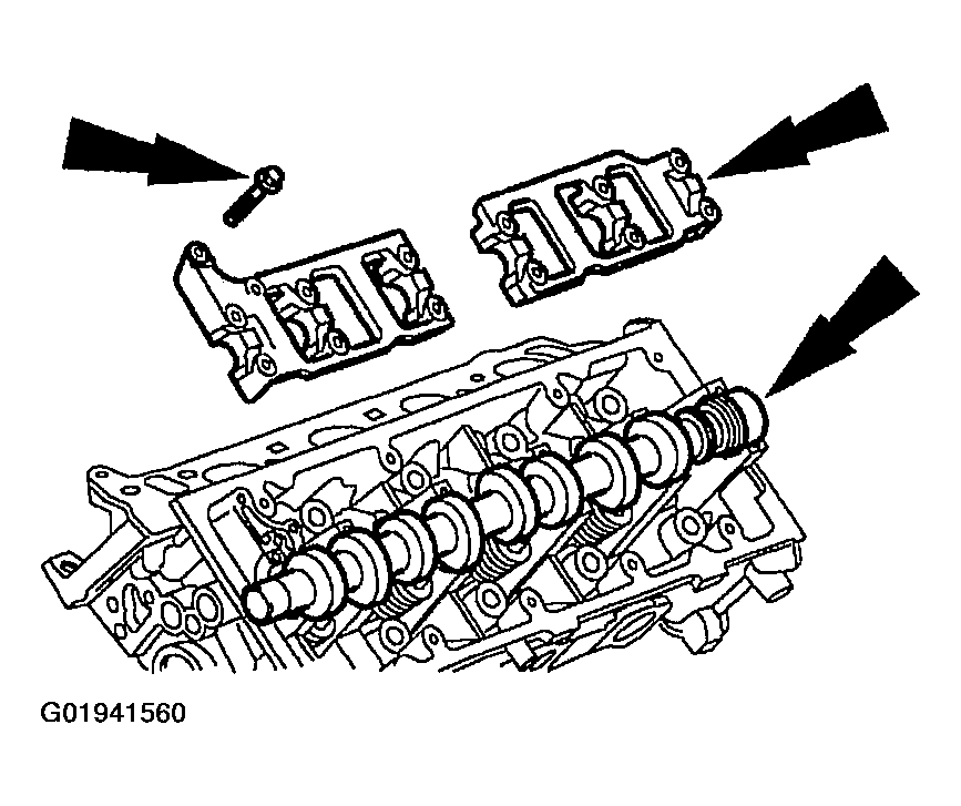
  3. Install the camshaft and the camshaft bearing caps.
    • Lubricate with clean engine oil and position the camshaft bearing caps.
    • Install the bolts loosely.
    Fig 2: Identifying Camshaft, Camshaft Bearing Caps & Bolts
    G01941560Courtesy of FORD MOTOR CO.
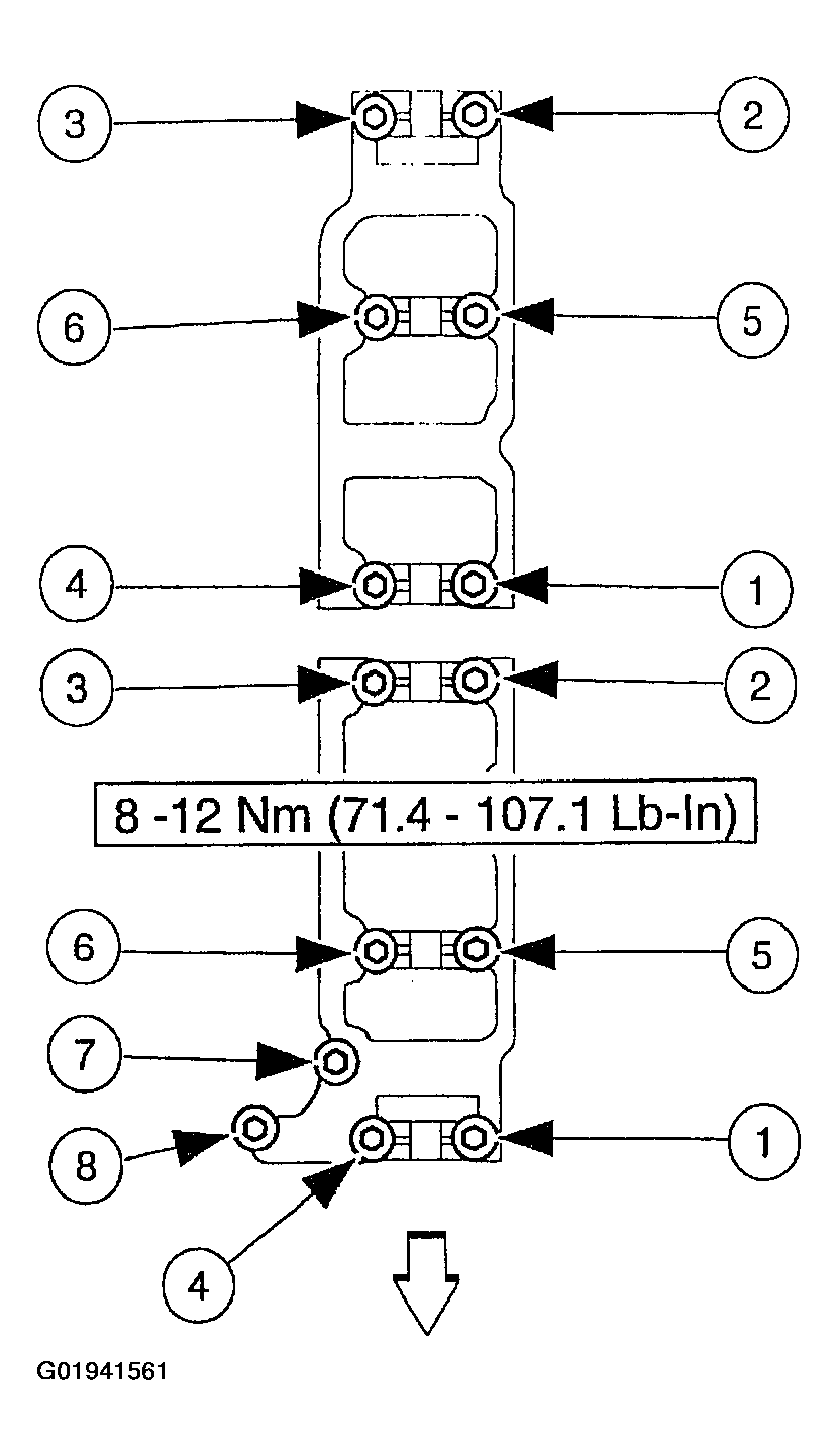
  4. Tighten the bolts in the sequence shown.
    Fig 3: Identifying Camshaft Bearing Cap Bolt Tightening Sequence
    G01941561Courtesy of FORD MOTOR CO.
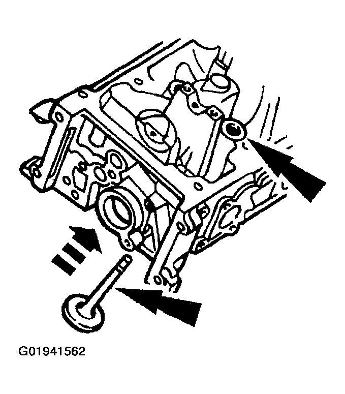
  5. Install the valves in the valve guides located in the cylinder head.
    Fig 4: Identifying Valve Guide & Valve
    G01941562Courtesy of FORD MOTOR CO.
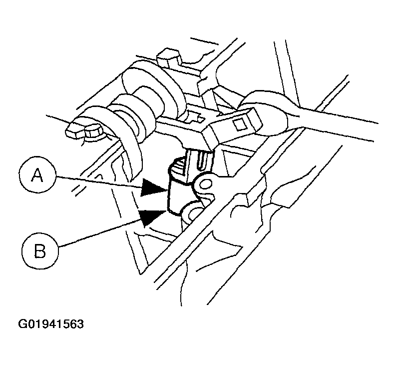
  6. Use the (A) Valve Stem Seal Replacer to install the (B) valve stem seals.
    Fig 5: Identifying Valve Stem Seal Replacer & Valve Stem Seal
    G01941563Courtesy of FORD MOTOR CO.
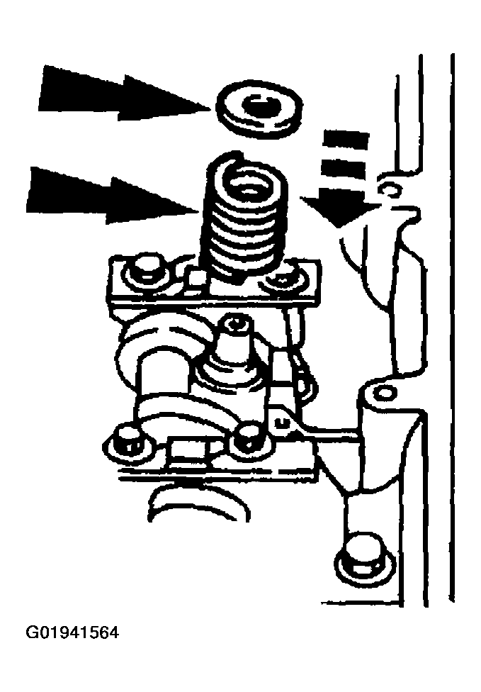
  7. Install the valve springs and the valve spring retainers onto the valves.
    Fig 6: Identifying Valve Spring & Valve Spring Retainer
    G01941564Courtesy of FORD MOTOR CO.
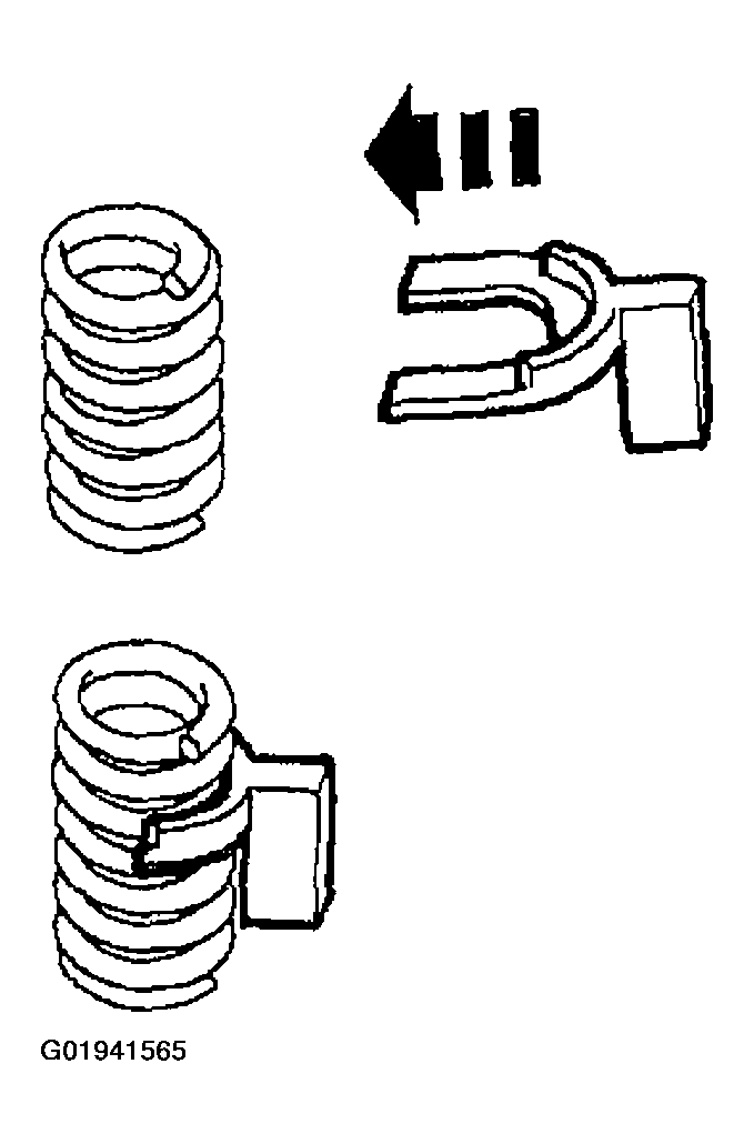
  8. Install the Valve Spring Spacer between the valve spring coils to prevent valve stem seal damage.
    Fig 7: Installing Valve Spring Spacer Between Valve Spring Coils
    G01941565Courtesy of FORD MOTOR CO.
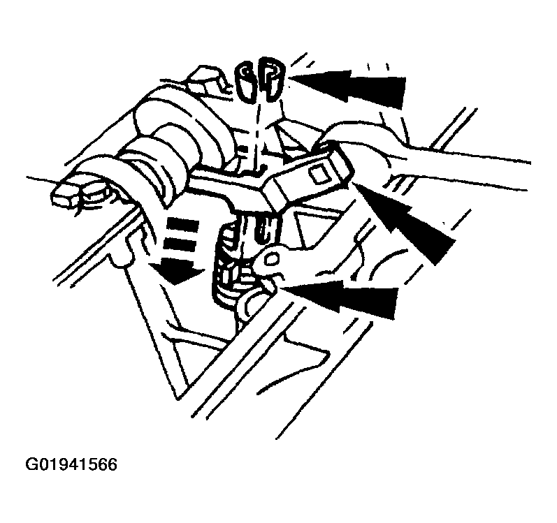
  9. Use the Valve Spring Compressor to compress the valve springs, and install the valve spring retainer keys.
    Fig 8: Identifying Valve Spring Compressor, Valve Springs & Valve Spring Retainer Keys
    G01941566Courtesy of FORD MOTOR CO.
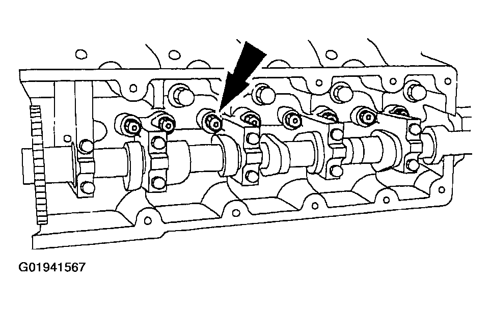
  10. Install the hydraulic lash adjusters in their original locations.
    Fig 9: Identifying Hydraulic Lash Adjusters
    G01941567Courtesy of FORD MOTOR CO.
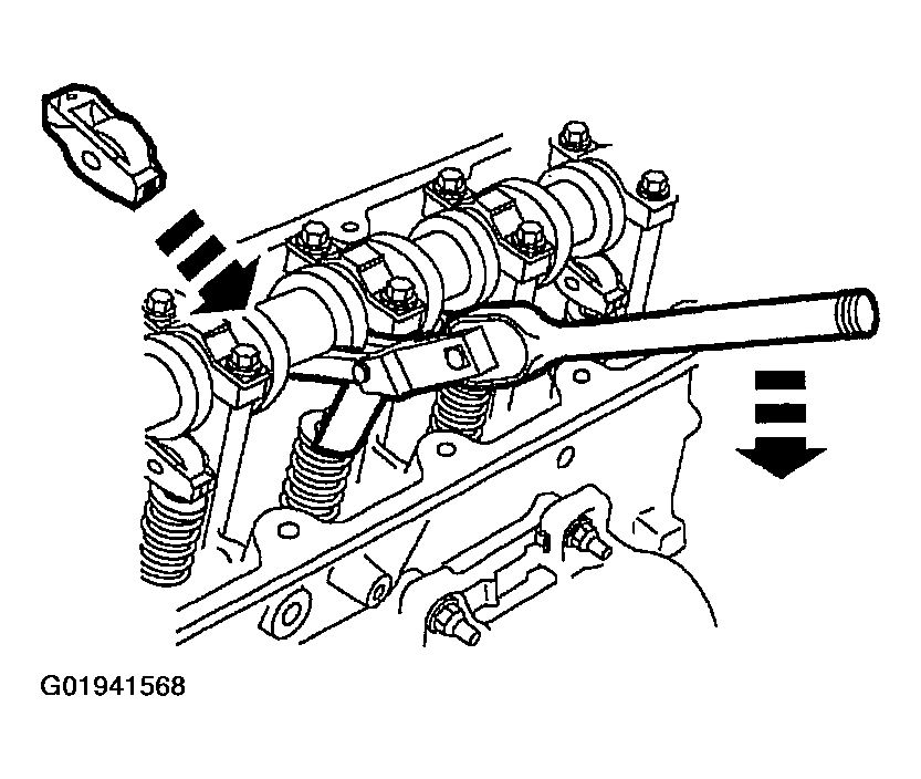
  11. Install the roller followers in their original locations.
    Fig 10: Installing Roller Followers
    G01941568Courtesy of FORD MOTOR CO.
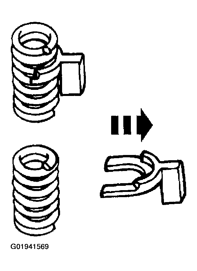
  12. Remove the Valve Spring Spacer.
    Fig 11: Removing Valve Spring Spacer
    G01941569Courtesy of FORD MOTOR CO.