Engine - 4.6L: Assembly: Engine: Assembly
All Engines
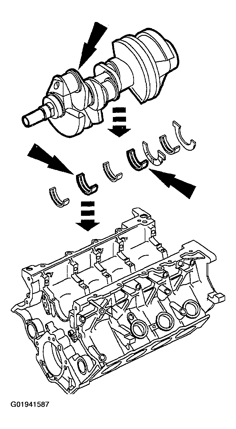
- Lubricate with clean engine oil and install the crankshaft upper main bearings into the cylinder block.
- Install the crankshaft onto the upper crankshaft thrust bearing and main bearings.
- Install the rear main bearing cap.
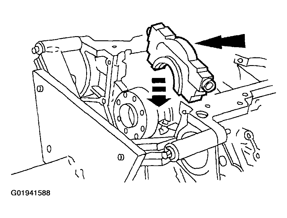
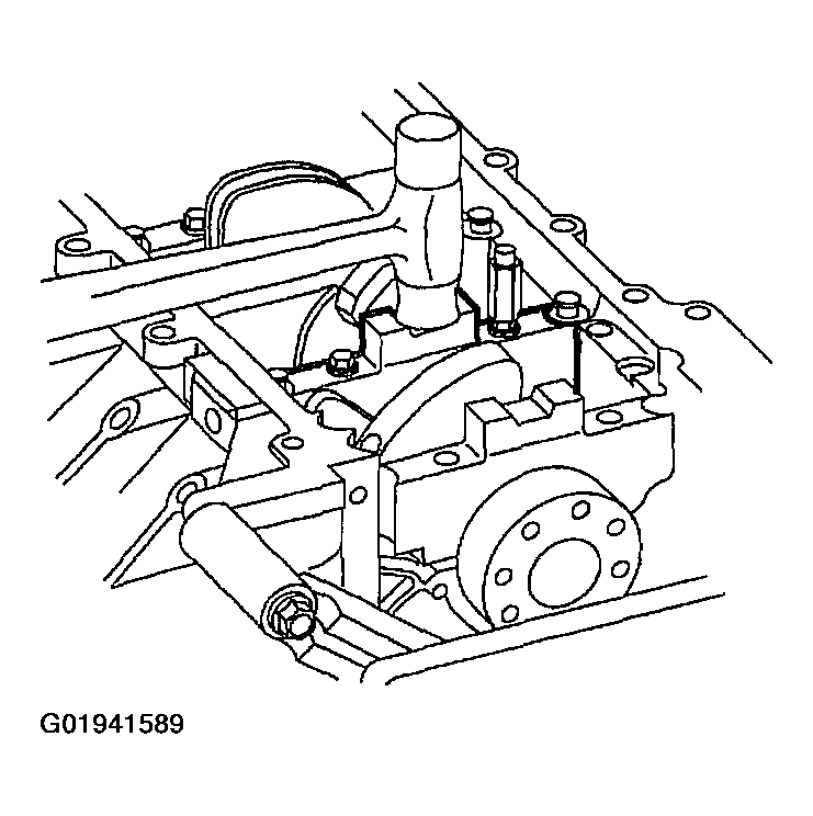
- Install the crankshaft lower main bearings, thrust bearing and thrust washer into the main bearing caps. Locate the main bearing cap on the cylinder block and tap into place using a plastic or dead-blow hammer.
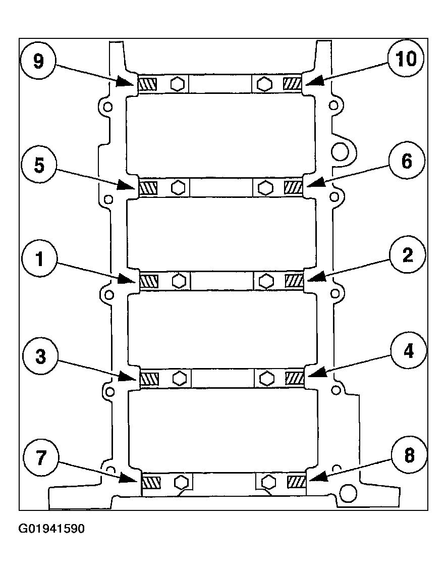
- Back out the jack screws against the cylinder block in two stages, in the sequence shown.
- Stage 1: Tighten to 5 N.m (44.6 lb-in).
- Stage 2: Tighten to 9-11 N.m (80-97 lb-in).
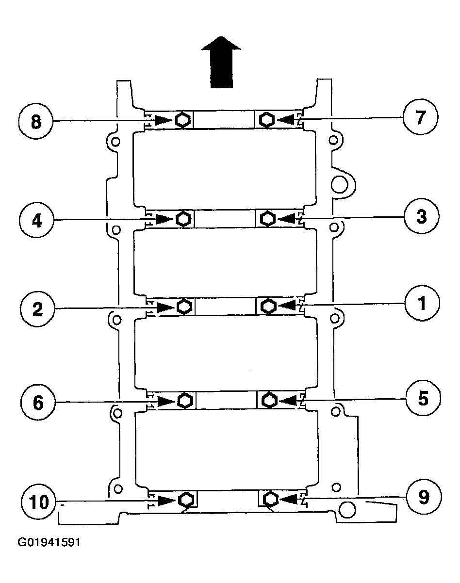
- Install and tighten the bolts in two stages.
- Stage 1: Tighten to 40 N.m (30 lb-ft).
- Stage 2: Tighten an additional 90 degrees.
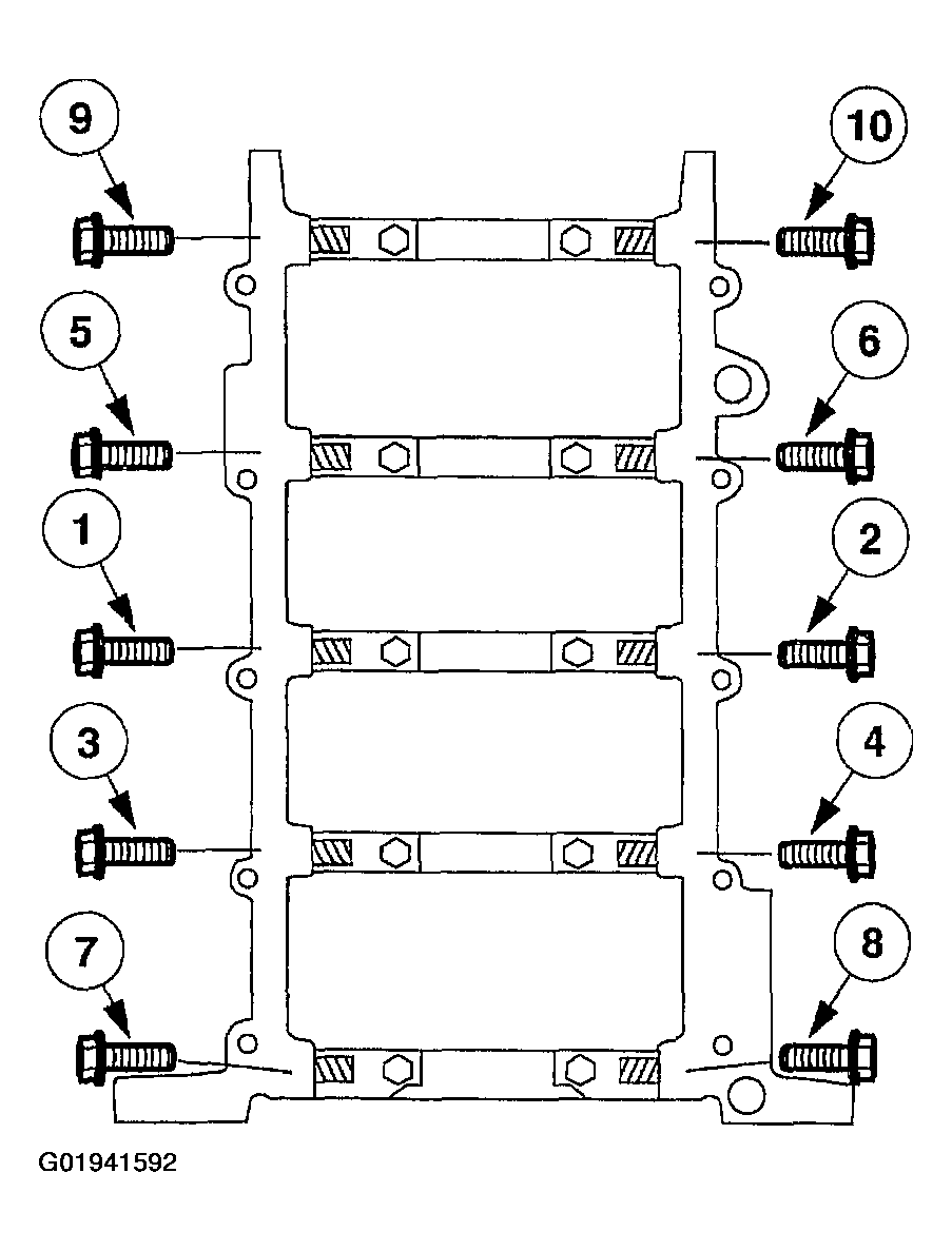
- Install the bolts and tighten in two stages in the sequence shown.
- Stage 1: Tighten to 10 N.m (89.2 lb-in).
- Stage 2: Tighten to 19-23 N.m (14-17 lb-ft).
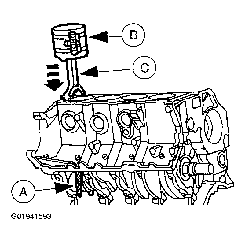
- Use the Connecting Rod Guide Tool (A) and the Piston Ring Compressor (B) to install the connecting rod (C) with upper connecting rod bearing in place.
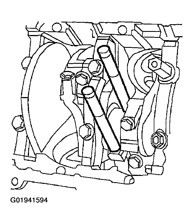
- Once the connecting rod is seated on the crankshaft journal, remove the Connecting Rod Guide Tool.
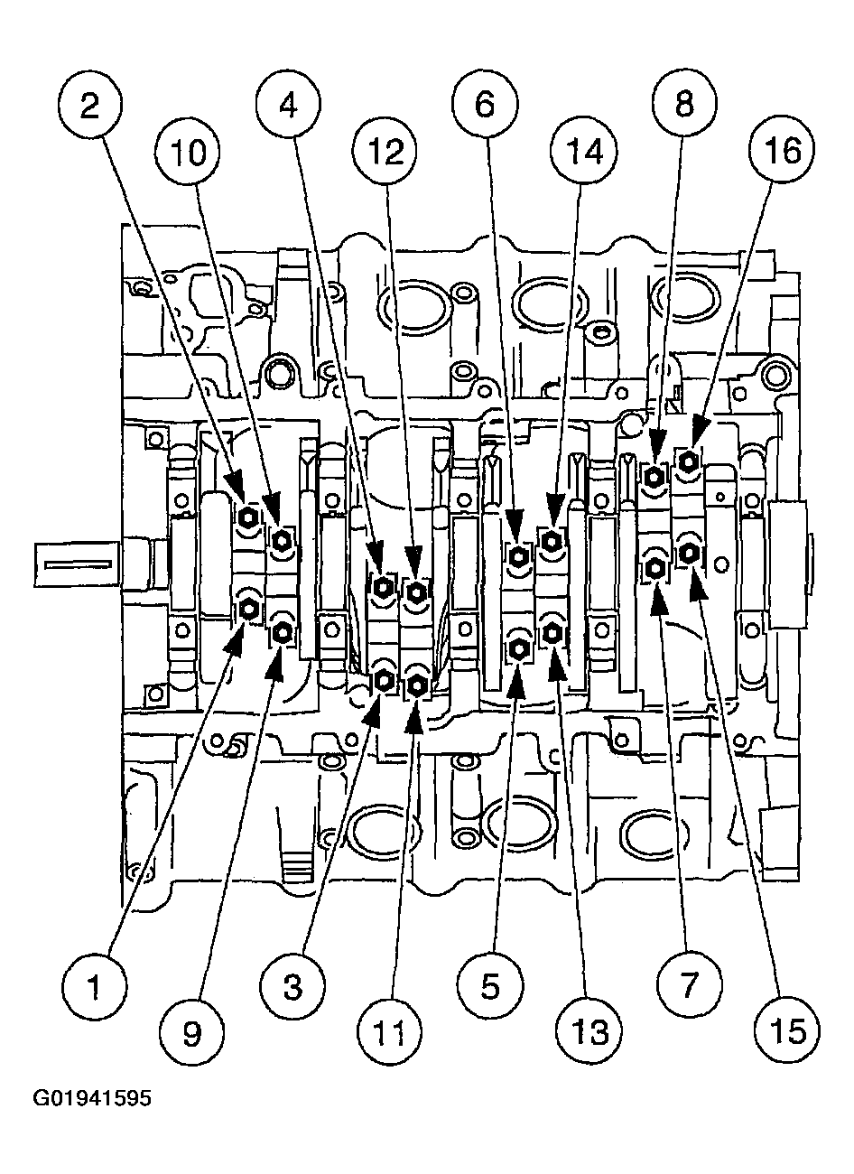
- Position the lower bearing and connecting rod, and install the new bolts loosely.
- Tighten the bolts in two stages, in the sequence shown.
- Stage 1: Tighten to 40-45 N.m (30-33 lb-ft).
- Stage 2: Rotate an additional 90-120 degrees.
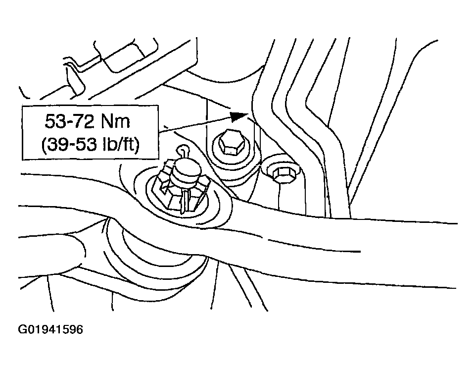
- Install the RH engine mount and the three bolts.
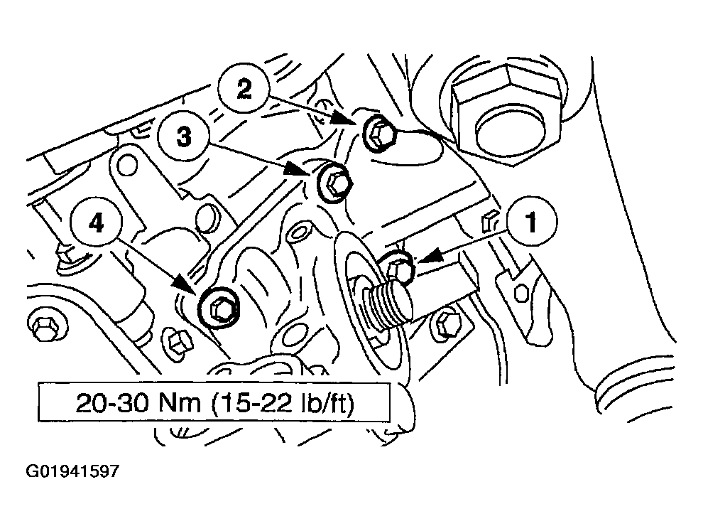
- Install the oil filter adapter and tighten in the sequence shown.
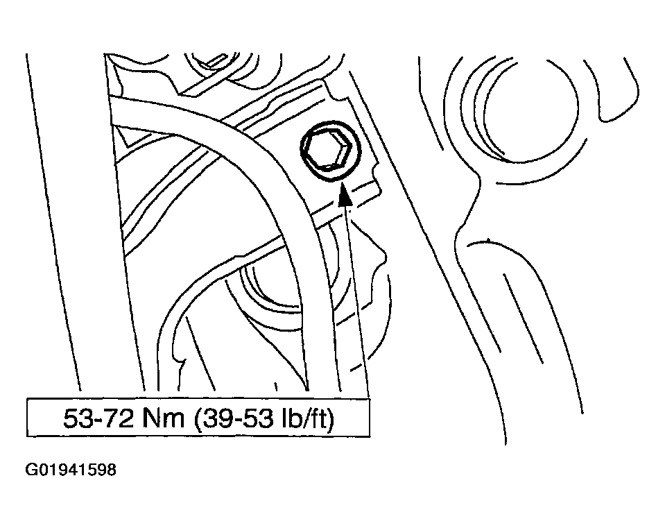
- Install the LH engine mount and the bolts.
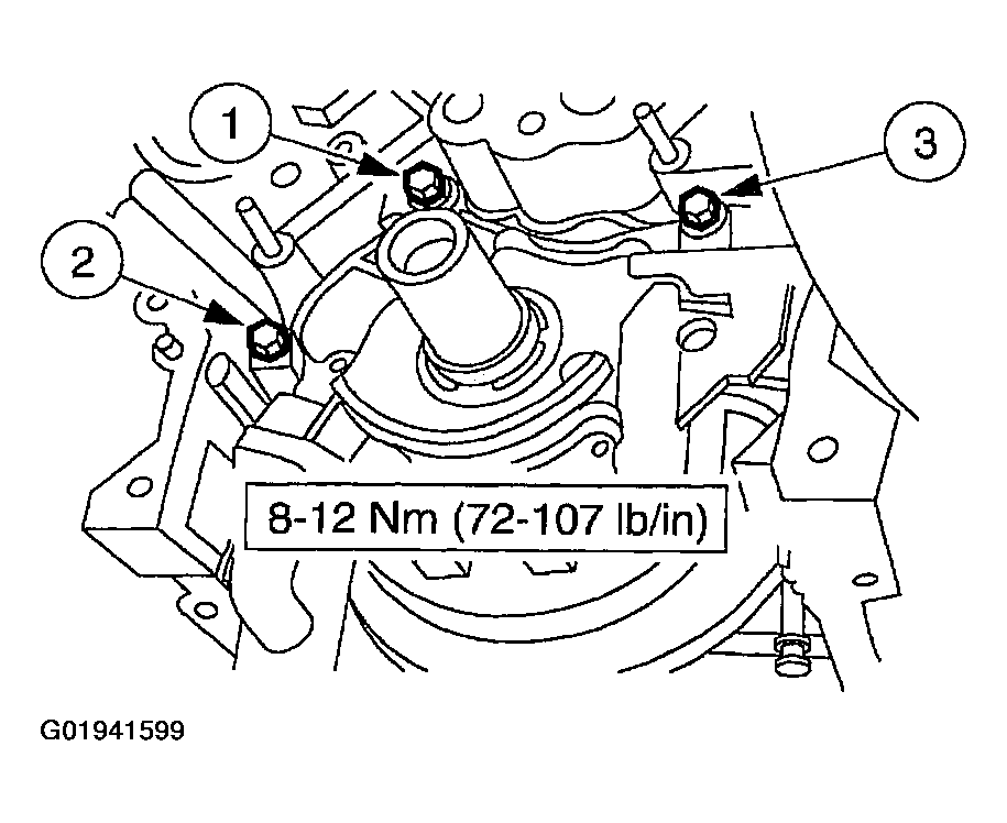
- Position the oil pump and install the bolts loosely.
Tighten the bolts in the sequence shown.
- Rotate inner rotor of oil pump to align with flats on crankshaft and install oil pump flush with cylinder block.
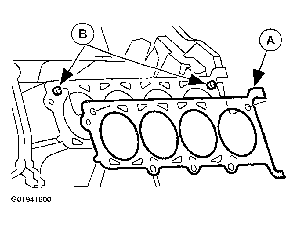
- Position the (A) head gasket over the (B) dowel pins.
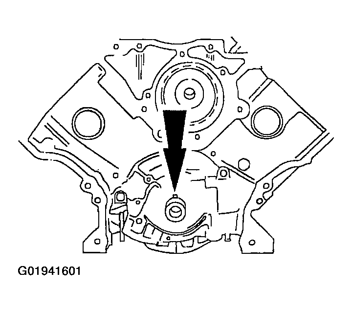
- Rotate the crankshaft until the crankshaft keyway points toward the top of the engine (12 o'clock).
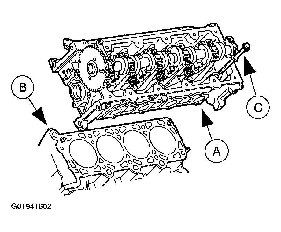
- Position the (A) cylinder head over the dowels on the (B) head gasket and install the (C) bolts loosely.
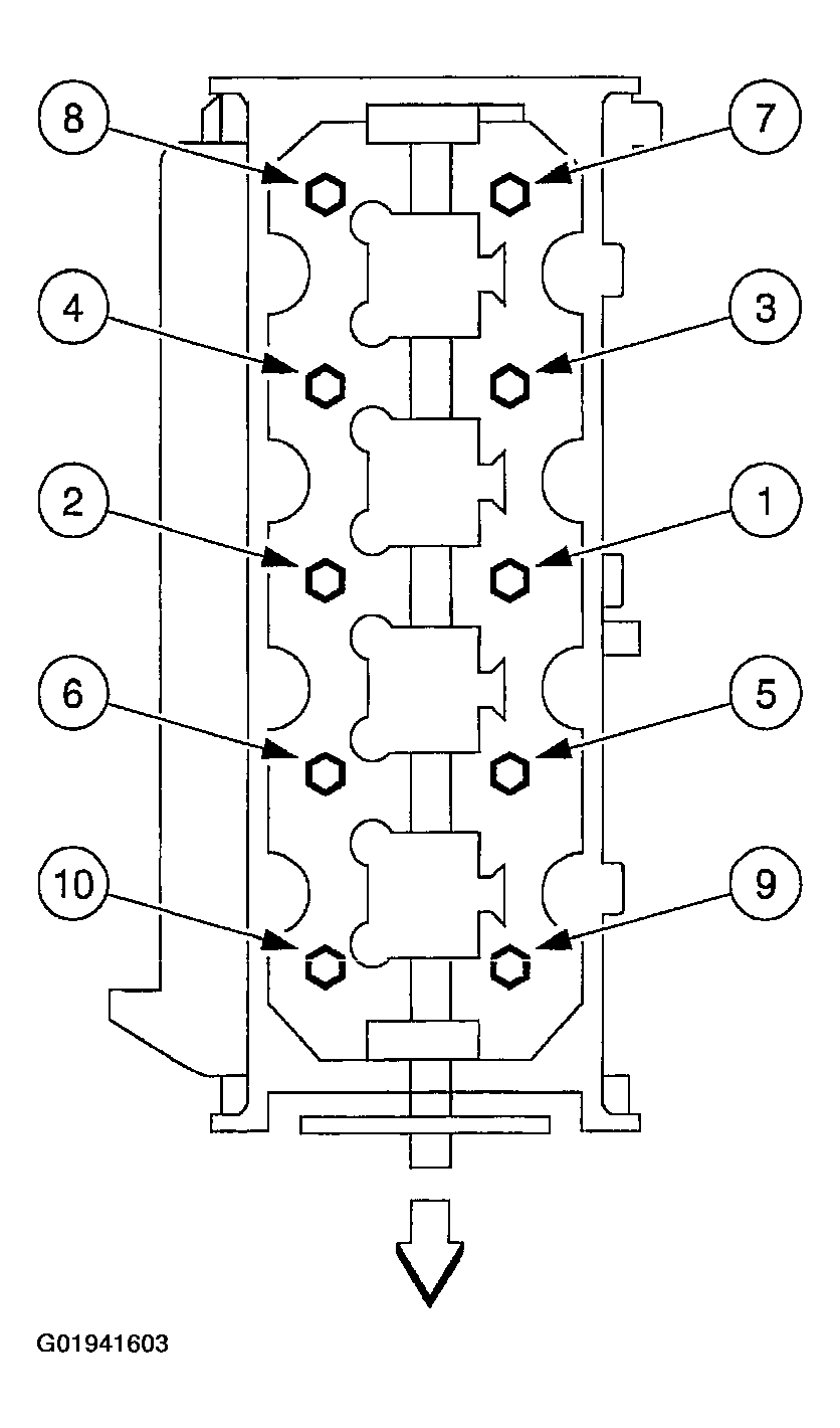
- Tighten the bolts in six steps, in the sequence shown.
- Step 1: Tighten to 37-43 N.m (28-31 Ib-ft).
- Step 2: Tighten an additional 85-95 degrees.
- Step 3: Loosen the bolts a minimum of one full turn (360 degrees).
- Step 4: Tighten to 37-43 N.m (28-31 lb-ft).
- Step 5: Tighten an additional 85-95 degrees.
- Step 6: Rotate an additional 85-95 degrees.
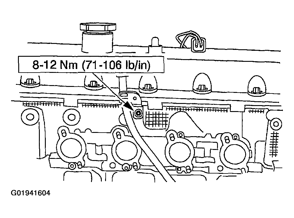
- Install the oil level indicator tube.
- Install a new O-ring seal on the oil level indicator tube.
- Install the oil level indicator tube.
- Install the bolt.
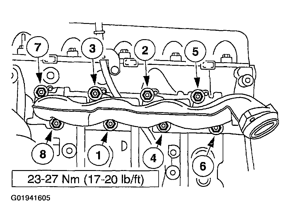
- Install the LH exhaust manifold.
- Install the exhaust manifold gasket.
- Install the exhaust manifold.
- Tighten the nuts in the sequence shown.
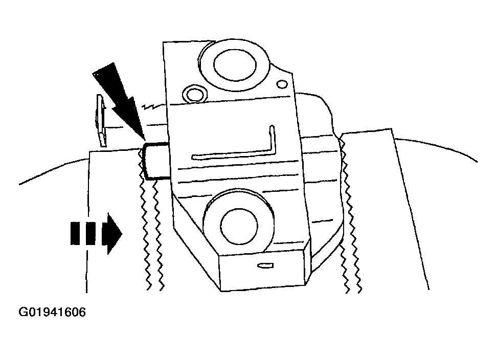
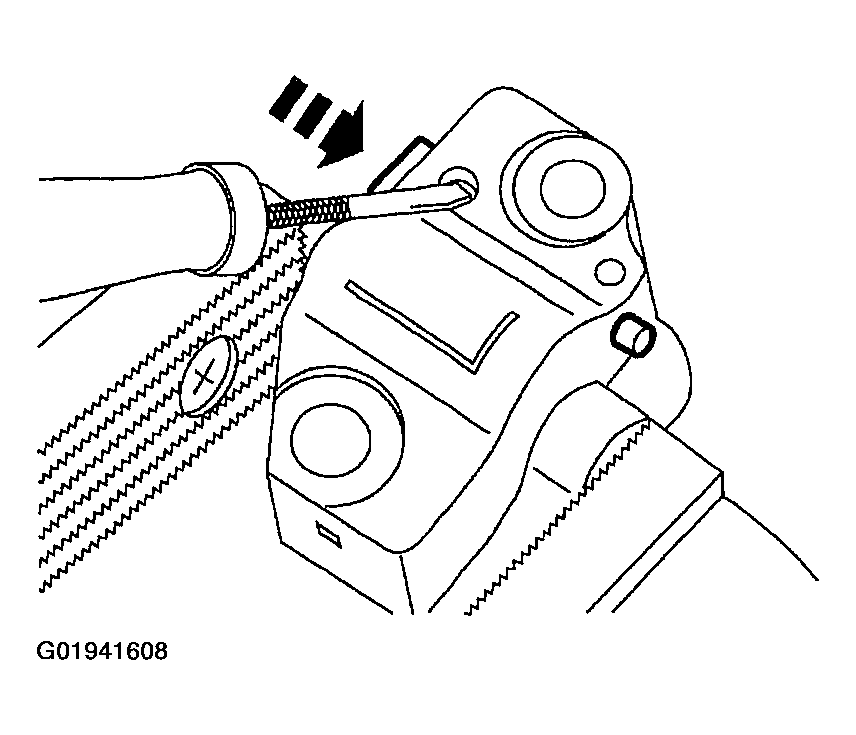
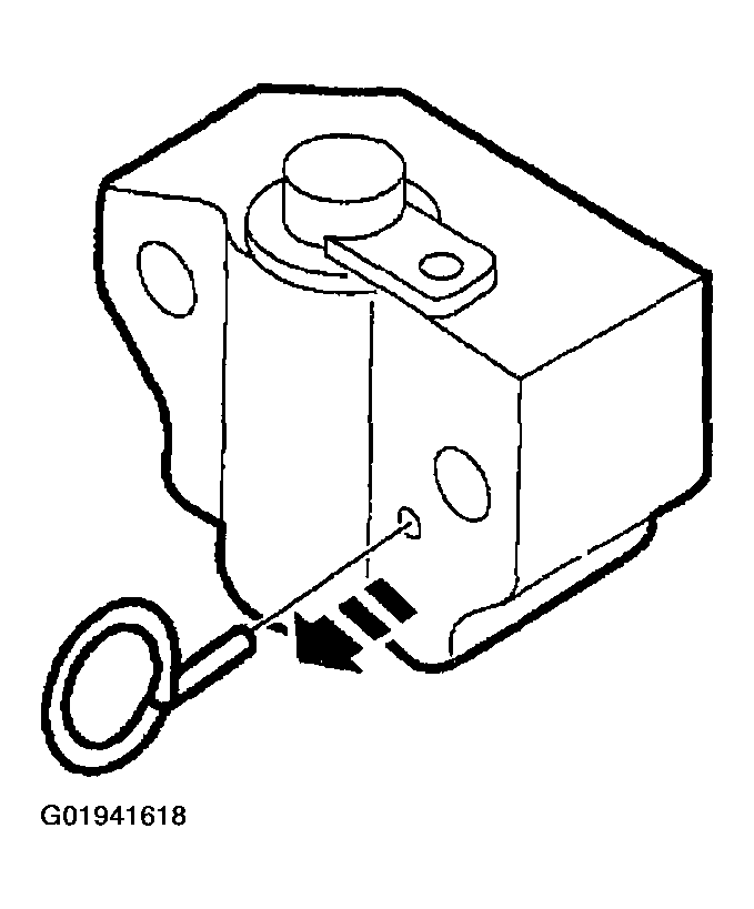
- Compress the tensioner plunger, using the edge of a vise.
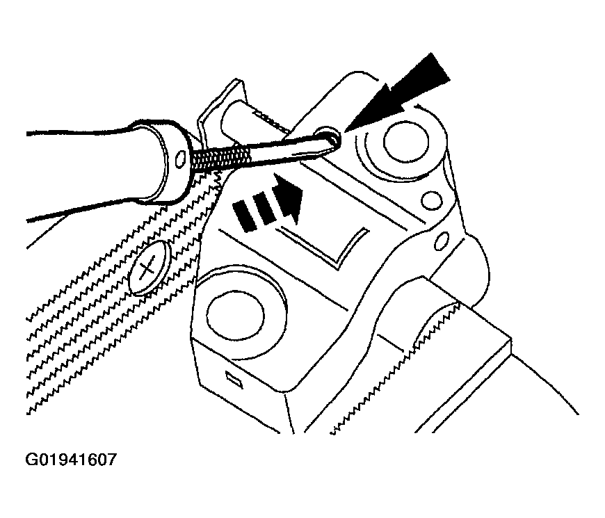
- Using a small screwdriver or pick, push back and hold the ratchet mechanism.
- While holding the ratchet mechanism, push the ratchet arm back into the tensioner housing.
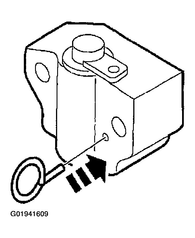
- Install a paper clip into the hole in the tensioner housing to hold in the ratchet assembly and plunger during installation.
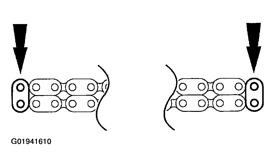
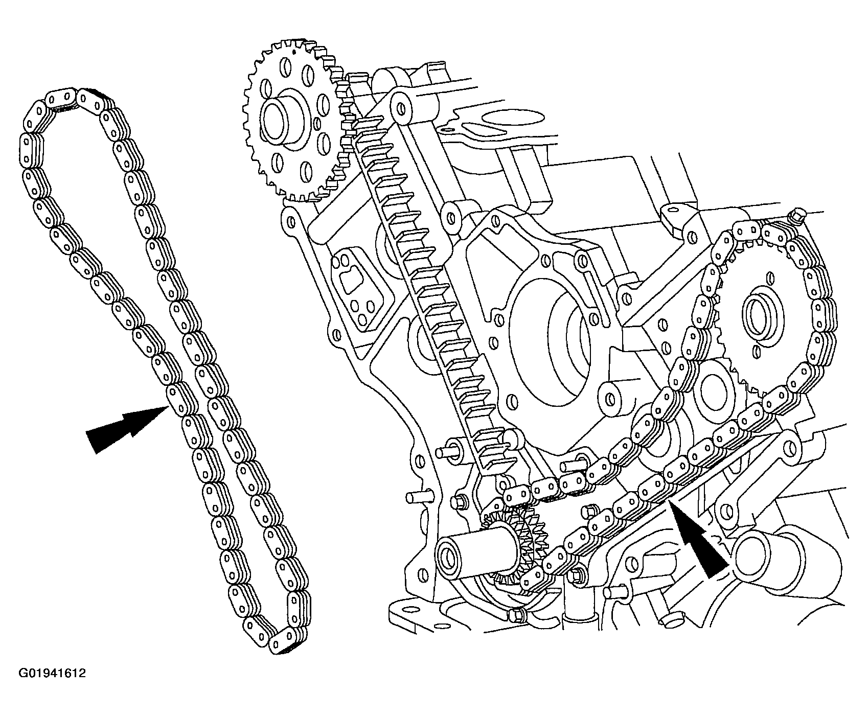
- If the copper links are not visible, mark one link on one end and one link on the other end, and use as timing marks.
- Remove the tensioner from the vise.
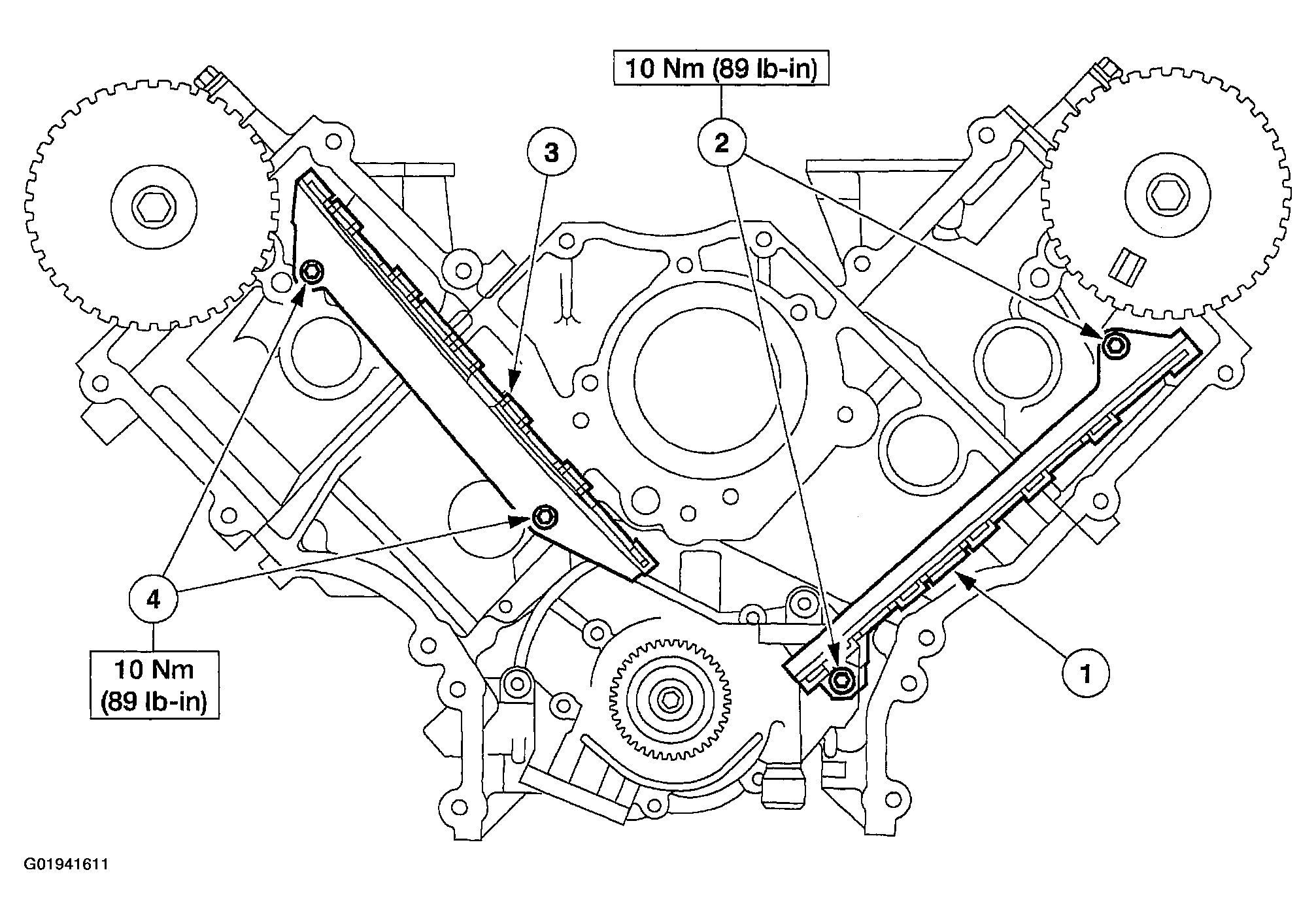
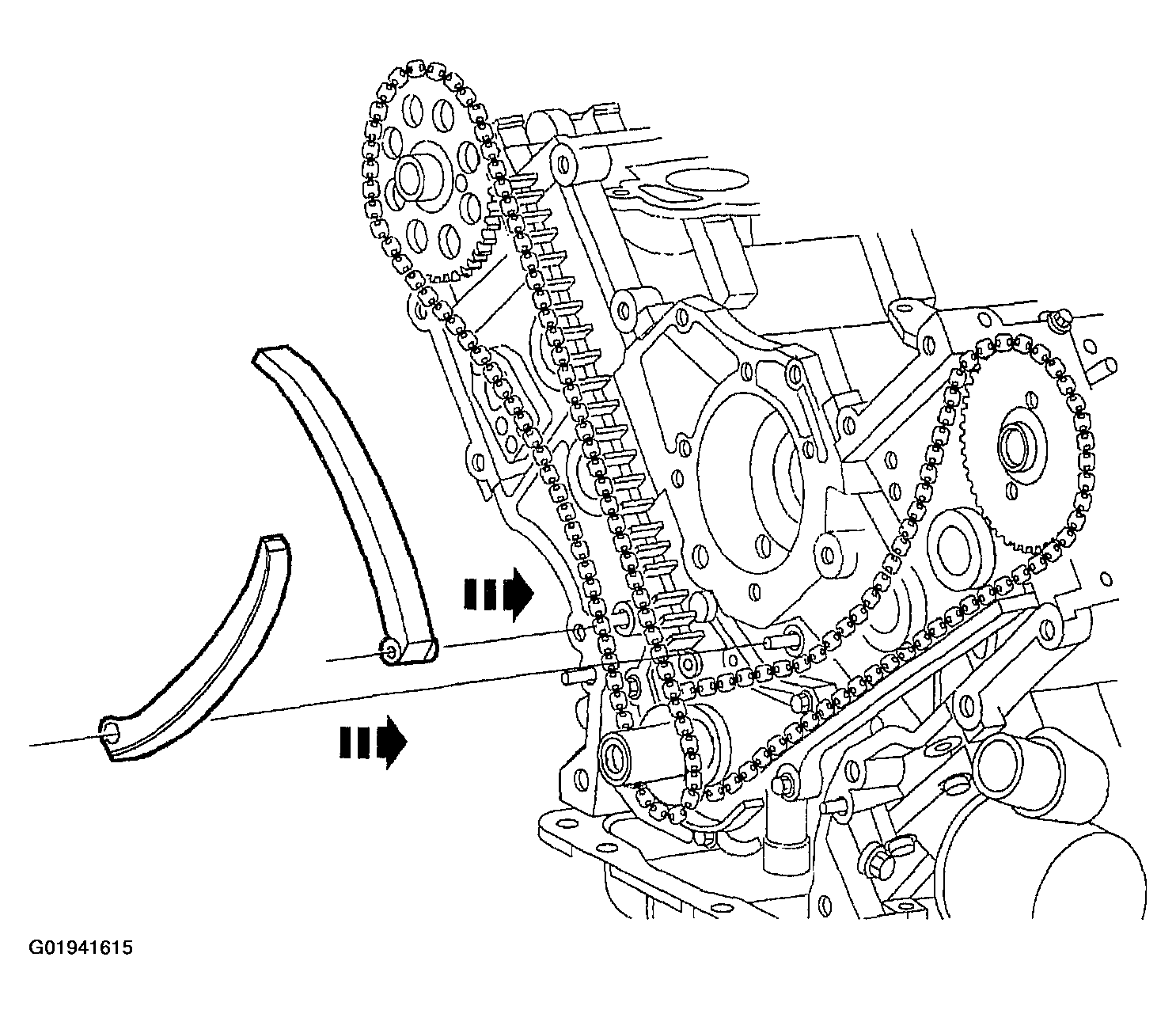
- Install the timing chain guides.
- Position the LH timing chain guide.
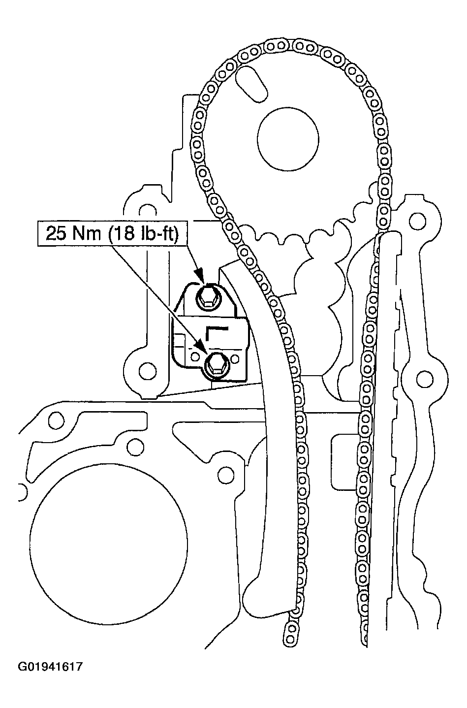
- Install and tighten the bolts.
- Position the RH timing chain guide.
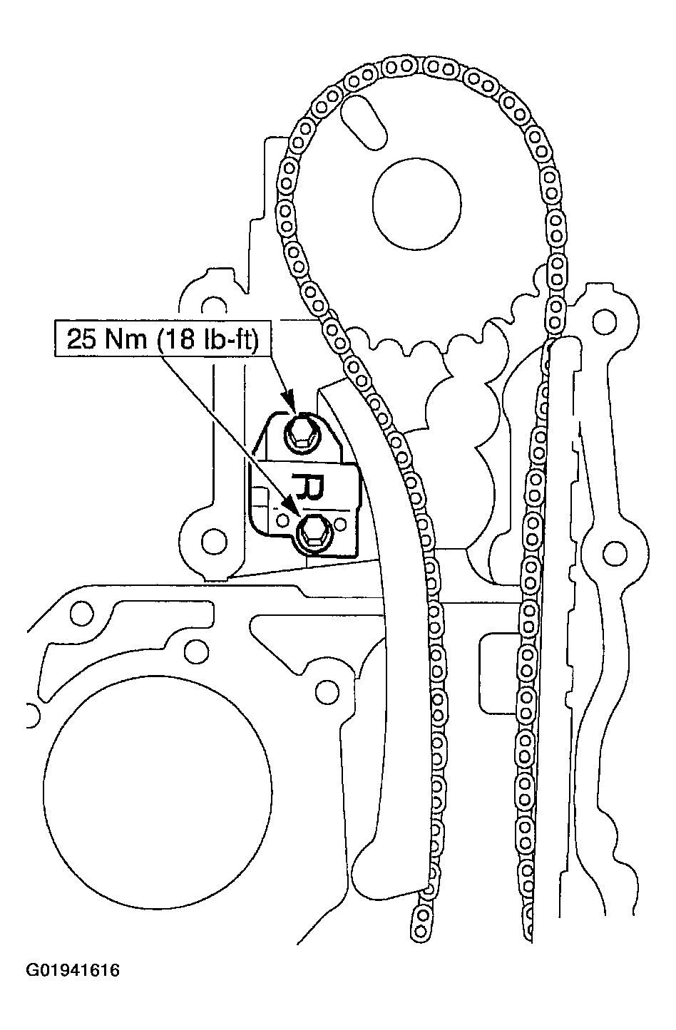
- Install and tighten the RH bolts.
- Install the timing chain and crankshaft sprocket.
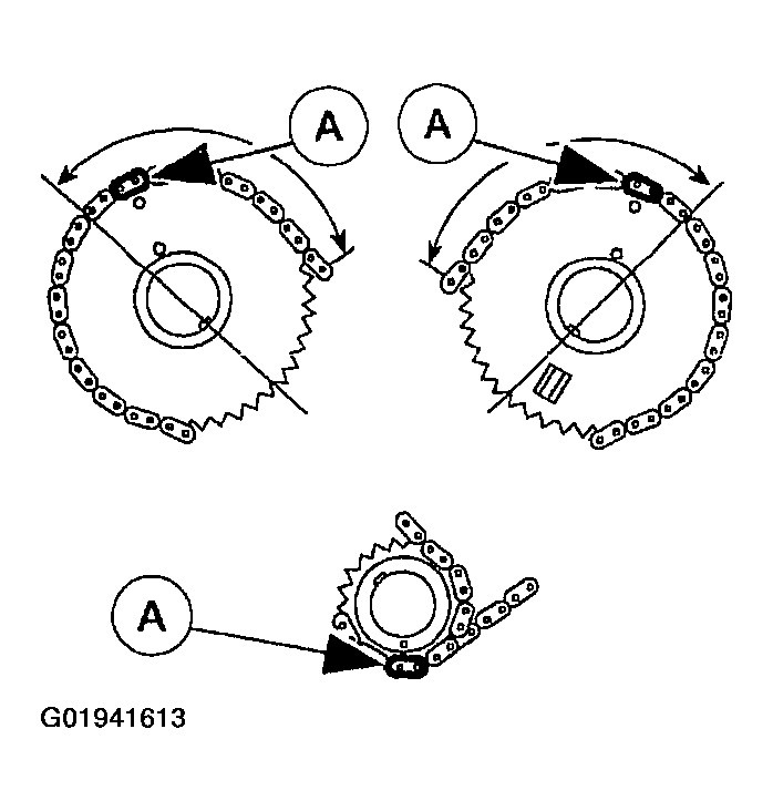
- Slide the crankshaft sprocket onto the crankshaft, aligning the copper link on the timing chains with the dot on the crankshaft sprocket.
- Position the timing chains over the camshaft sprocket, aligning the copper links with the dots on the camshaft sprockets.
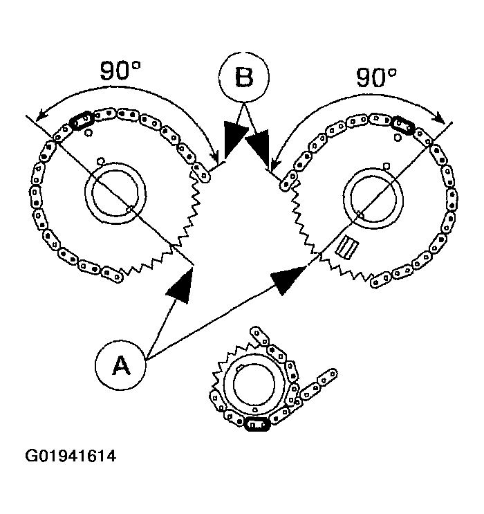
- Make sure that the (A) copper marks on the timing chains are lined up with the corresponding dots on the crankshaft sprockets and camshaft sprocket.
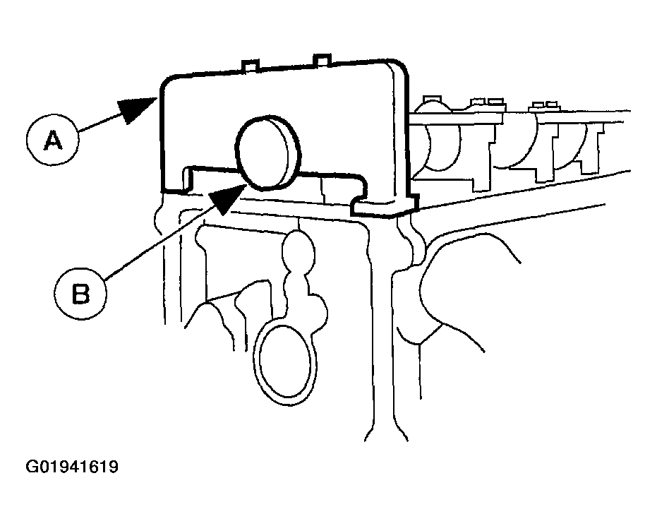
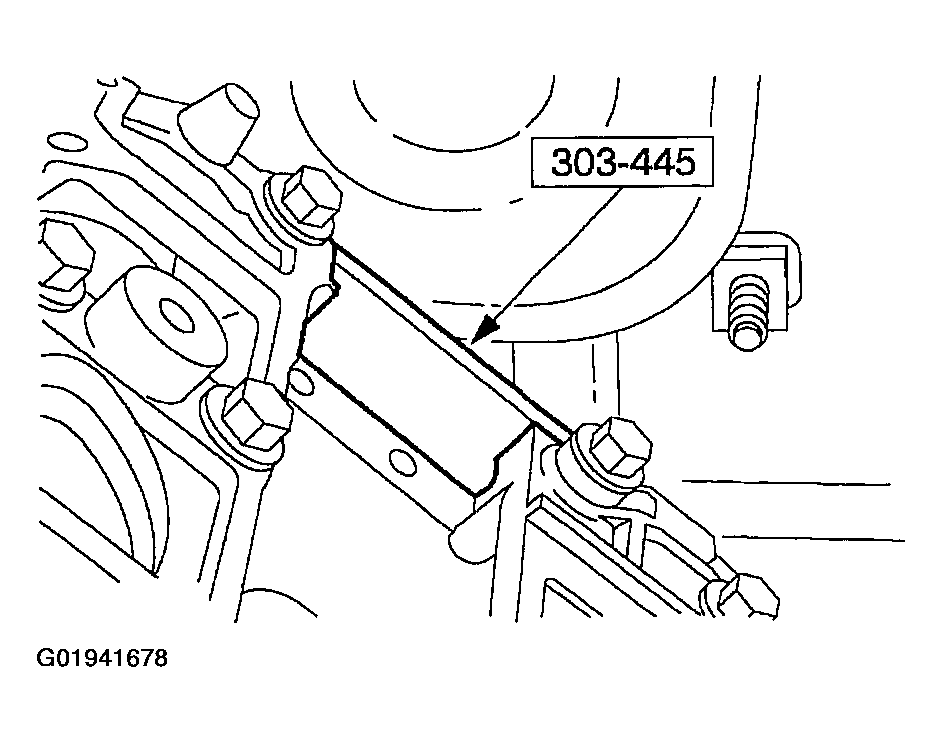
- Use the Camshaft Positioning Tool to make sure that the (A) camshaft sprocket keyway is 90 degrees from the (B) valve cover mounting surface.
- Position the LH and RH timing chain tensioner arm on the dowel pins.
- Position the RH timing chain tensioner and install the timing chain tensioner bolts.
- Position the LH timing chain tensioner and install the bolts.
- Remove both the paper clips from the timing chain tensioners.
- Remove the (A) Camshaft Positioning Tool and the Camshaft Positioning Tool Adapters from the (B) camshaft.
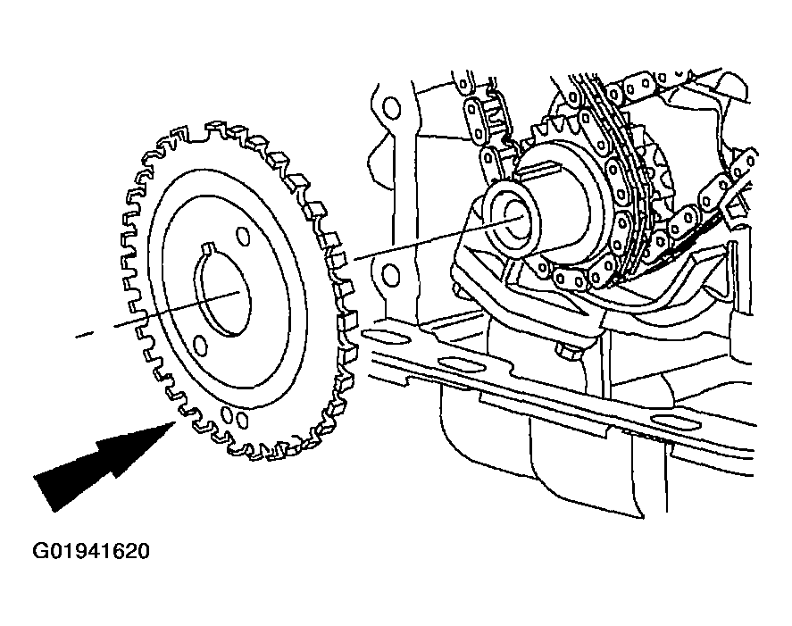
- Position the crankshaft sensor ring on the crankshaft.
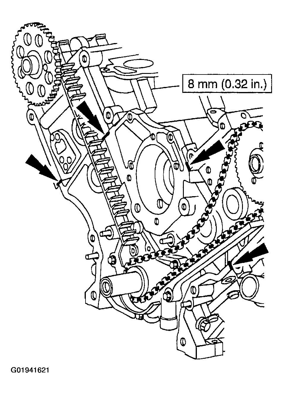
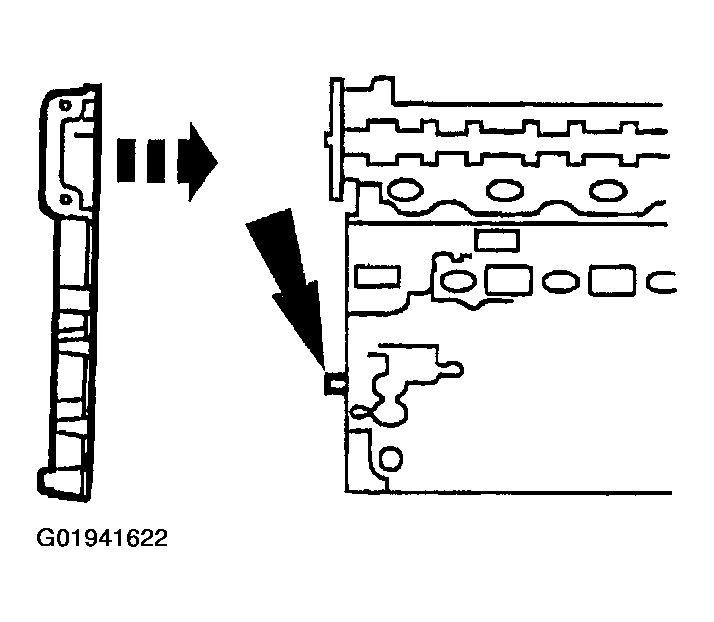
- Apply a bead of sealant along the head-to-block surface as shown.
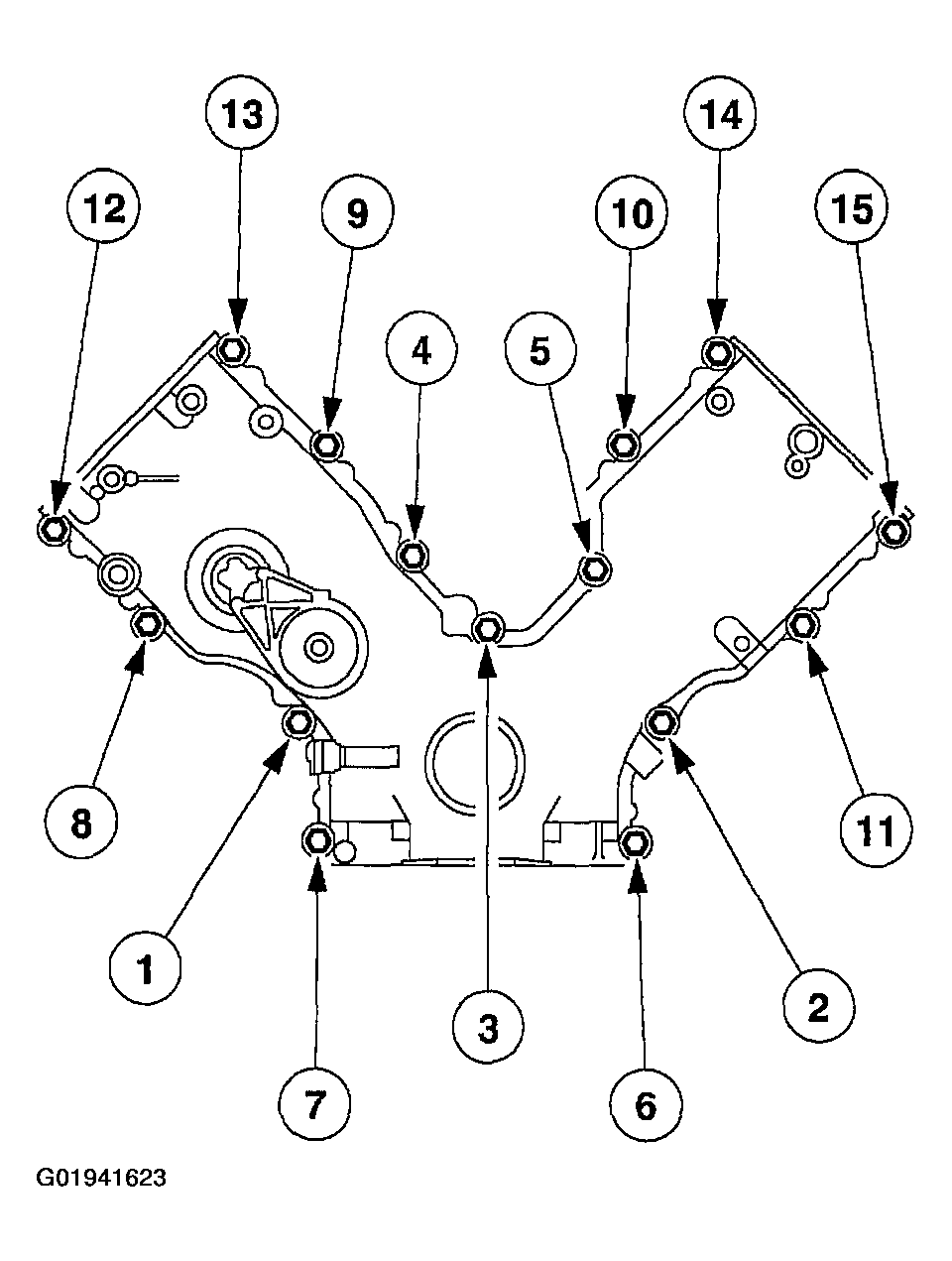
- Install a new engine front cover gasket on the engine front cover. Position the engine front cover. Install the fasteners finger-tight.
- Tighten the fasteners in two stages.
Stage 1: Tighten fasteners 1 through 7 to 25 N.m (18 lb-ft).
Stage 2: Tighten fasteners 6 through 15 to 40-55 N.m (30-41 lb-ft).
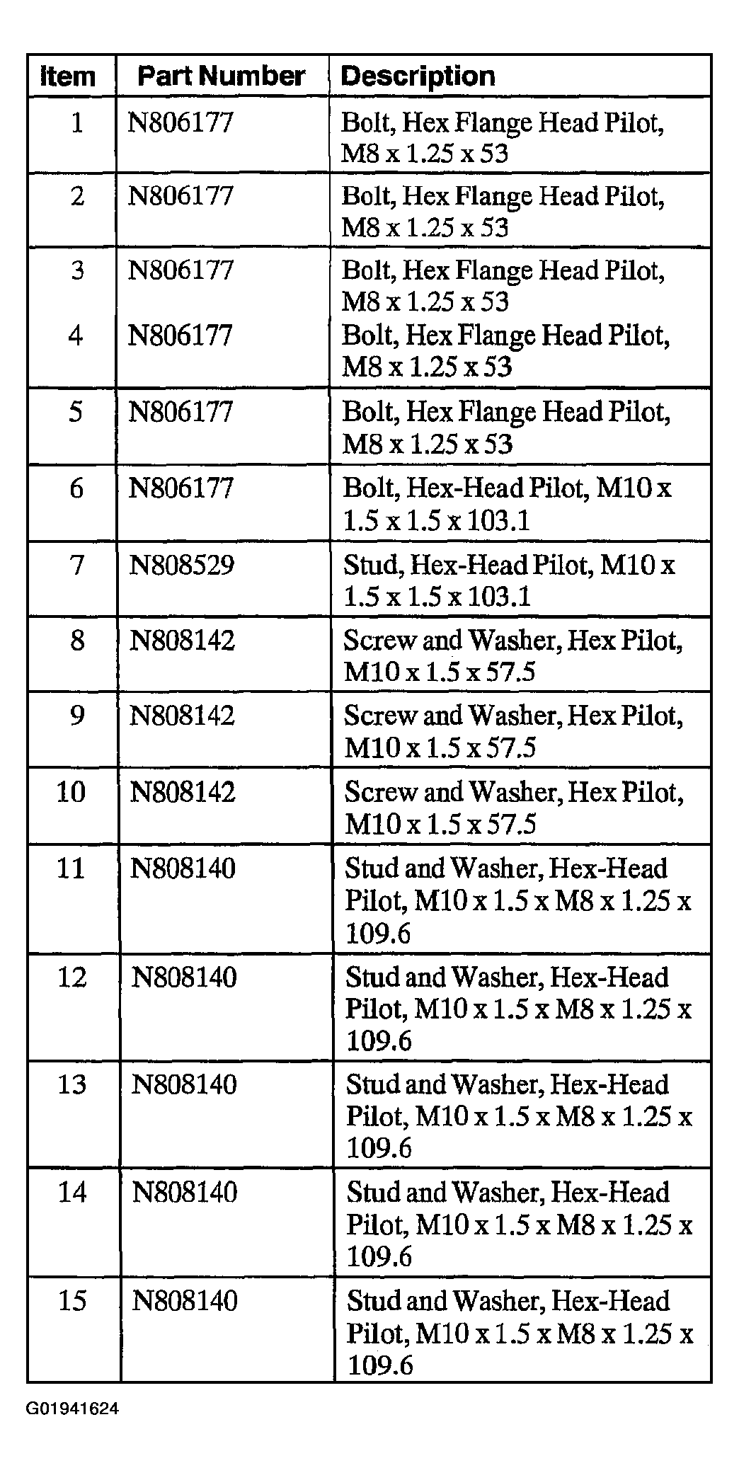
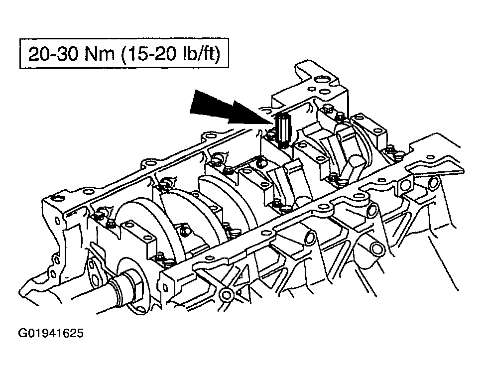
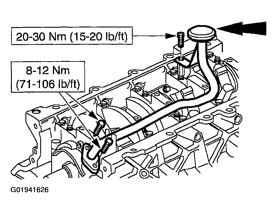
- Install the oil pump screen cover and tube spacer.
- Position the oil pump screen cover and tube, and install the bolts.
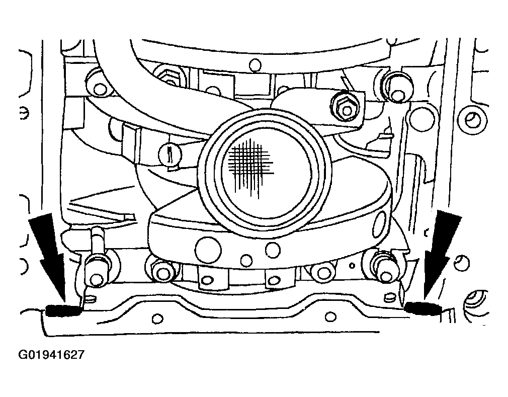
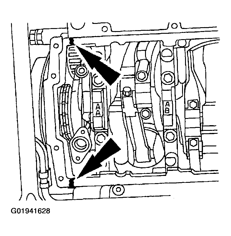
- Apply the sealant at the rear oil seal retainer to cylinder block sealing surface.
- Apply sealant at the front cover to cylinder block sealing surface.
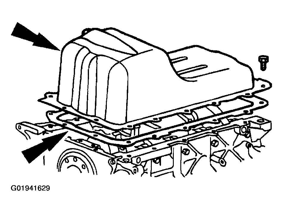
- Position the oil pan gasket, the oil pan and the bolts on the engine.
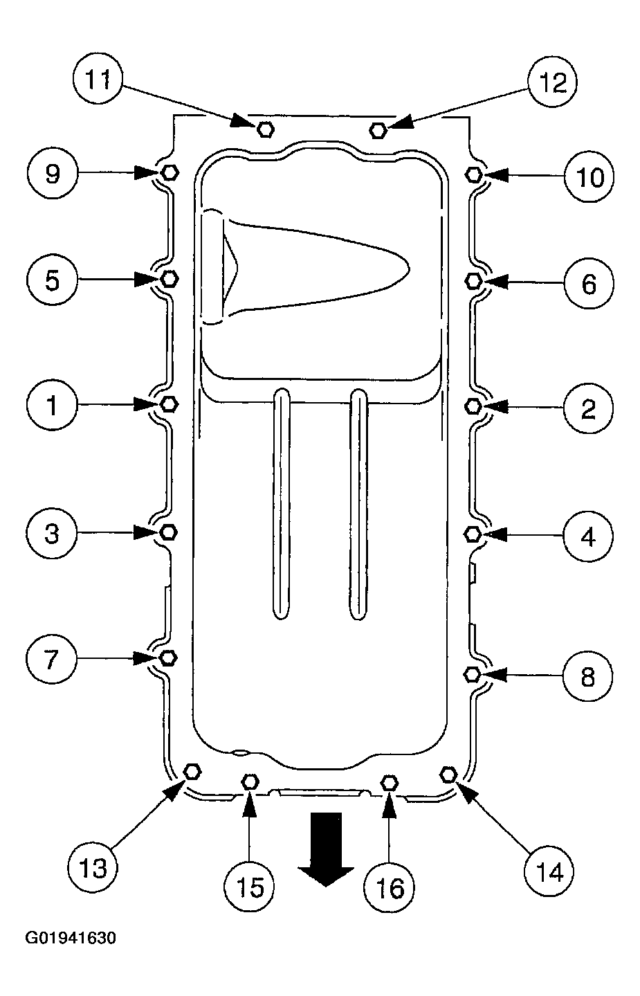
- Tighten the bolts in three stages, in the sequence shown.
- Stage 1: Tighten to 2 N.m (18 lb-in).
- Stage 2: Tighten to 20 N.m (15 lb-ft).
- Stage 3: Rotate an additional 60 degrees.
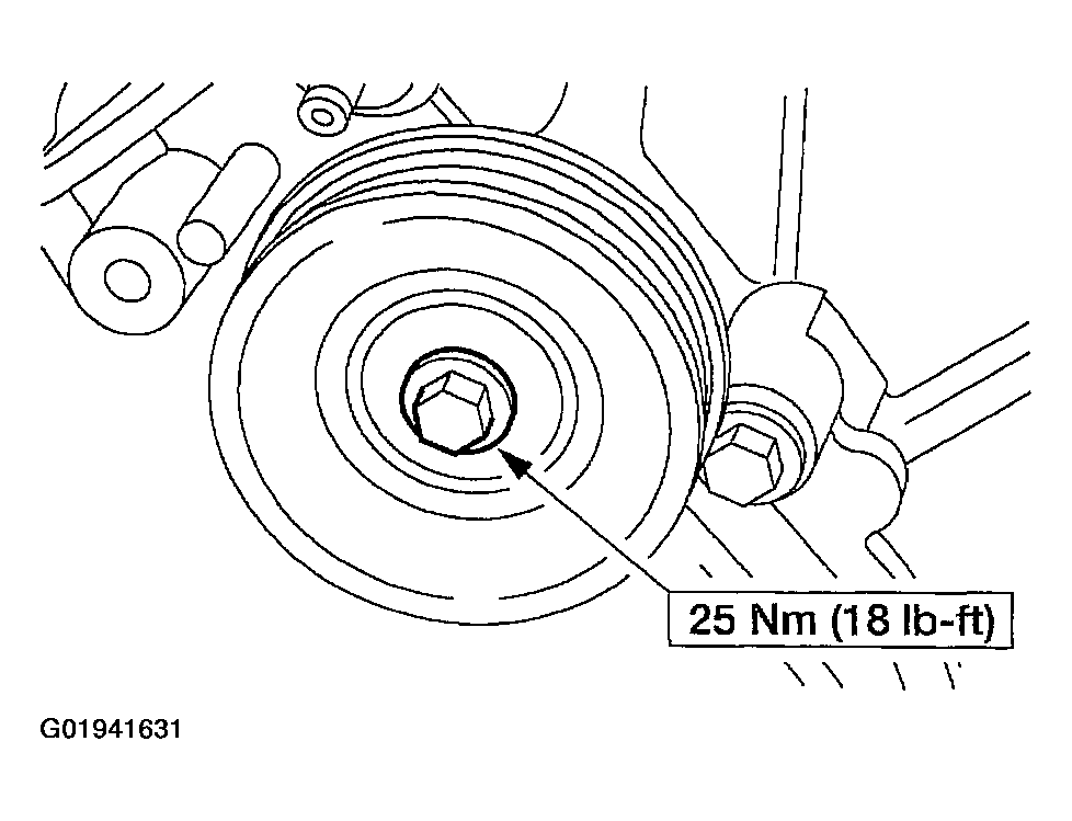
- Position the belt idler pulley and install the bolt.
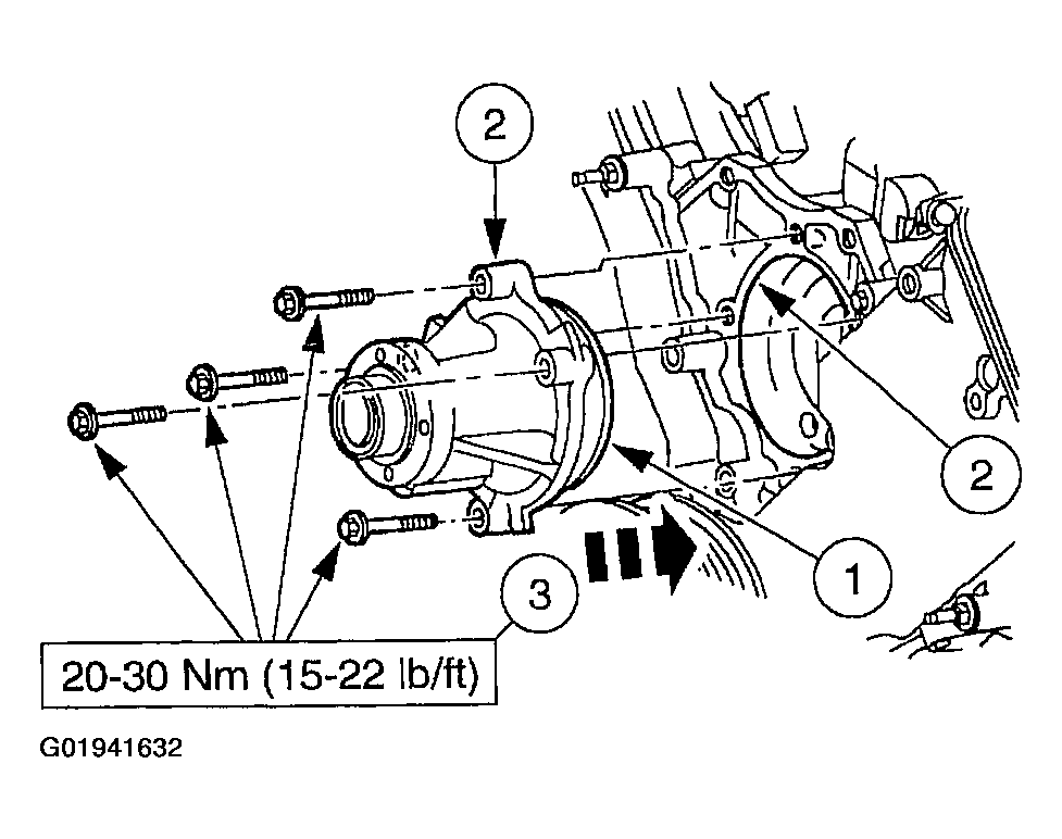
- Install the water pump. Refer to WATER PUMP under REMOVAL AND INSTALLATION.
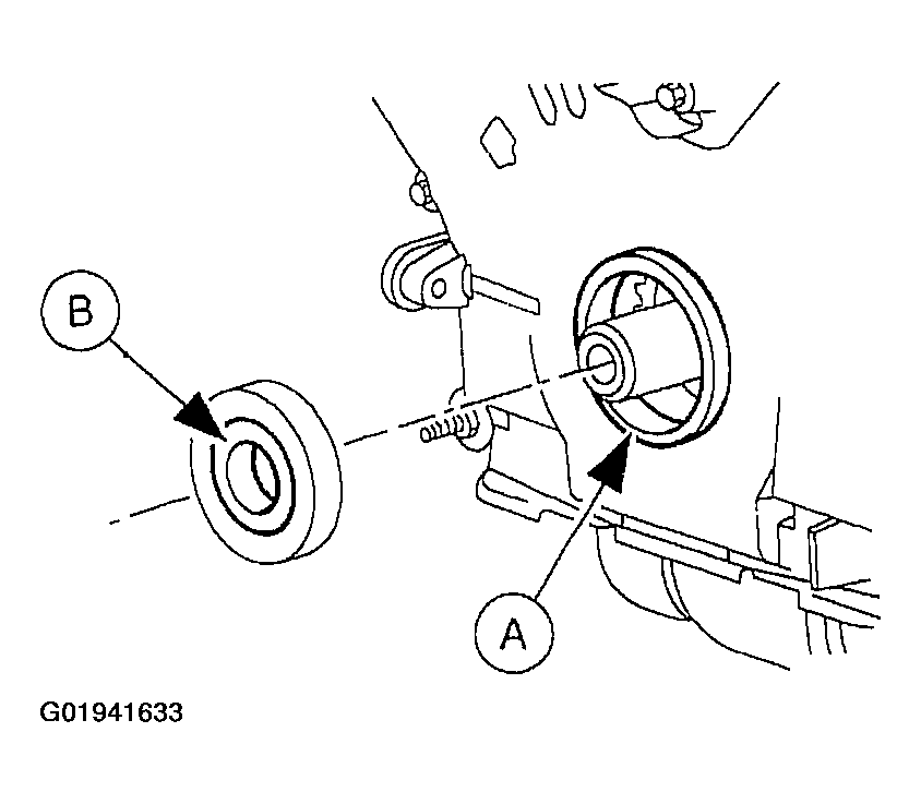
- Lubricate the (A) engine front cover and the (B) front oil seal inner lip with clean engine oil.
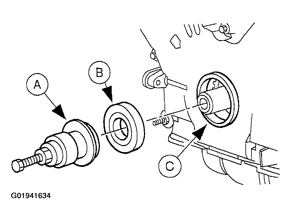
- Use the (A) Crankshaft Seal Installer/Aligner to install the (B) crankshaft front seal into the (C) engine front cover.
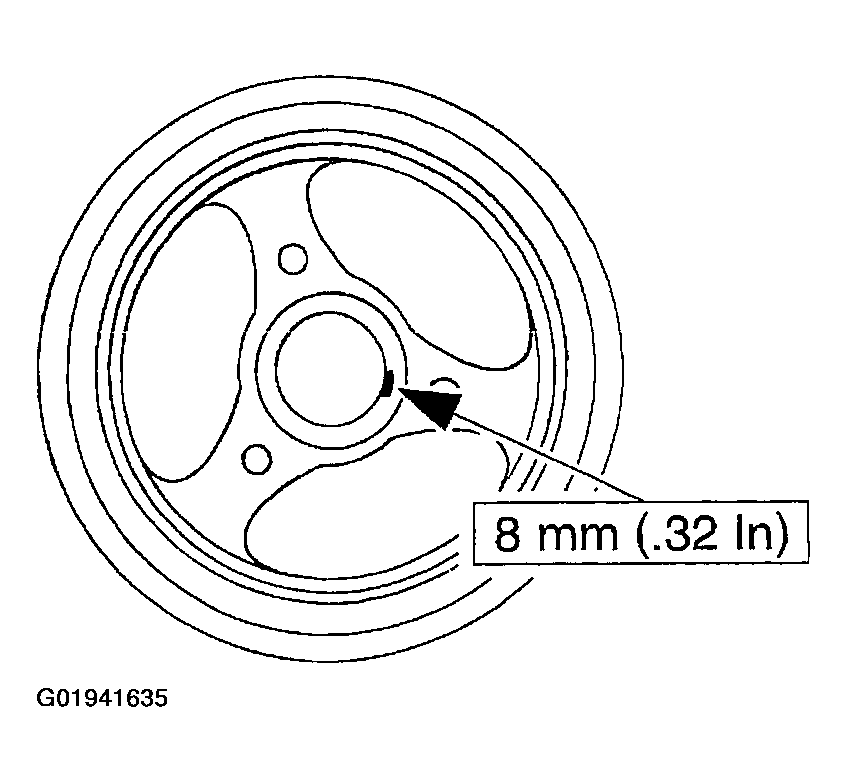
- Apply sealant to the Woodruff key slot on the crankshaft pulley.
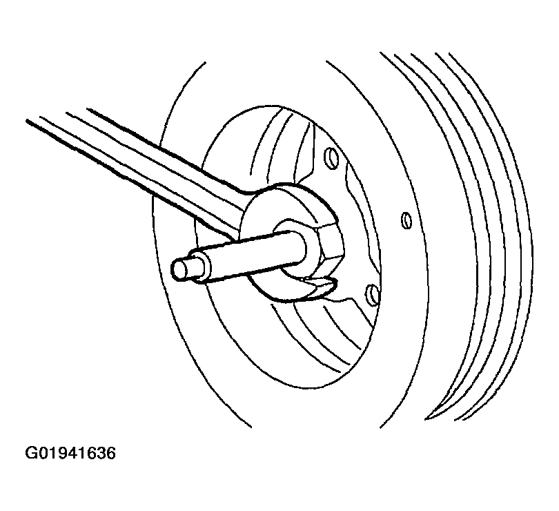
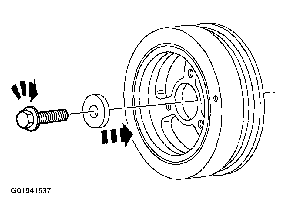
- Use the Crankshaft Damper Replacer to install the crankshaft pulley.
- Tighten the crankshaft pulley bolt in four stages.
- Stage 1: Tighten to 90 N.m (66 lb-ft).
- Stage 2: Loosen 360 degrees.
- Stage 3: Tighten to 47-53 Nm (35-39 lb-ft).
- Stage 4: Rotate an additional 85-90 degrees.
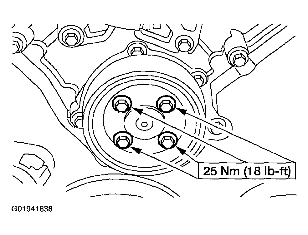
- Position the water pump pulley on the water pump and install the bolts. Refer to WATER PUMP under REMOVAL AND INSTALLATION.
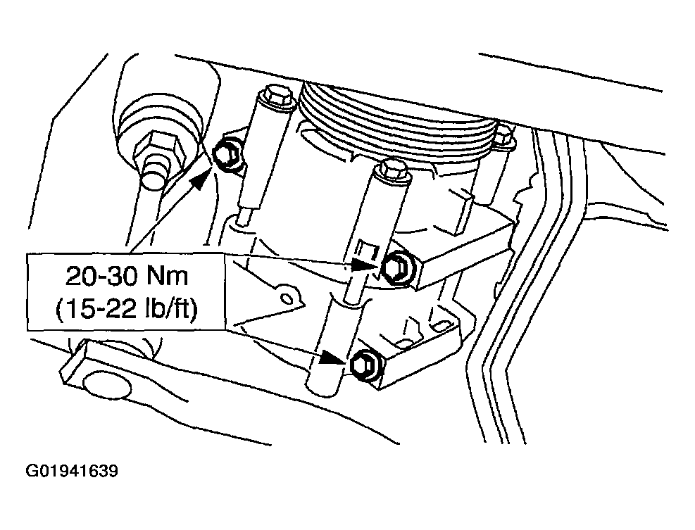
- Install the air conditioning compressor.
- Install the four bolts.
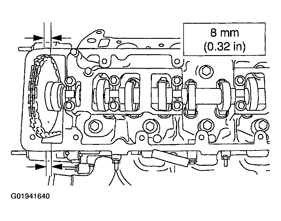
- Apply sealant in two places where the engine front cover meets the cylinder head.
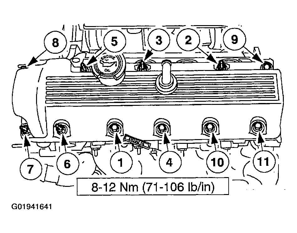
- Install the gasket into the valve cover and position the left valve cover on the cylinder head and tighten the bolts in the sequence shown.
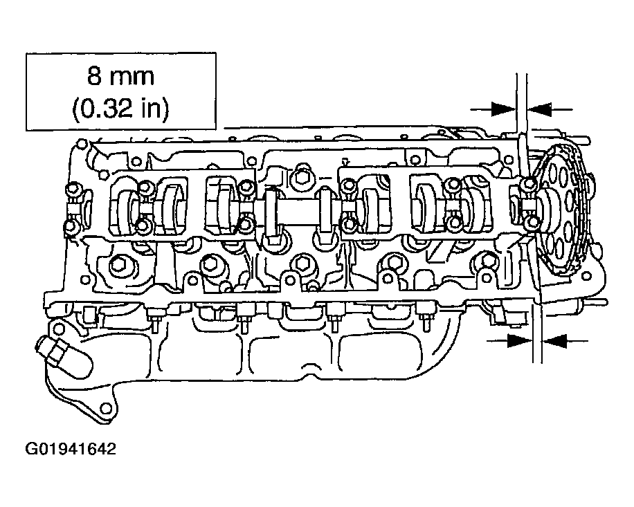
- Apply sealant in two places where the engine front cover meets the cylinder head.
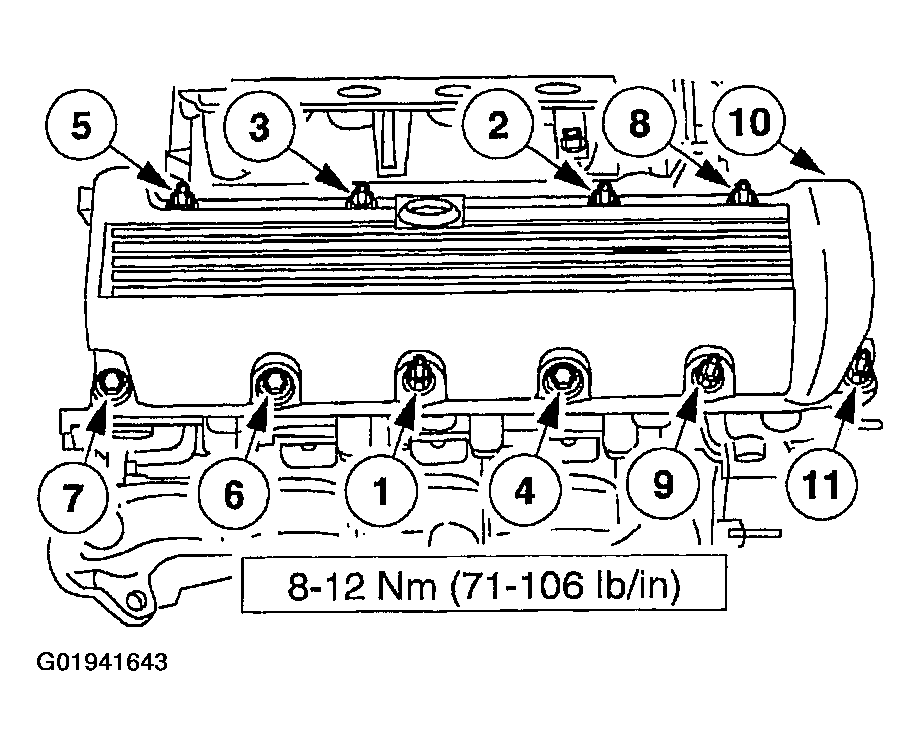
- Position the right valve cover and gasket and tighten the bolts in the sequence shown.
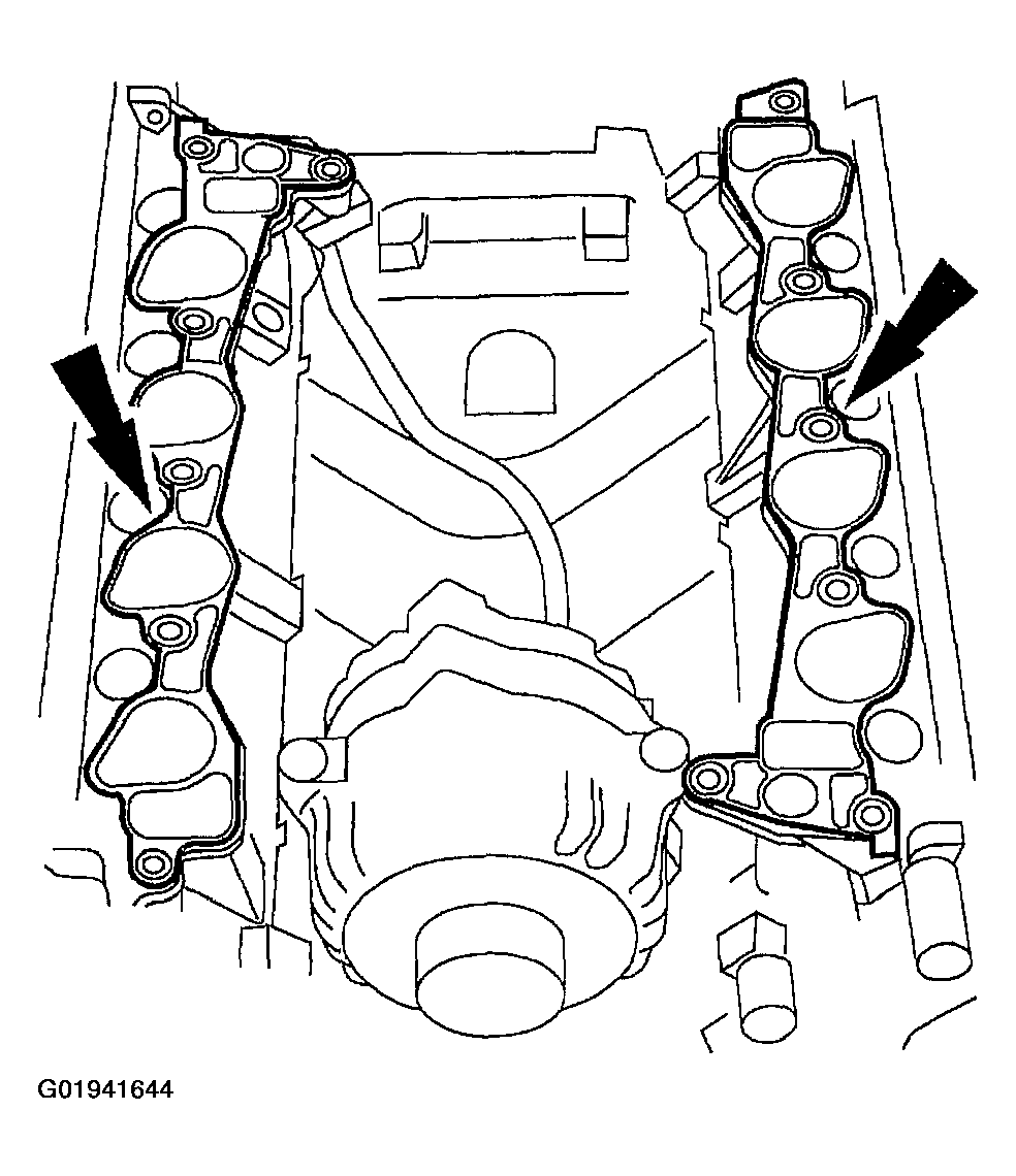
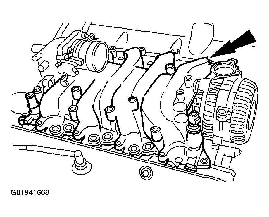
- Install new intake manifold gaskets.
Gasoline Engines
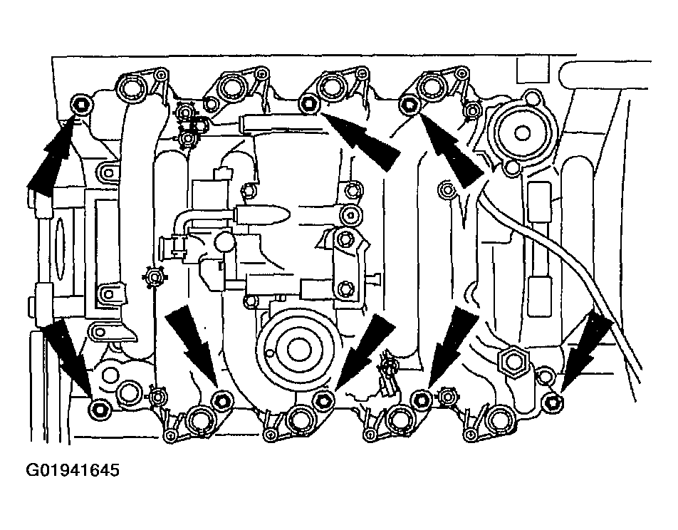
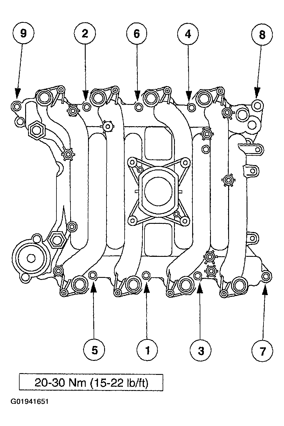
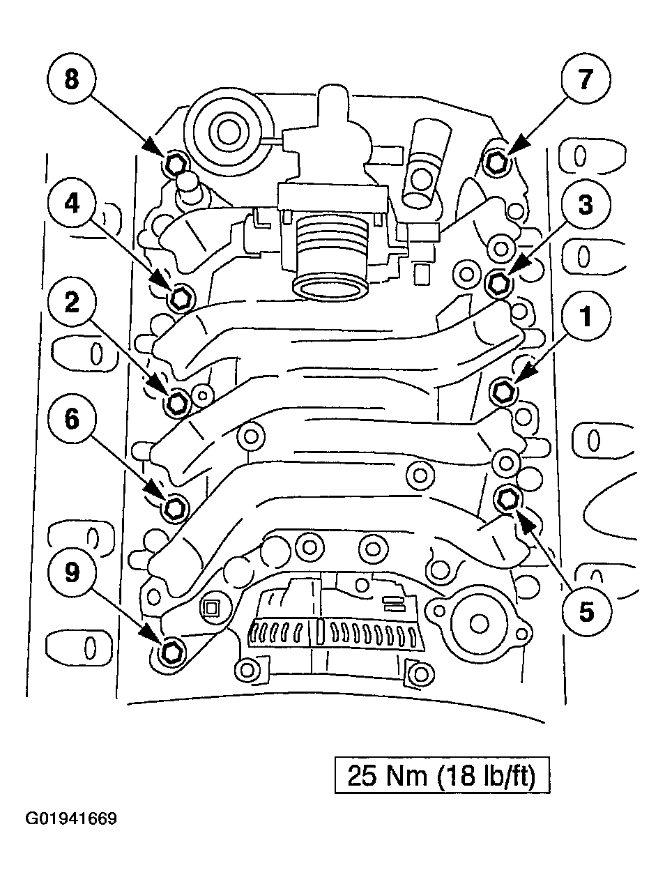
- Install the intake manifold and hand-tighten the bolts at the locations shown.
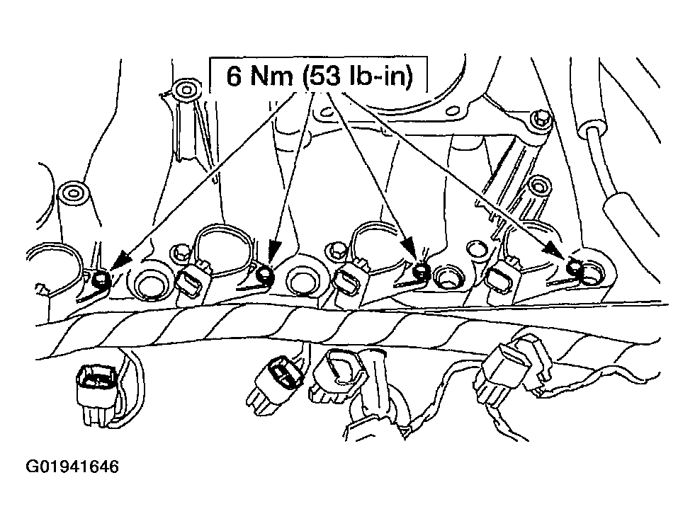
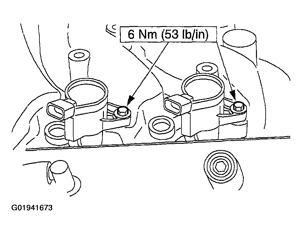
- Install the eight ignition coils and tighten the eight bolts.
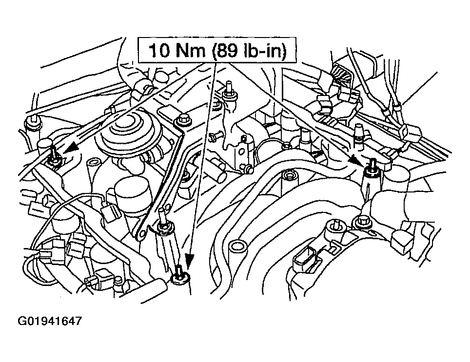
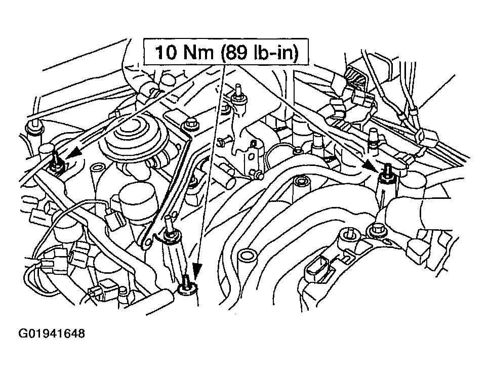
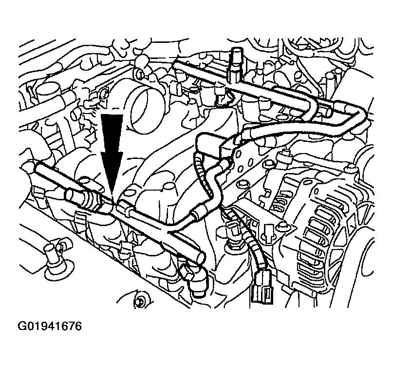
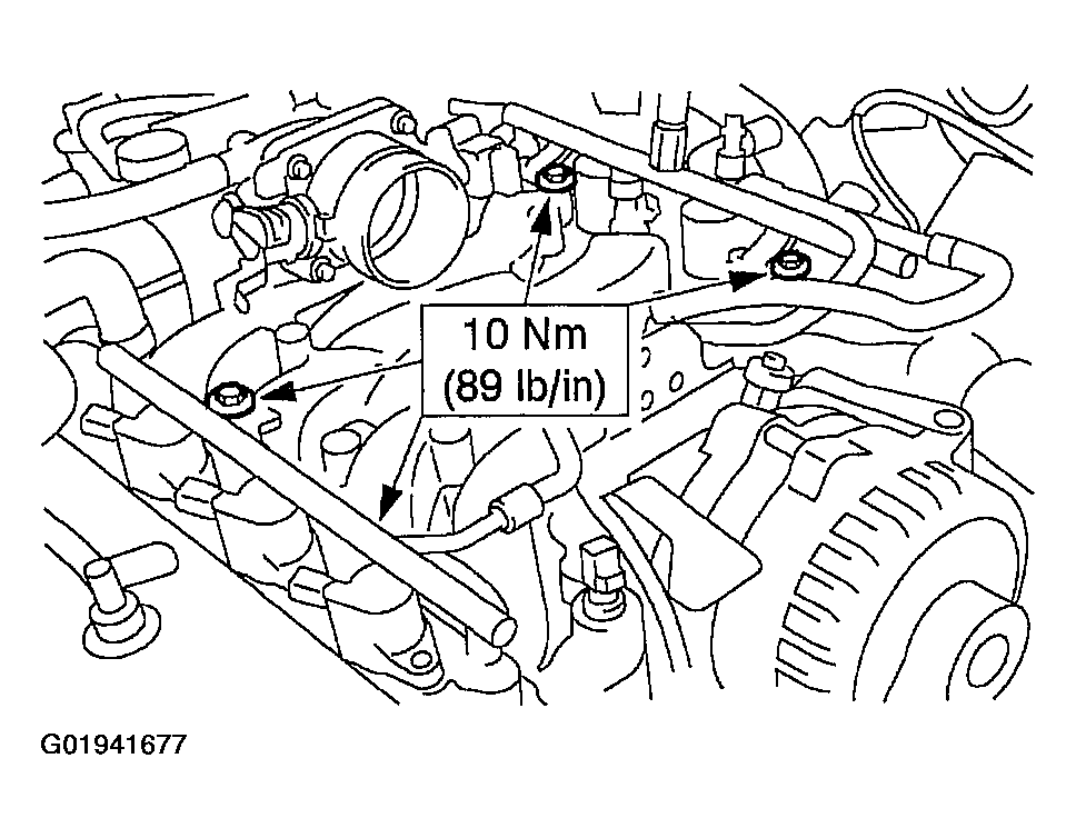
- Install the fuel injectors and the fuel injection supply manifold as an assembly and tighten the four studs.
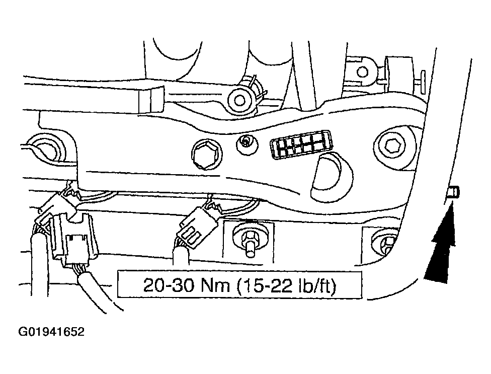
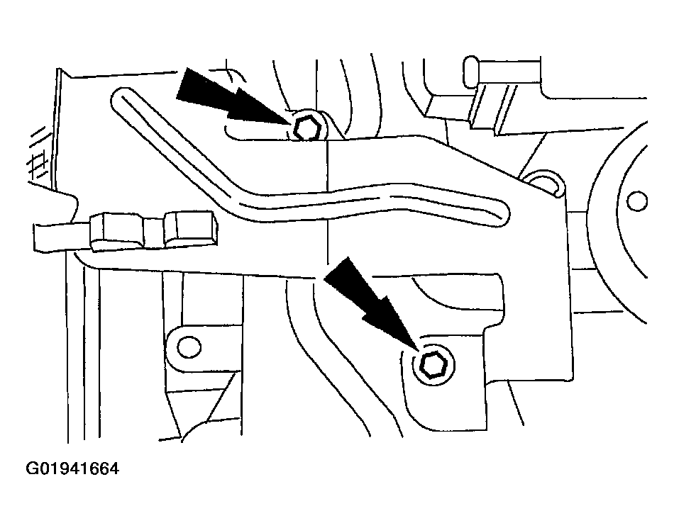
- Install the crash bracket and loosely install the bolt and the stud.
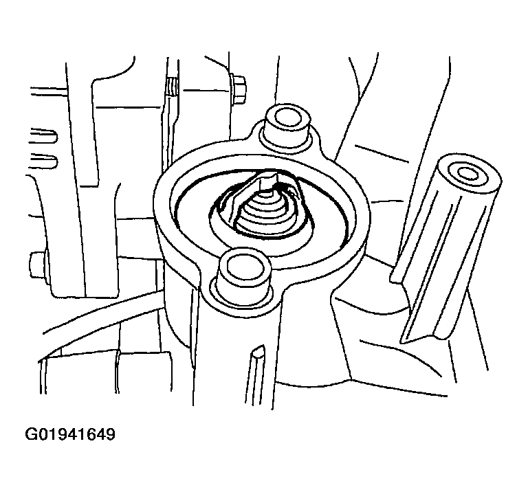
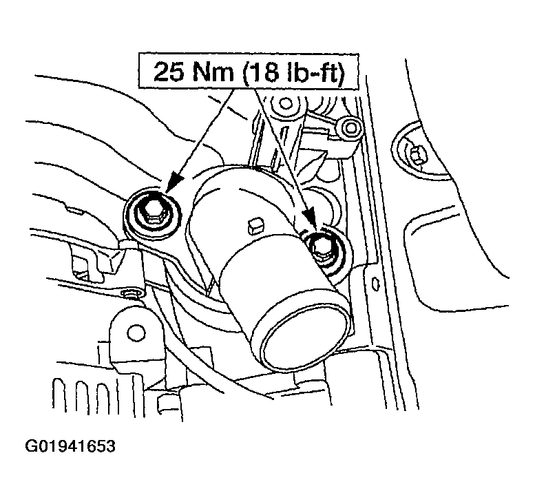
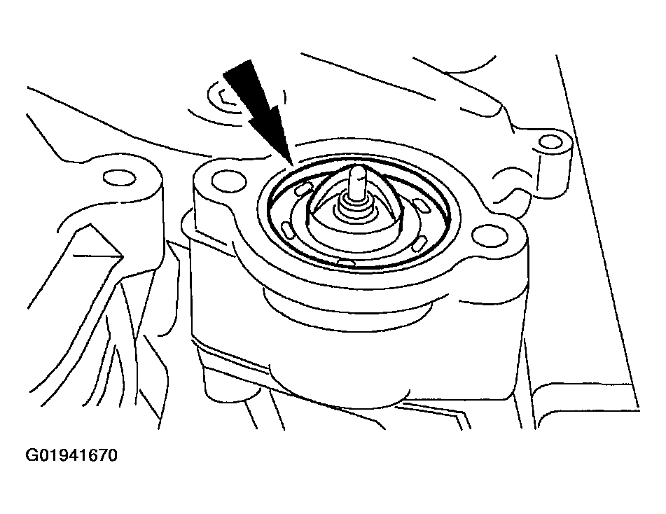
- Install the water thermostat.
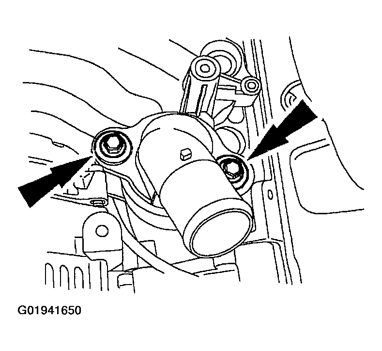
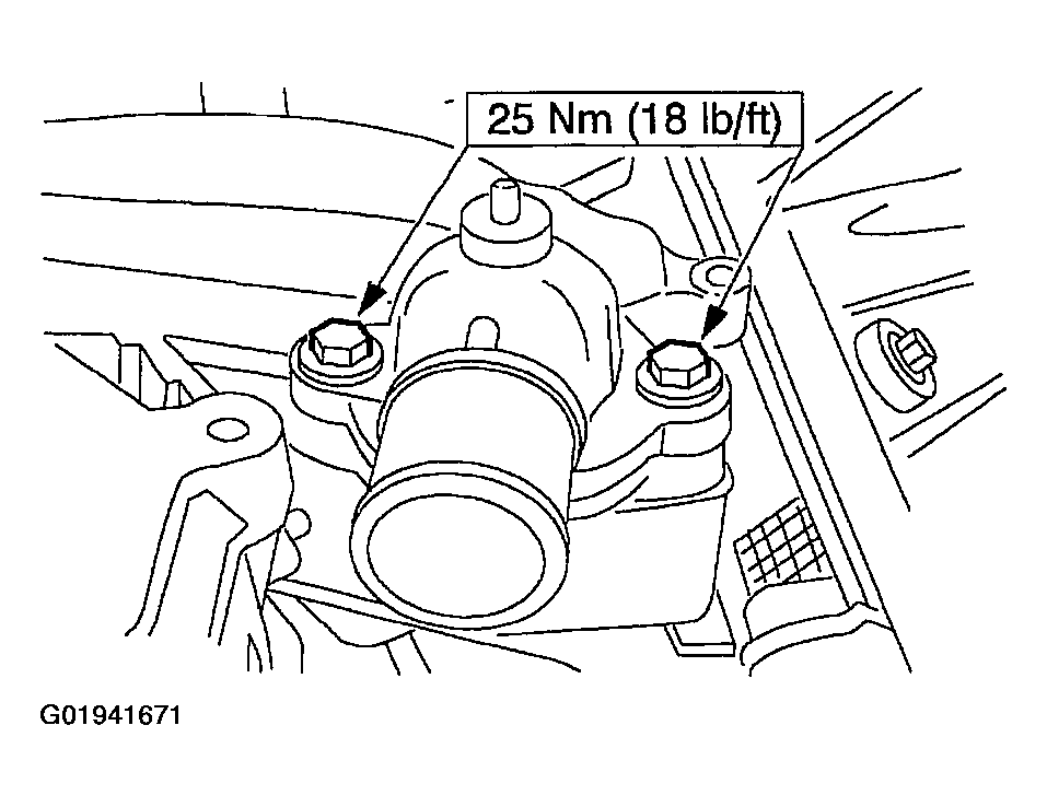
- Install the water outlet adapter and loosely install the bolts.
- Tighten the bolts in the sequence shown.
- Tighten the stud.
- Tighten the bolts.
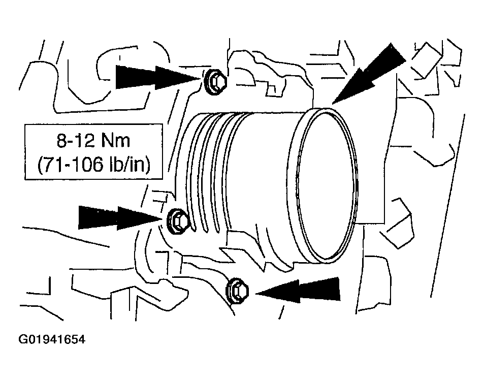
- Install the throttle body and tighten the bolts.
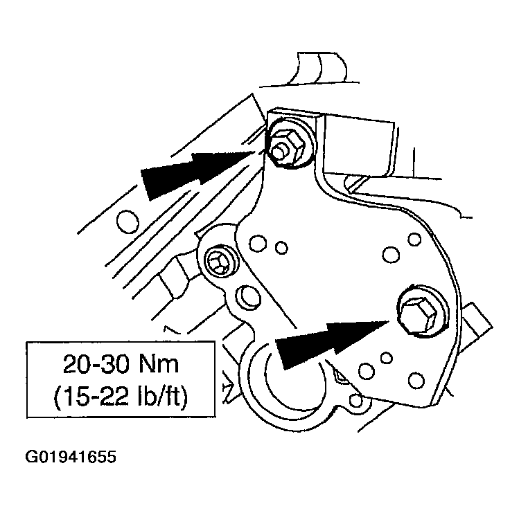
- Install the transmission harness support bracket.
- Position the bracket.
- Install the nut and the bolt.
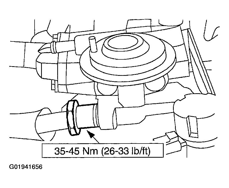
- Connect the exhaust gas recirculation (EGR) tube to the EGR valve.
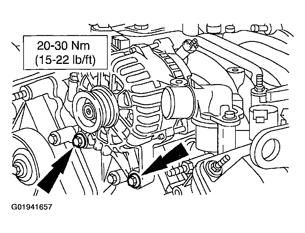
- Install the generator.
- Install the two bolts.
- Position the fuel charging wiring at two locations at the back of the intake manifold.
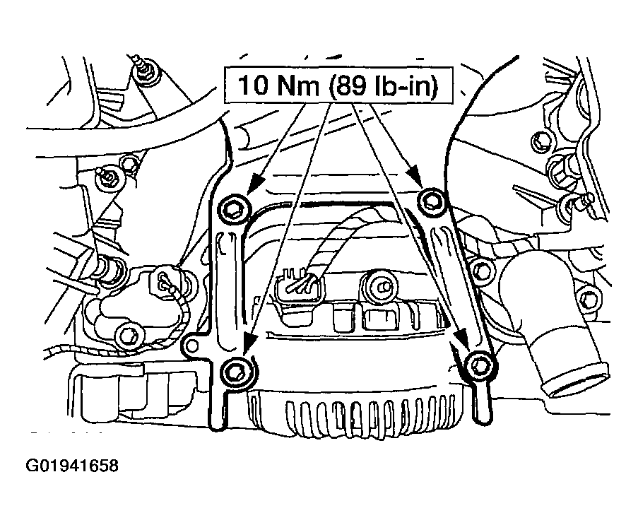
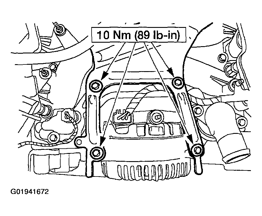
- Position the generator mounting bracket and install the bolts.
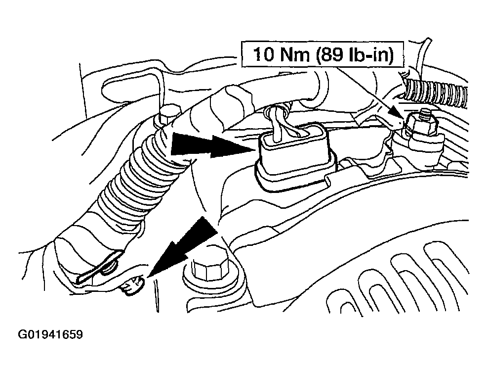
- Connect the electrical connector, the generator cable and the harness pin-type retainer.
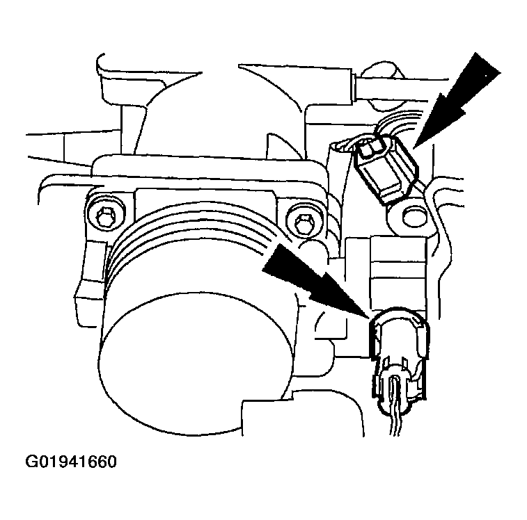
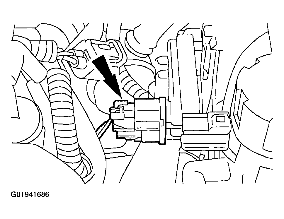
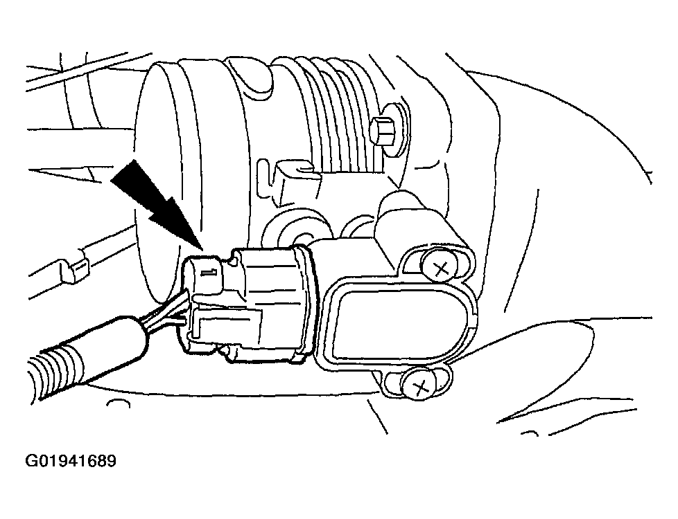
- Connect the electrical connector to the idle air control (IAC) valve and the throttle position (TP) sensor.
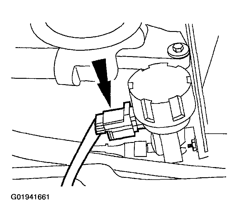
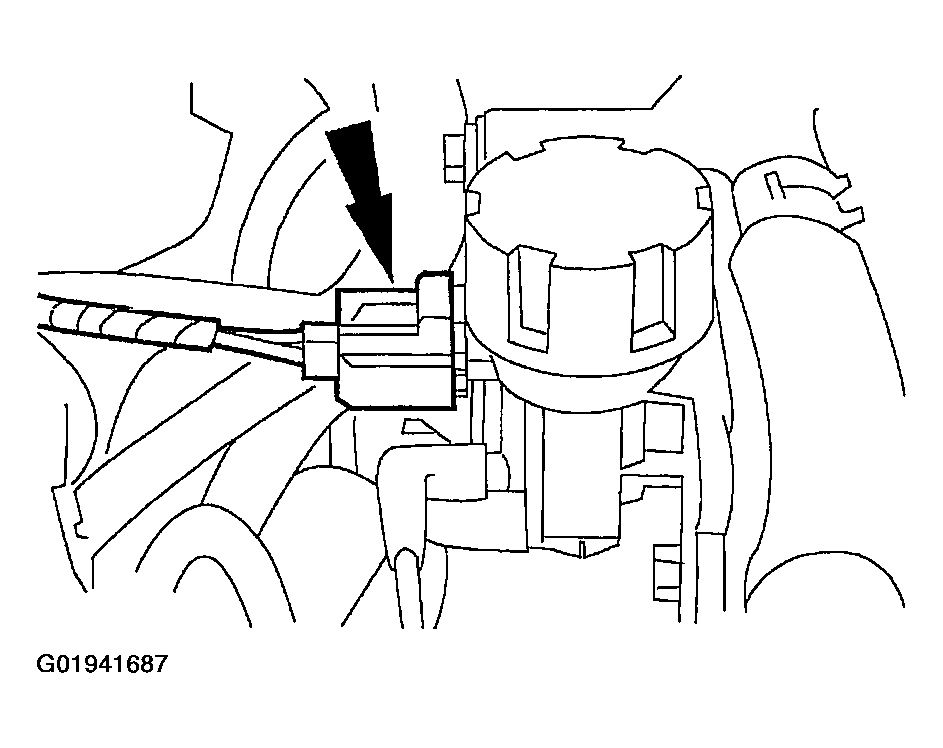
- Connect the electrical connector to the EGR vacuum regulator solenoid.
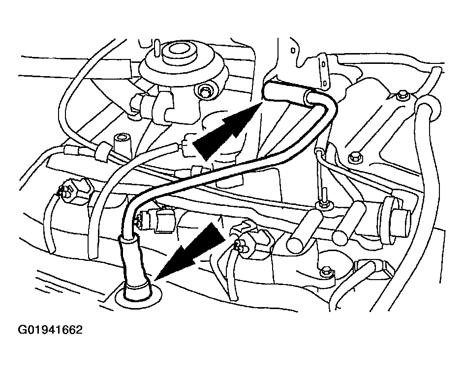
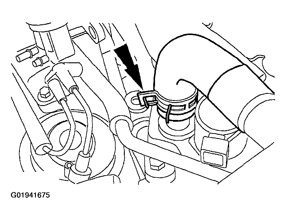
- Connect the crankcase ventilation tube.
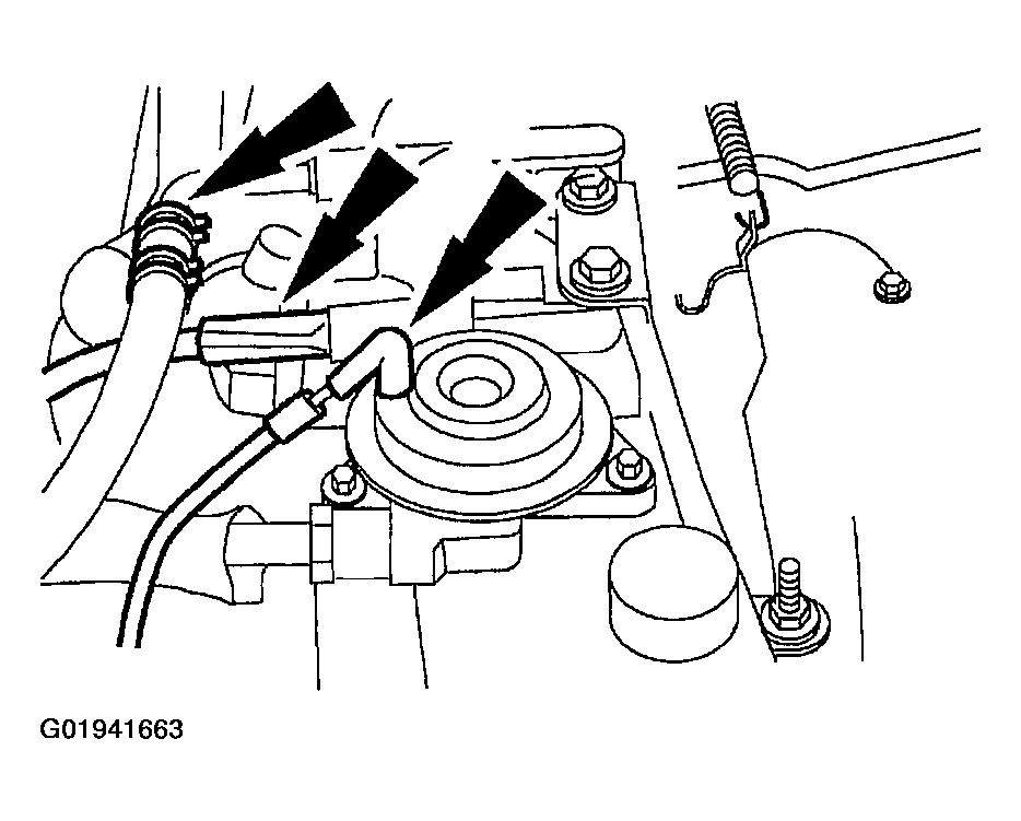
- Position the vacuum harness and connect the vacuum lines for the evaporative emission (EVAP) canister purge valve, the main chassis line and the EGR valve.
- Position the EGR tube heat shield and install the bolts.
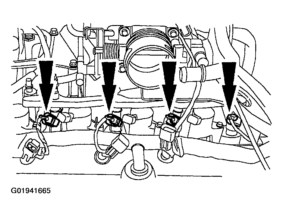
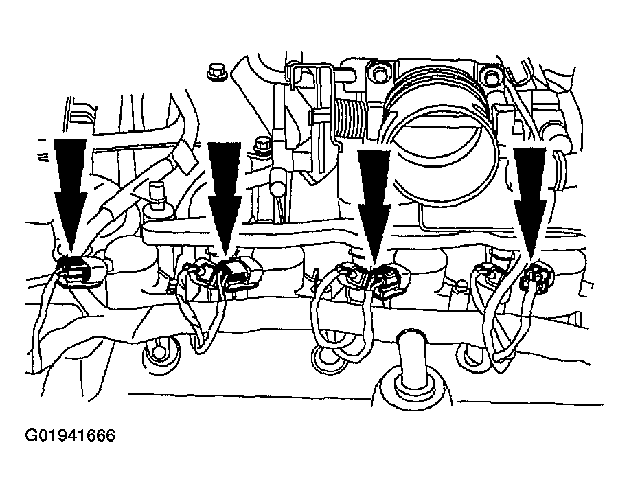
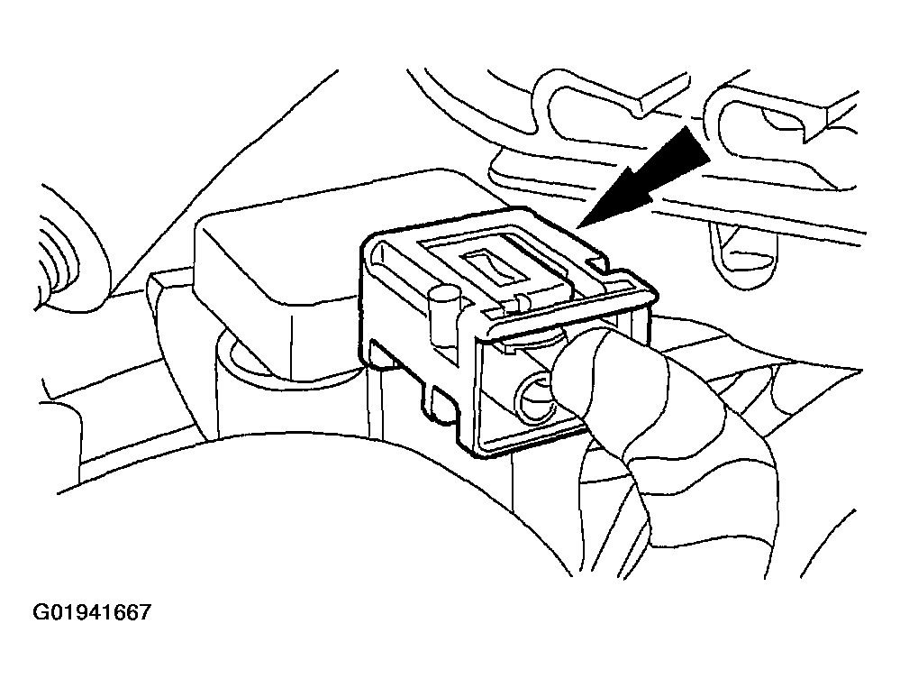
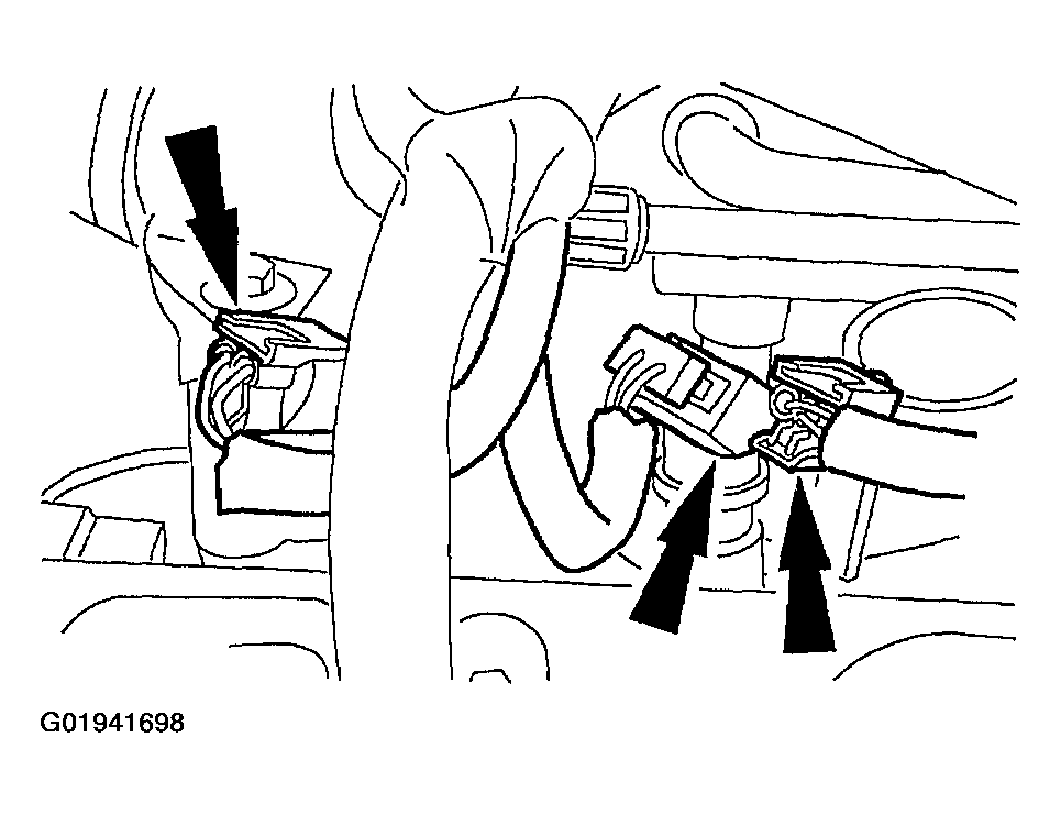
- Connect the fuel charging wiring electrical connectors to the eight fuel injectors.
- Connect the fuel charging wiring electrical connectors to the eight ignition coils.
- Connect the two differential pressure feedback EGR connectors.
Natural Gas Engines
- Install the intake manifold.
- Install the bolts and tighten in the sequence shown.
- Install the water thermostat and a new O-ring seal.
- Install the water outlet adapter and tighten the bolts.
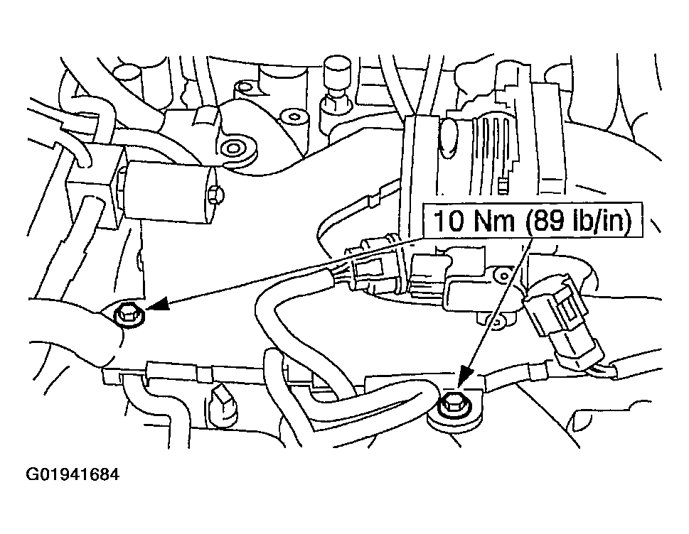
- Install the generator support bracket and tighten the bolts.
- Install the eight ignition coils and tighten the bolts.
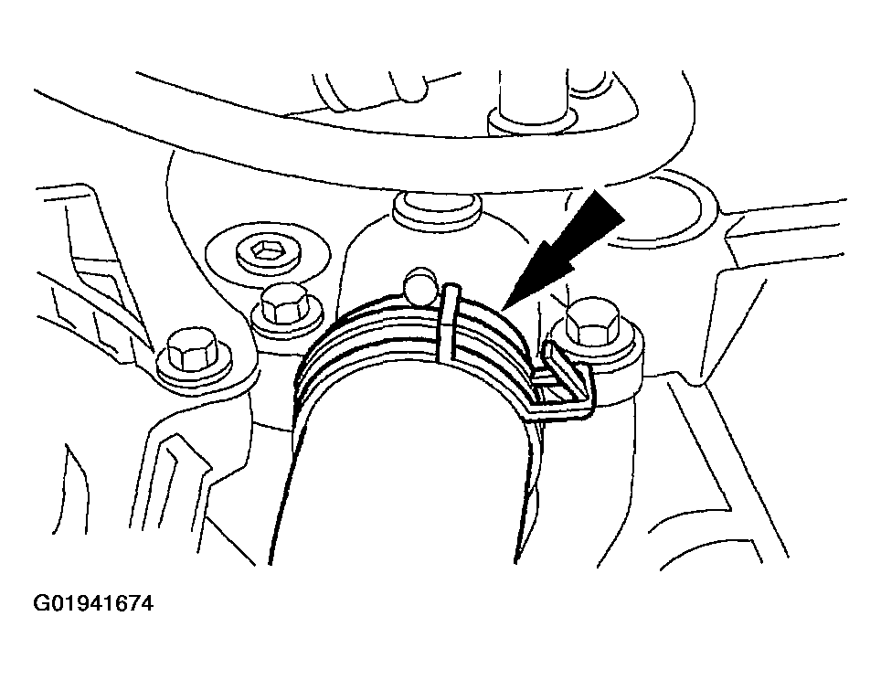
- Connect the upper radiator hose to the water outlet adapter.
- Connect the heater water hose to the intake manifold.
- Install the fuel injectors and the fuel injection supply manifold as an assembly.
- Install the four bolts.
- Install the bolts in the isolation valve and tighten.
- Connect the EGR tube to the EGR valve.
- Connect the vacuum lines to the EGR vacuum regulator solenoid.
- Connect the vacuum hoses to the throttle body adapter.
- Install the crankcase ventilation tube and connect at two locations.
- Connect the vacuum hose to the EGR valve.
- Reposition the fuel charging wiring and install the bolts.
- Connect the fuel charging wiring to the idle air control valve.
- Connect the fuel charging wiring to the differential pressure feedback EGR system electrical connector.
- Connect the fuel charging wiring to the EGR vacuum regulator solenoid.
- Connect the fuel charging wiring to the radio ignition interference capacitor.
- Connect the fuel charging wiring electrical connector to the TP sensor.
- Connect the fuel charging wiring electrical connector to the generator.
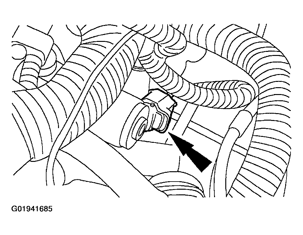
- Connect the fuel charging wiring electrical connector to the camshaft position (CMP) sensor.
- Connect the fuel charging wiring electrical connector to the cylinder head temperature sensor jumper.
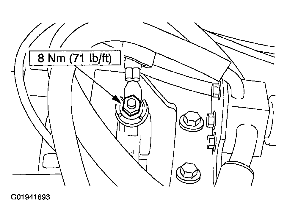
- Connect the generator battery cable and tighten the nut.
- Connect the isolation valve jumper to the fuel charging wiring electrical connector and reposition on the upper generator support bracket.
- Connect the fuel charging wiring electrical connector to the engine coolant temperature sensor.
- Connect the fuel charging wiring electrical connector to the fuel temperature sensor.
- Connect the fuel charging wiring electrical connector to the fuel pressure sensor.
- Connect the fuel charging wiring electrical connectors to the eight ignition coils and the eight fuel injectors.
All Engines
- Connect the EGR tube to the exhaust manifold connector.
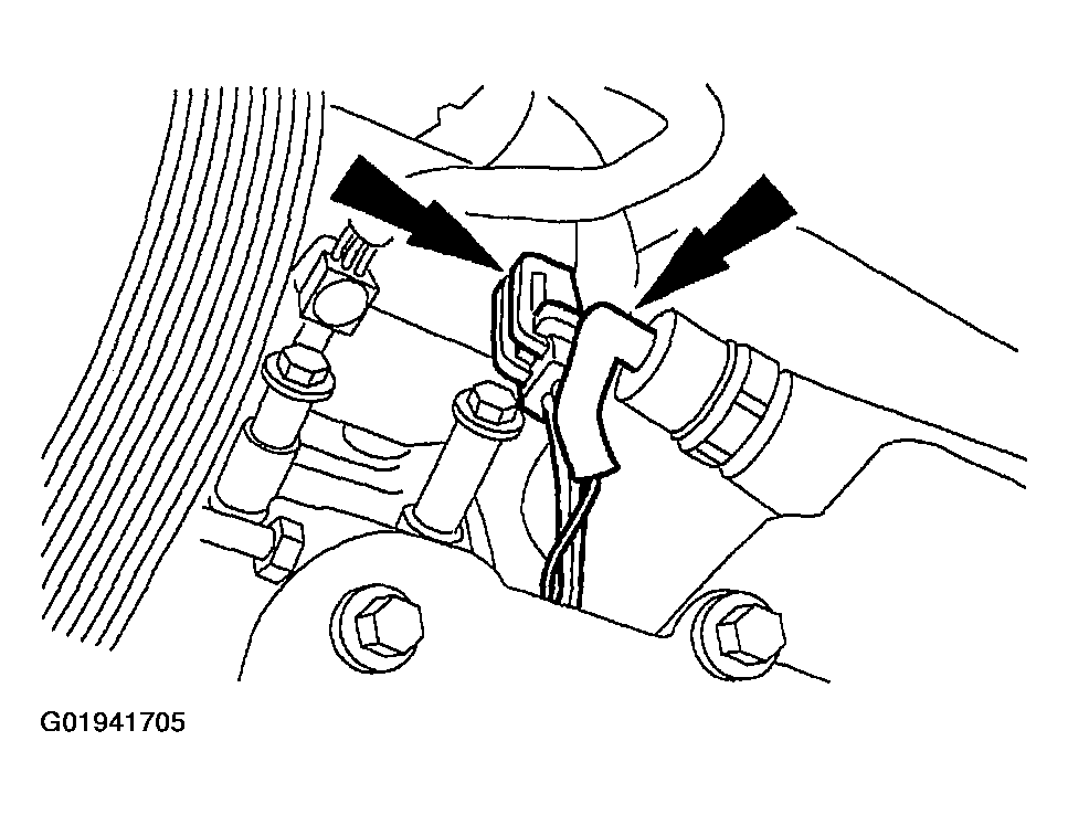
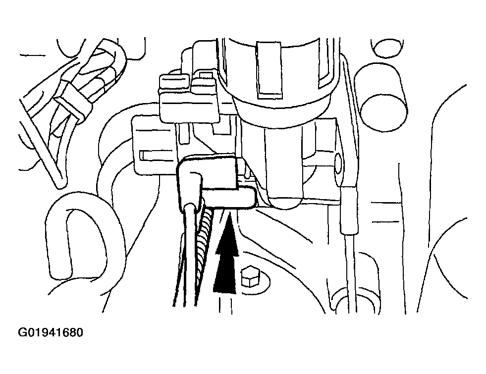
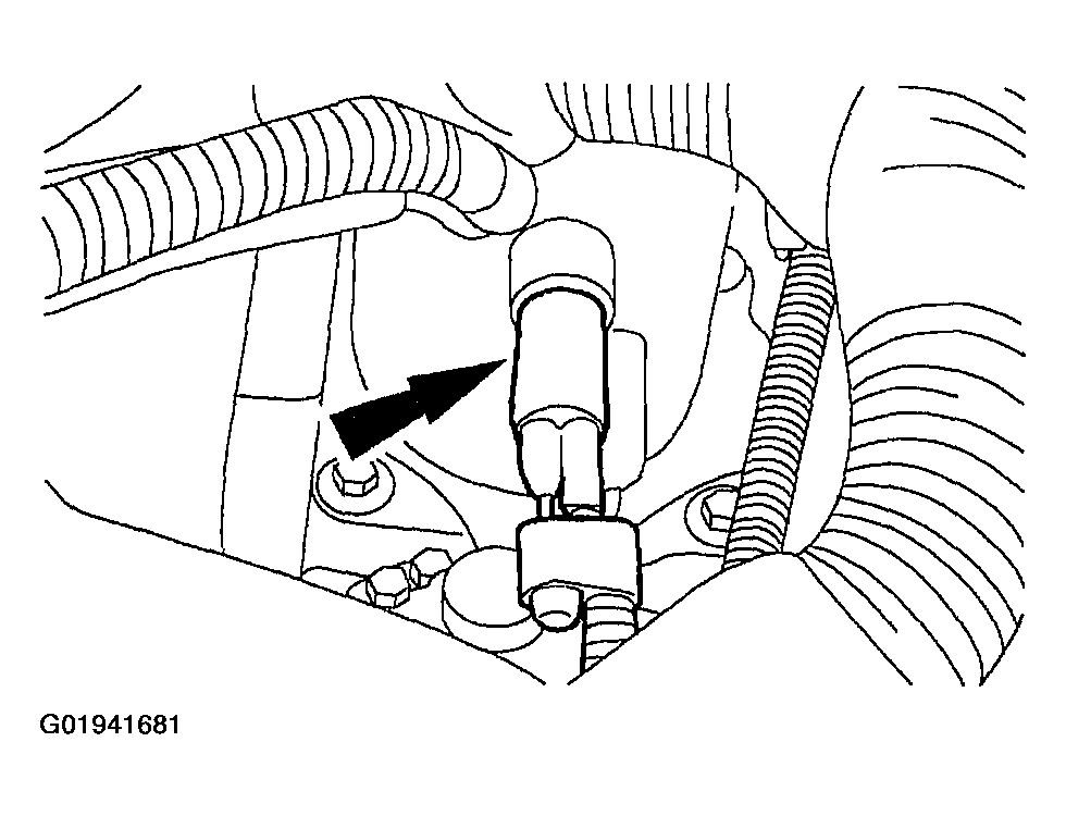
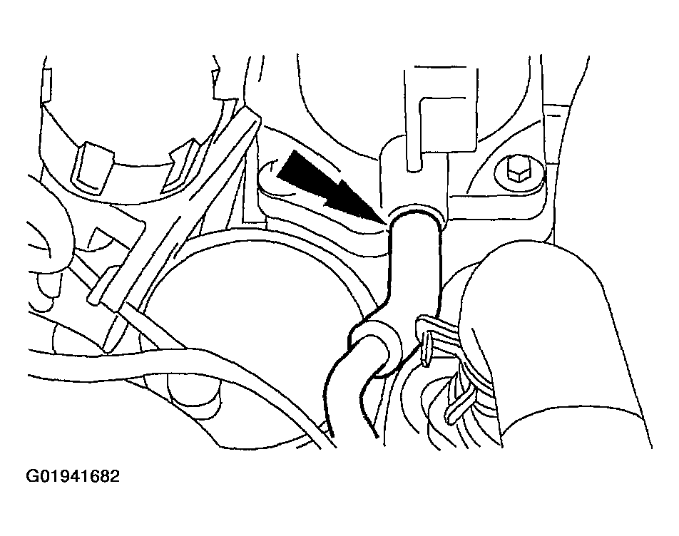
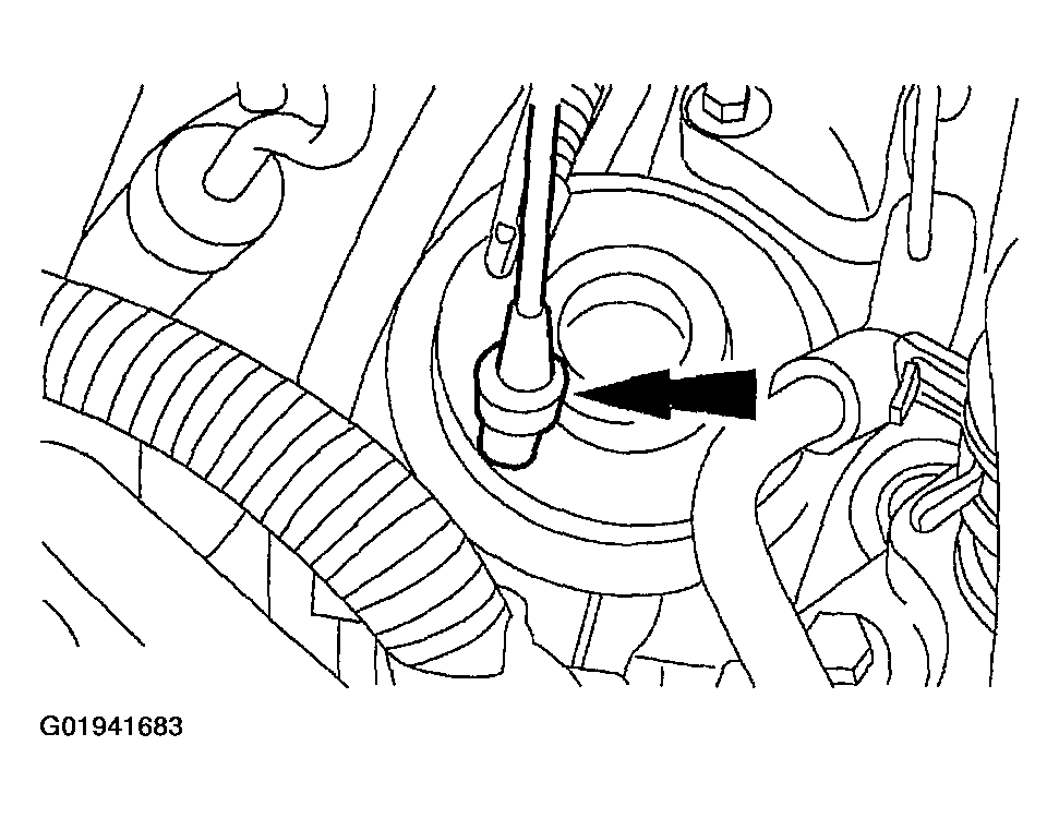
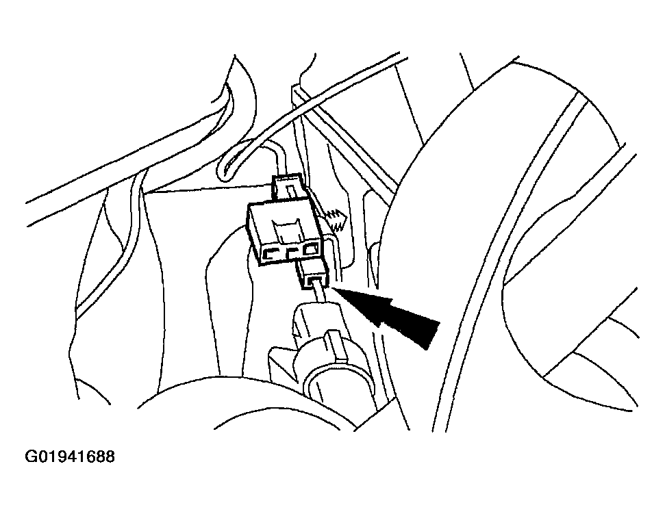
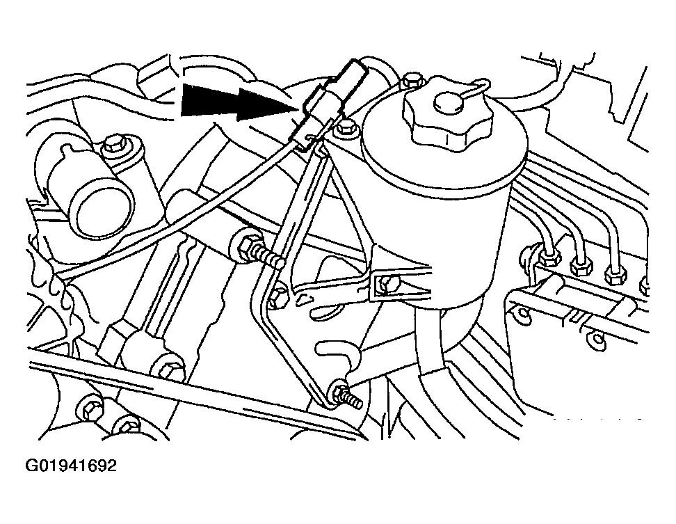
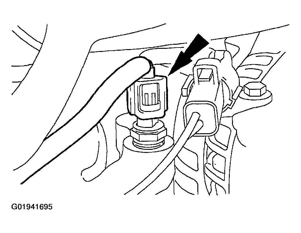
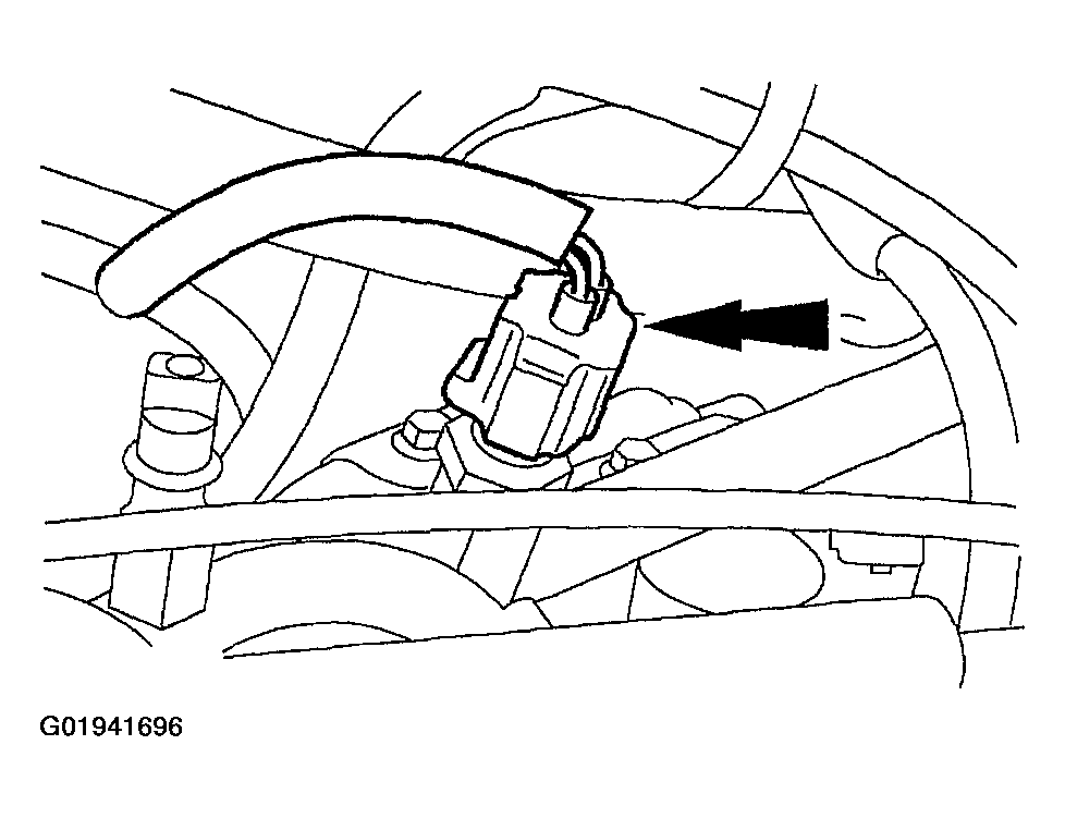
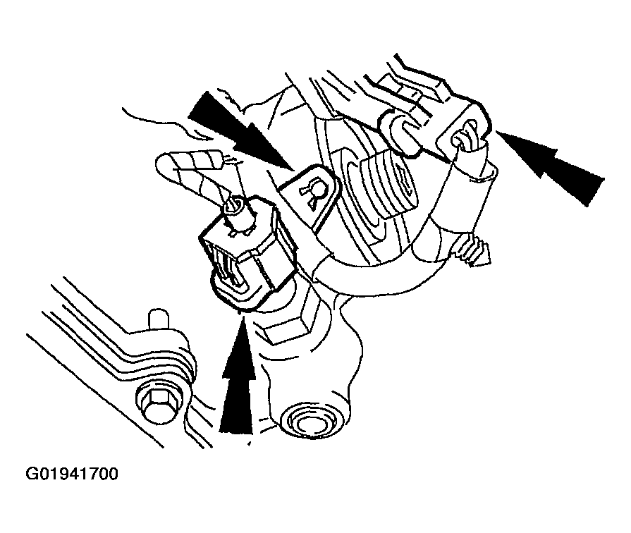
- Connect the electrical connector to the engine oil pressure (EOP) sensor, the power steering (PSP) switch and the harness pin-type retainer.
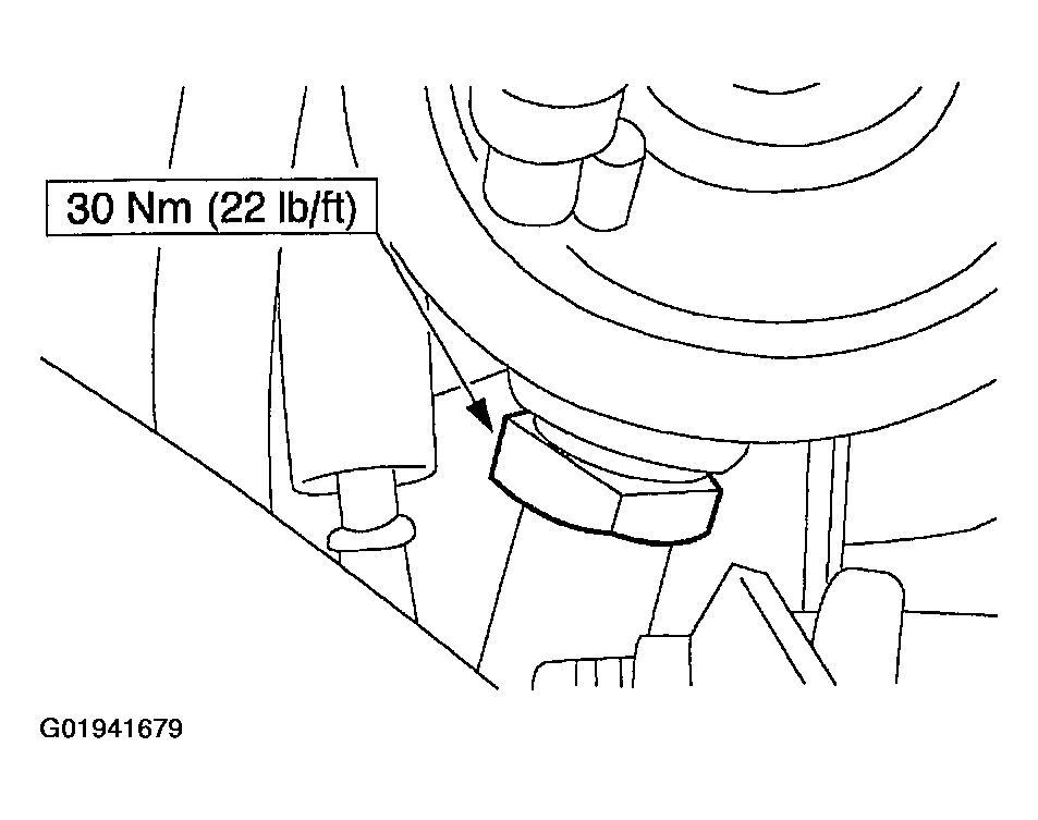
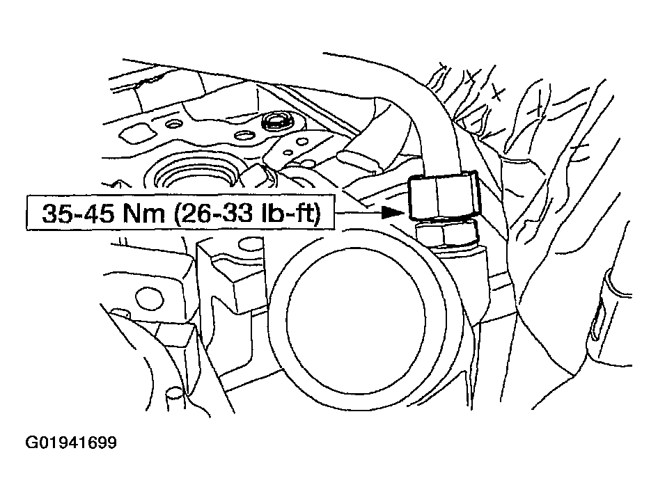
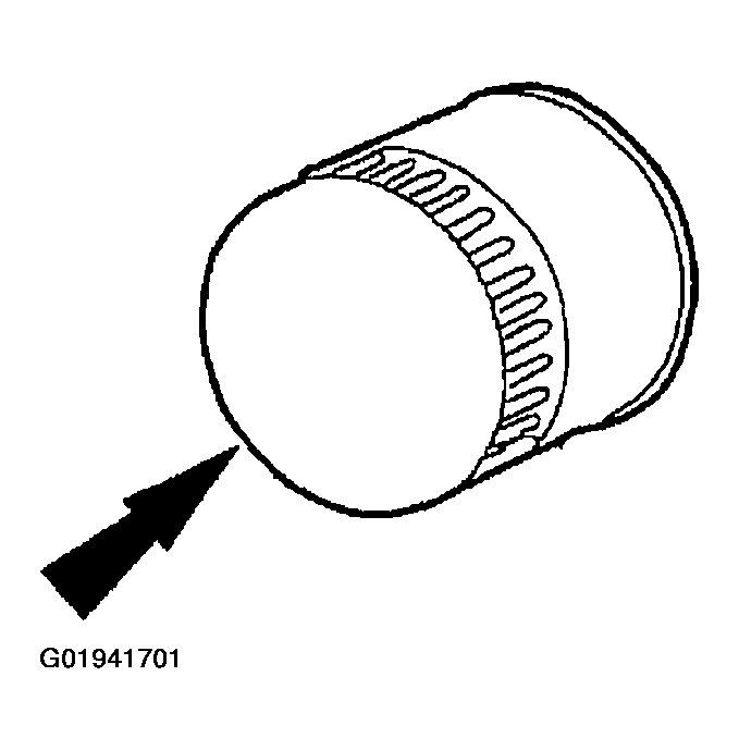
- Install the oil bypass filter.
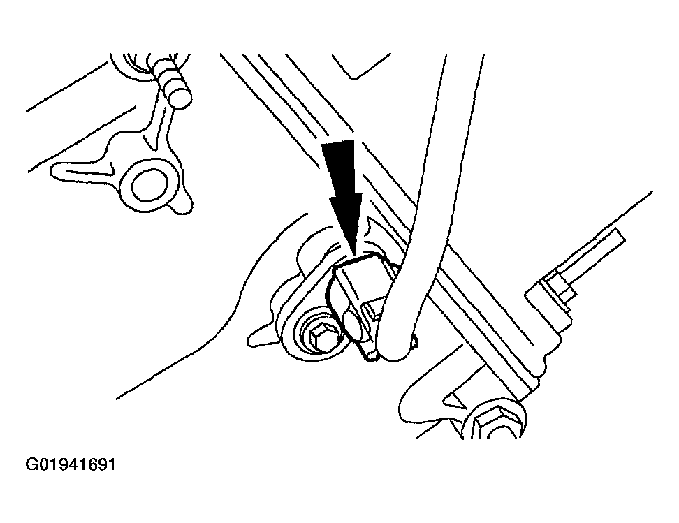
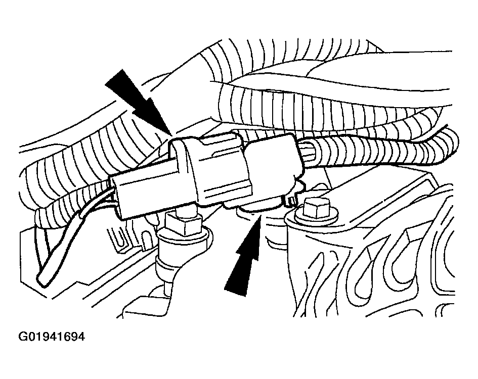
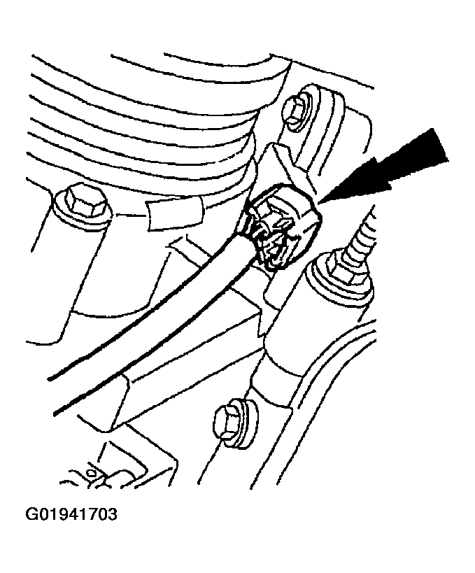
- Connect the fuel charging wiring electrical connector to the A/C compressor.
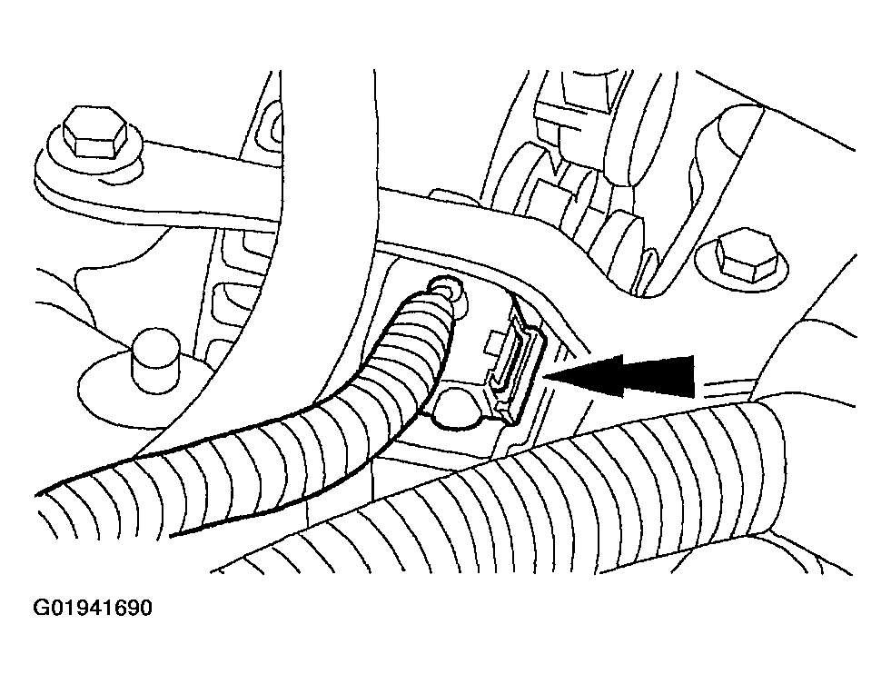
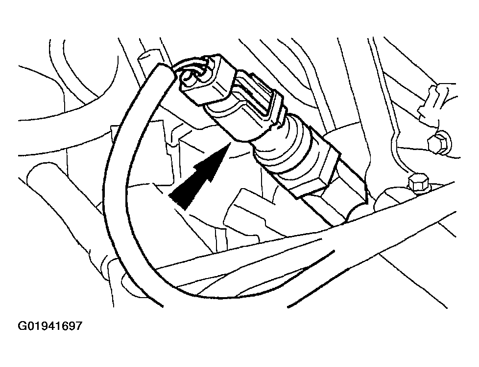
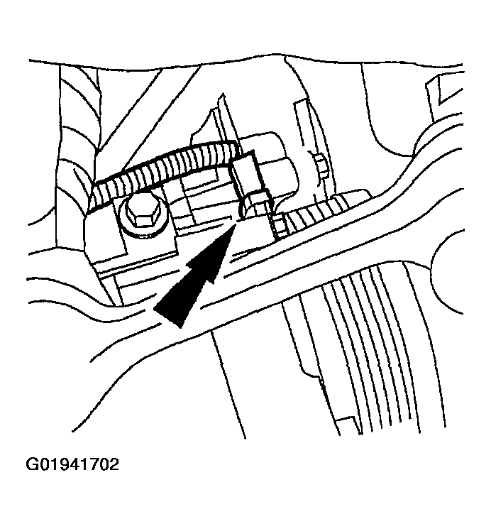
- Connect the fuel charging wiring electrical connector to the crankshaft position (CKP) sensor.
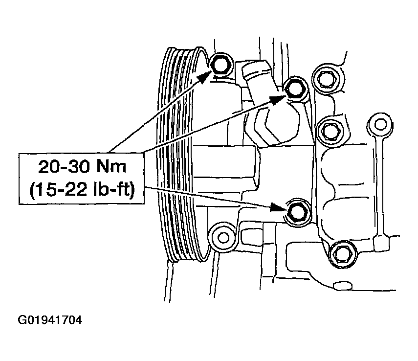
- Install the power steering pump.
- Position the power steering pump.
- Install the bolts.
- Connect the electrical connector to the engine oil pressure (EOP) sensor and the power steering pressure (PSP) switch.
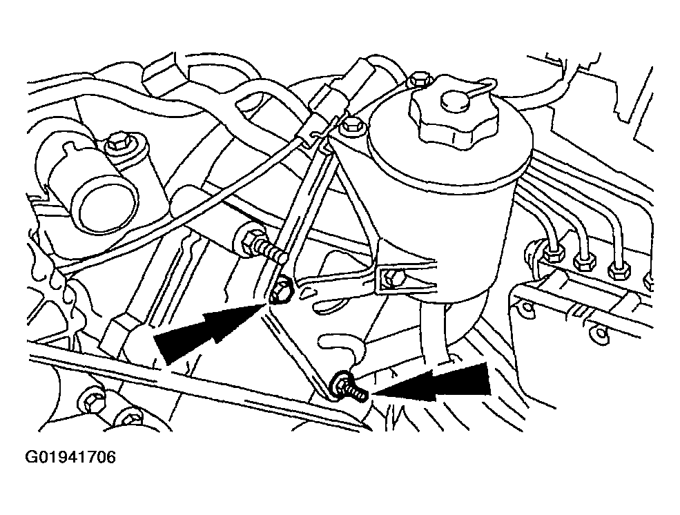
- Position the power steering reservoir and install the two studs and one bolt.
- Install the drive belt.
- Install the battery cables and the bolt.
CAUTION:
Before assembling the cylinder block, all sealing surfaces must be free of chips, dirt, paint and foreign material. Also, make sure the coolant and oil passages are clear.
NOTE:
To aid in assembly, apply petroleum jelly to the back of the crankshaft thrust washer.
NOTE:
The oil groove on the thrust washer must face toward the rear of the engine (crankshaft surface).
NOTE:
The jack screws are a part of the main bearing cap assembly, and are screwed into the main caps, not the cylinder block.
CAUTION:
Do not scratch the cylinder walls or crankshaft journals with the connecting rod.
NOTE:
Stages 8, 9 and 10 are for all eight connecting rods, rod caps and pistons. Only one connecting rod, rod cap and piston is shown.
CAUTION:
Do not scratch the cylinder walls or crankshaft journals with the connecting rod.
CAUTION:
The rod cap installation must keep the same orientation as marked during disassembly.
NOTE:
The connecting rod caps are of the cracked design and must mate with the connecting rod ends. Excessive bearing clearance can result if not mated correctly.
NOTE:
Main caps are not shown for clarity.
CAUTION:
Make sure all coolant residue and foreign material is cleaned from the block surface and cylinder bore.
NOTE:
RH is shown; LH is similar.
NOTE:
Do not turn the crankshaft until instructed to do so.
NOTE:
LH is shown; RH is similar.
NOTE:
LH shown; RH similar.
NOTE:
Lubricate the O-ring seal with clean engine oil.
NOTE:
LH is shown; RH is similar.
CAUTION:
Timing chain procedures must be followed exactly or damage to valves and pistons can result.
CAUTION:
Do not compress the ratchet assembly. This will damage the ratchet assembly.
NOTE:
If the engine front cover is not secured within four minutes, the sealant must be removed and the sealing area cleaned with metal surface cleaner. Allow to dry until there is no sign of wetness or four minutes, whichever is longer. Failure to follow this procedure can cause future oil leakage.
CAUTION:
Make sure the O-ring is in place and not damaged. A missing or damaged O-ring can cause foam in the lubrication system, low oil pressure and severe engine damage.
NOTE:
Clean and inspect the mating surfaces and install a new O-ring. Lubricate with clean engine oil meeting Ford specification.
NOTE:
If the oil pan is not secured within four minutes, the sealant must be removed and the sealing areas cleaned with metal surface cleaner. Allow to dry until there is no sign of wetness or four minutes, whichever is longer. Failure to follow this procedure can cause future oil leakage.
 Courtesy of FORD MOTOR CO.
CAUTION:
Do not rotate the water pump housing once the water pump has been positioned in the cylinder block. Damage to the O-ring seal can occur.
NOTE:
If not secured within four minutes, sealant must be removed and the sealing area cleaned with metal surface cleaner. Allow to dry until there is no sign of wetness, or four minutes, whichever is longer. Failure to follow this procedure can cause future oil leakage.
NOTE:
If not secured within four minutes, sealant must be removed and the sealing area cleaned with metal surface cleaner. Allow to dry until there is no sign of wetness, or four minutes, whichever is longer. Failure to follow this procedure can cause future oil leakage.
NOTE:
If not secured within four minutes, sealant must be removed and the sealing area cleaned with metal surface cleaner. Allow to dry until there is no sign of wetness, or four minutes, whichever is longer. Failure to follow this procedure can cause future oil leakage.
NOTE:
Align gasket location tabs with slots in cylinder head.
NOTE:
Only three bolts are required for installation.