LEMON Manuals: Even more car manuals for everyone: 1960-2025
Home >> Ford >> 2002 >> Crown Victoria Base, 4.6 9 >> Repair and Diagnosis (Single Page) >> Engine Mechanical >> Mechanical >> Engine - 4.6L >> Installation >> Engine >> Installation

Engine - 4.6L: Installation: Engine: Installation

All Engines 

  1. Remove the engine from the engine stand.
  2. CAUTION: Do not use metal scrapers, wire brushes, power abrasive discs or other abrasive means to clean the aluminum retainer plate. These tools cause scratches and gouges, which make leak paths. Use a plastic scraping tool to remove all traces of old sealant.
  3. Clean and inspect the mating surface.
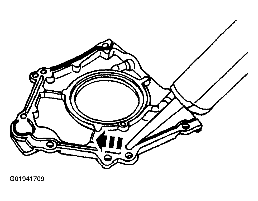
  4. NOTE: If not secured within four minutes, sealant must be removed and sealing area cleaned with metal surface cleaner. Allow to dry until there is no sign of wetness, or four minutes, whichever is longer. Failure to follow this procedure can cause future oil leakage.
    Fig 1: Applying Sealant Around Rear Oil Seal Retainer Sealing Surface
    G01941709Courtesy of FORD MOTOR CO.
  5. Apply a bead of sealant around the rear oil seal retainer sealing surface.
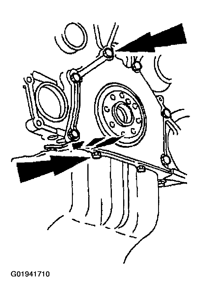
  6. Install the crankshaft rear oil seal retainer and bolts.
    Fig 2: Identifying Crankshaft Rear Oil Seal Retainer Bolts
    G01941710Courtesy of FORD MOTOR CO.
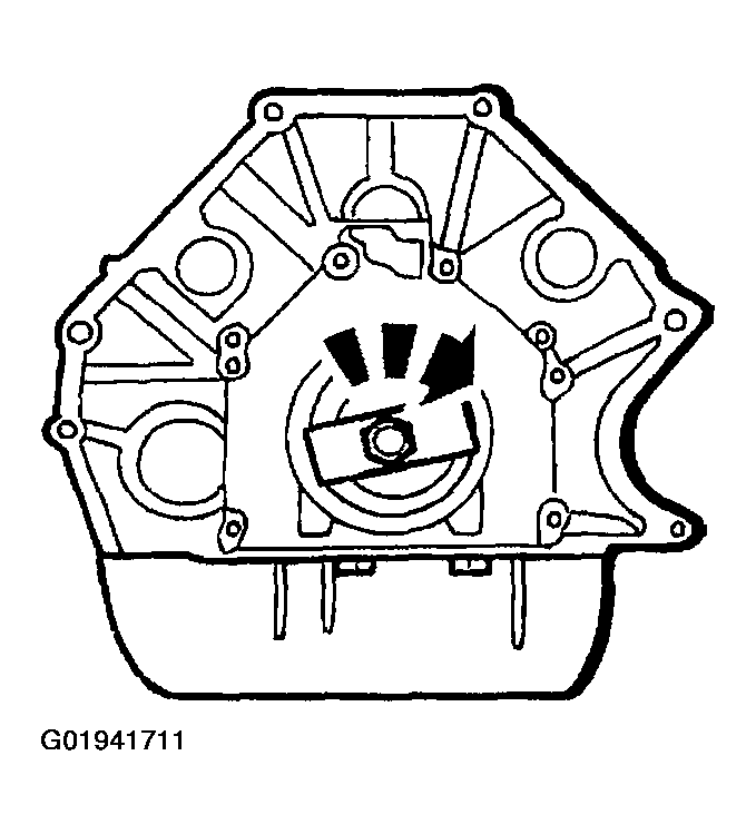
  7. Install a new crankshaft rear oil seal.
    Fig 3: Installing Crankshaft Rear Oil Seal
    G01941711Courtesy of FORD MOTOR CO.
  8. Install the crankshaft oil slinger.
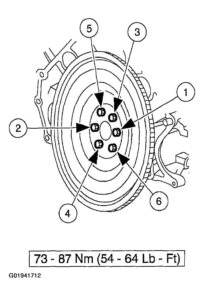
  9. Install the flywheel and the bolts. Tighten the bolts in the sequence shown.
    Fig 4: Identifying Flywheel Bolt Tightening Sequence
    G01941712Courtesy of FORD MOTOR CO.
  10. Support and position the transmission.
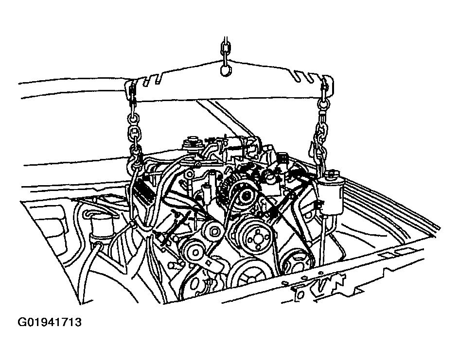
  11. Install the engine assembly in the vehicle.
    Fig 5: Installing Engine Assembly In Vehicle
    G01941713Courtesy of FORD MOTOR CO.
  12. Raise the vehicle.
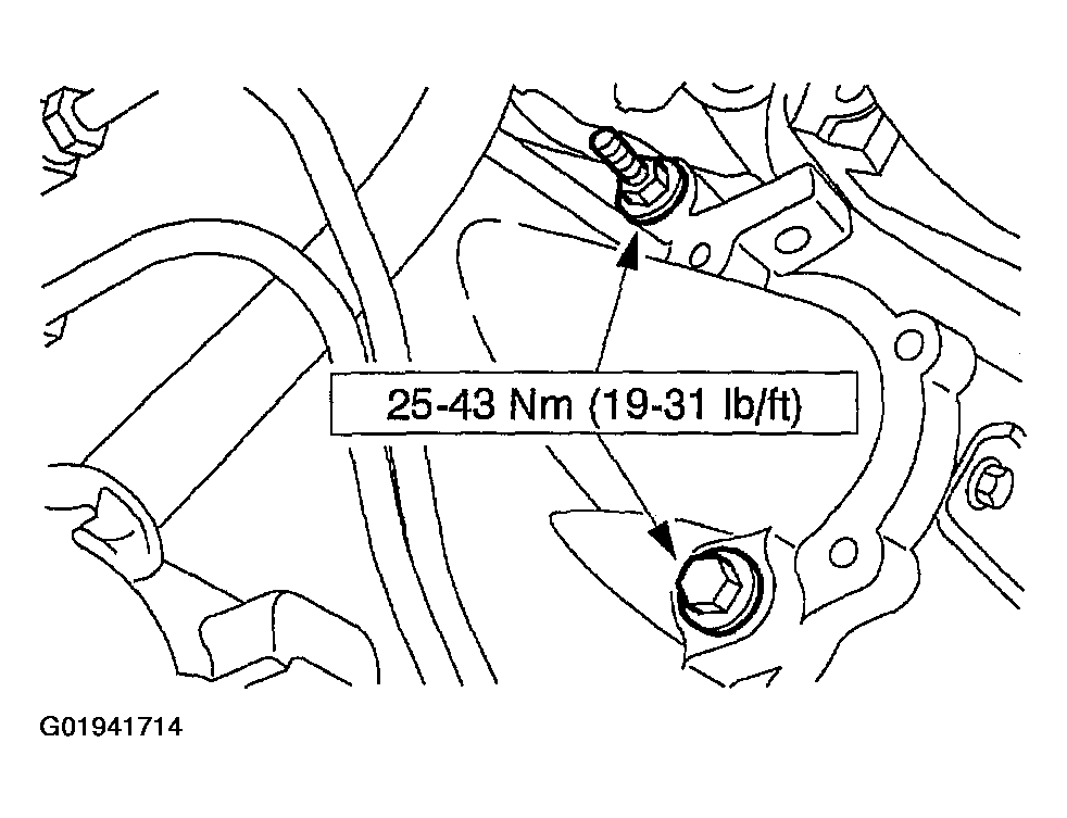
  13. NOTE: When vehicle is raised verify that the torque converter is correctly seated and the index-marks made during removal are lined up.
    Fig 6: Tightening Bolts & Stud
    G01941714Courtesy of FORD MOTOR CO.
  14. Install the five bolts and one stud.
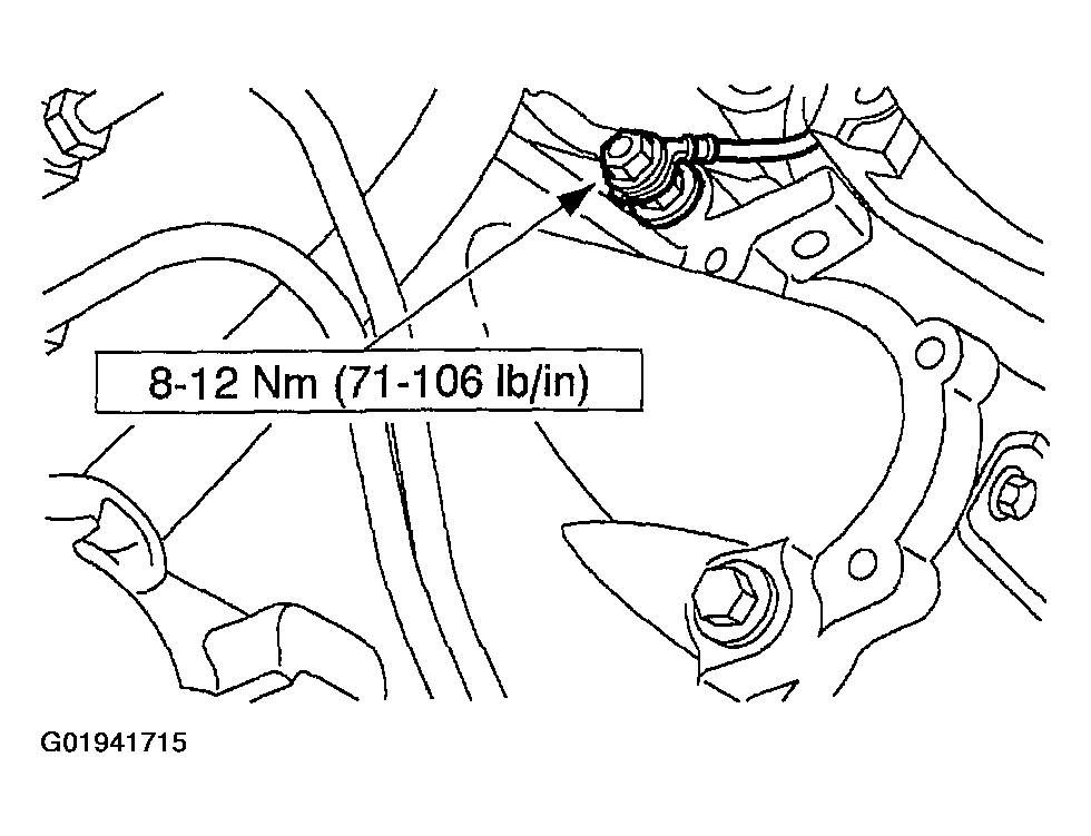
  15. Install the ground wire and the nut.
    Fig 7: Tightening Ground Wire & Nut
    G01941715Courtesy of FORD MOTOR CO.
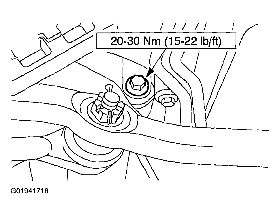
  16. Install the RH bolt.
    Fig 8: Tightening RH Motor Mount Bolt
    G01941716Courtesy of FORD MOTOR CO.
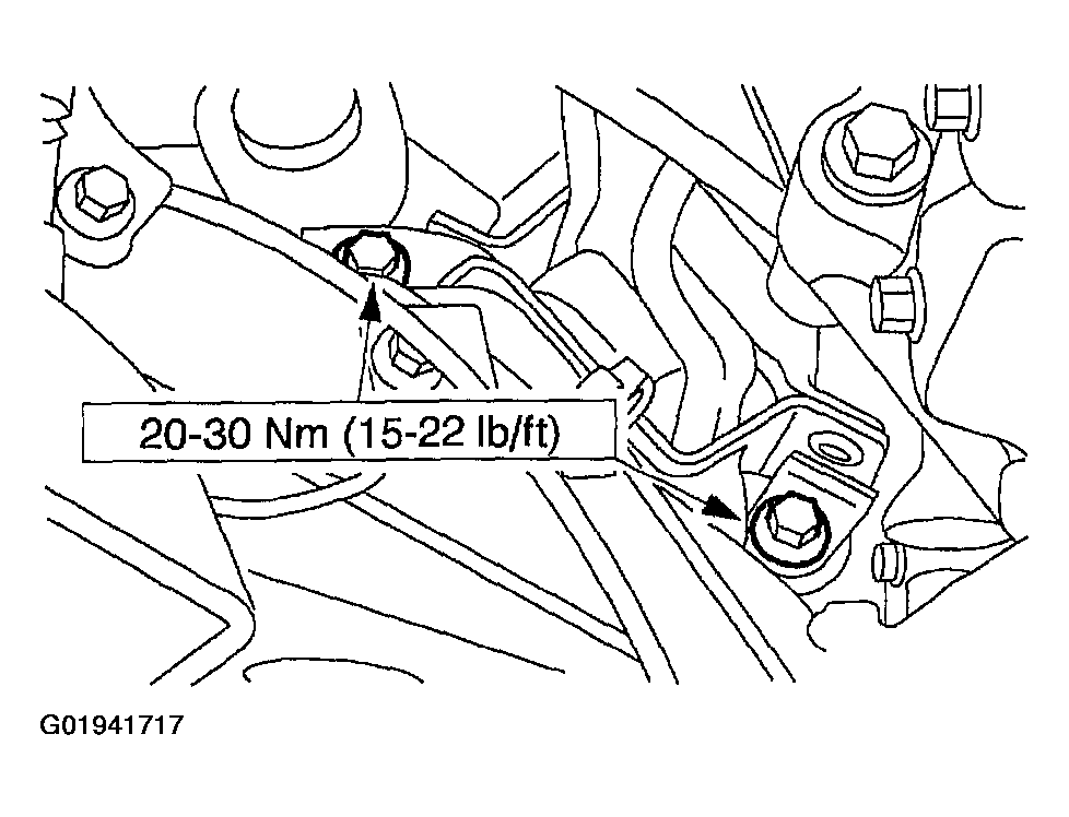
  17. Install the LH bolts.
    Fig 9: Tightening LH Motor Mount Bolts
    G01941717Courtesy of FORD MOTOR CO.
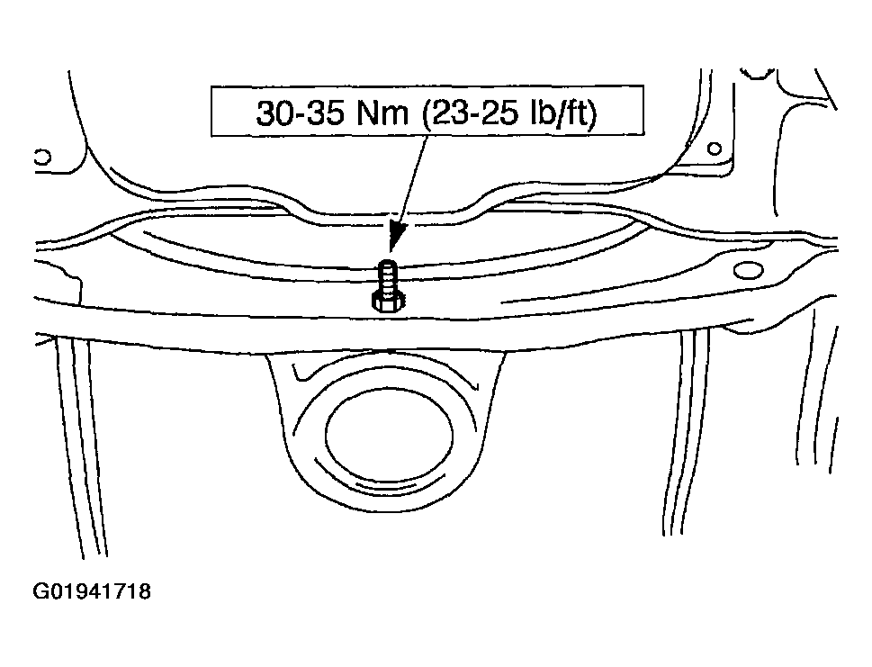
  18. Install the four nuts through the torque converter access panel.
    Fig 10: Tightening Flywheel Nuts
    G01941718Courtesy of FORD MOTOR CO.
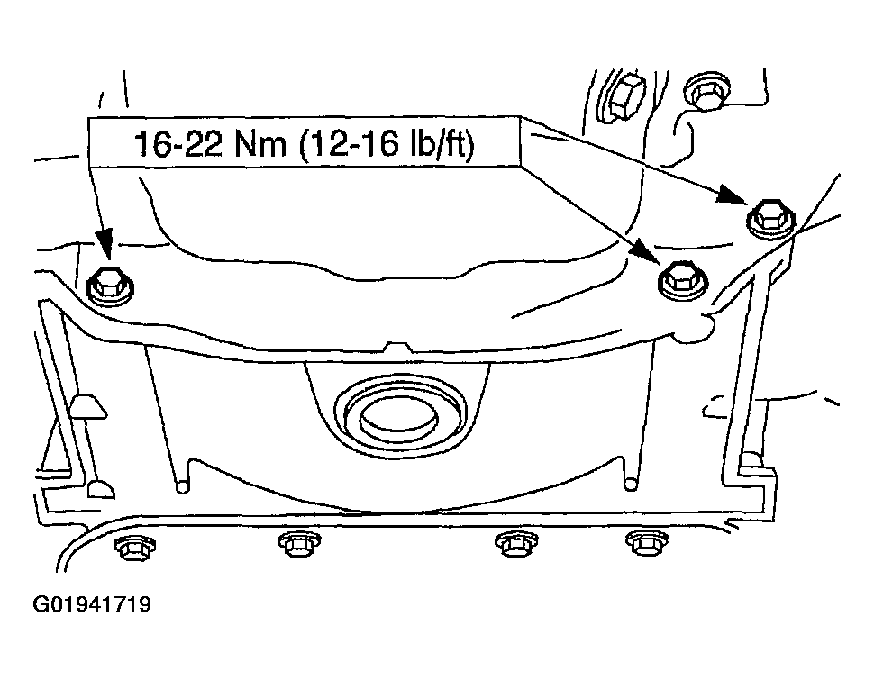
  19. Install the inspection cover and the bolts.
    Fig 11: Tightening Inspection Cover Bolts
    G01941719Courtesy of FORD MOTOR CO.
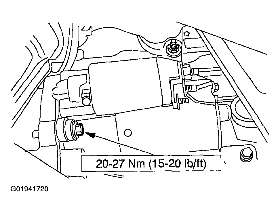
  20. Install the starter motor (11002) and install the bolts.
    Fig 12: Tightening Starter Motor Bolts
    G01941720Courtesy of FORD MOTOR CO.
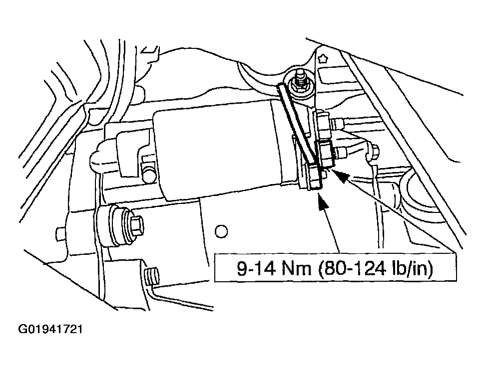
  21. Connect the starter electrical connections and install the nuts.
    Fig 13: Tightening Starter Electrical Connection Nuts
    G01941721Courtesy of FORD MOTOR CO.
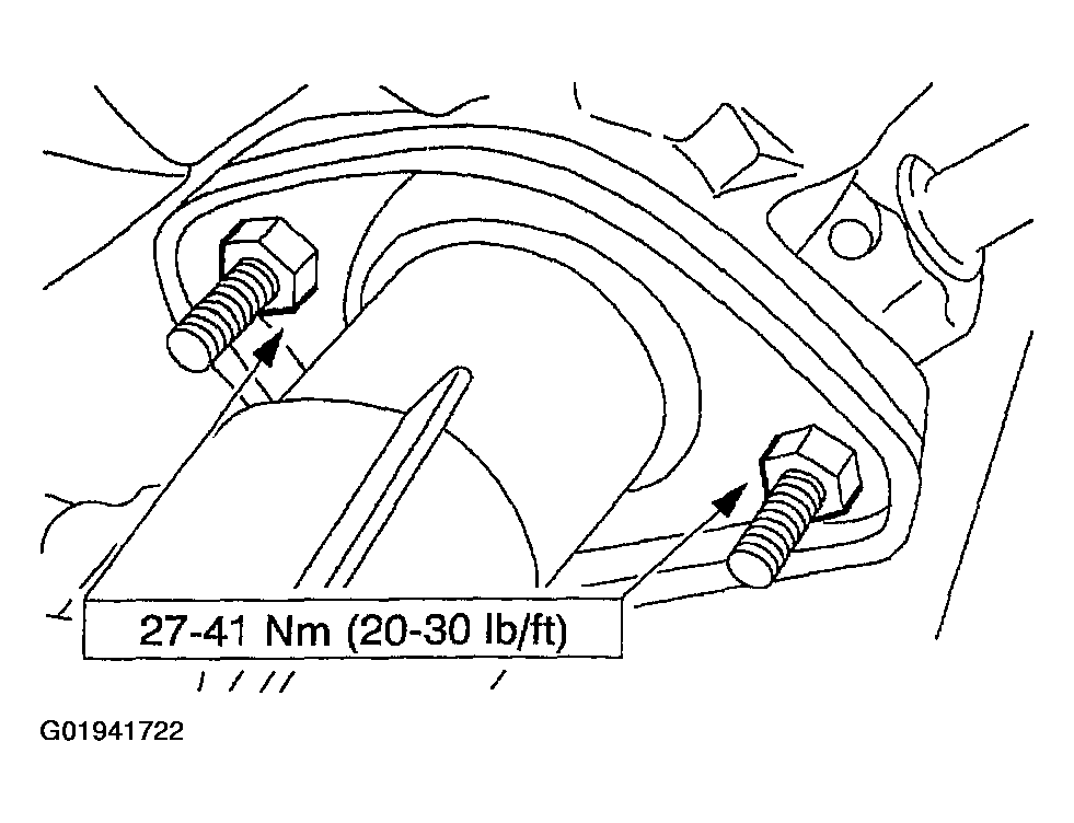
  22. Position the exhaust and install the four nuts.
    Fig 14: Tightening Exhaust Manifold Flange Nuts
    G01941722Courtesy of FORD MOTOR CO.
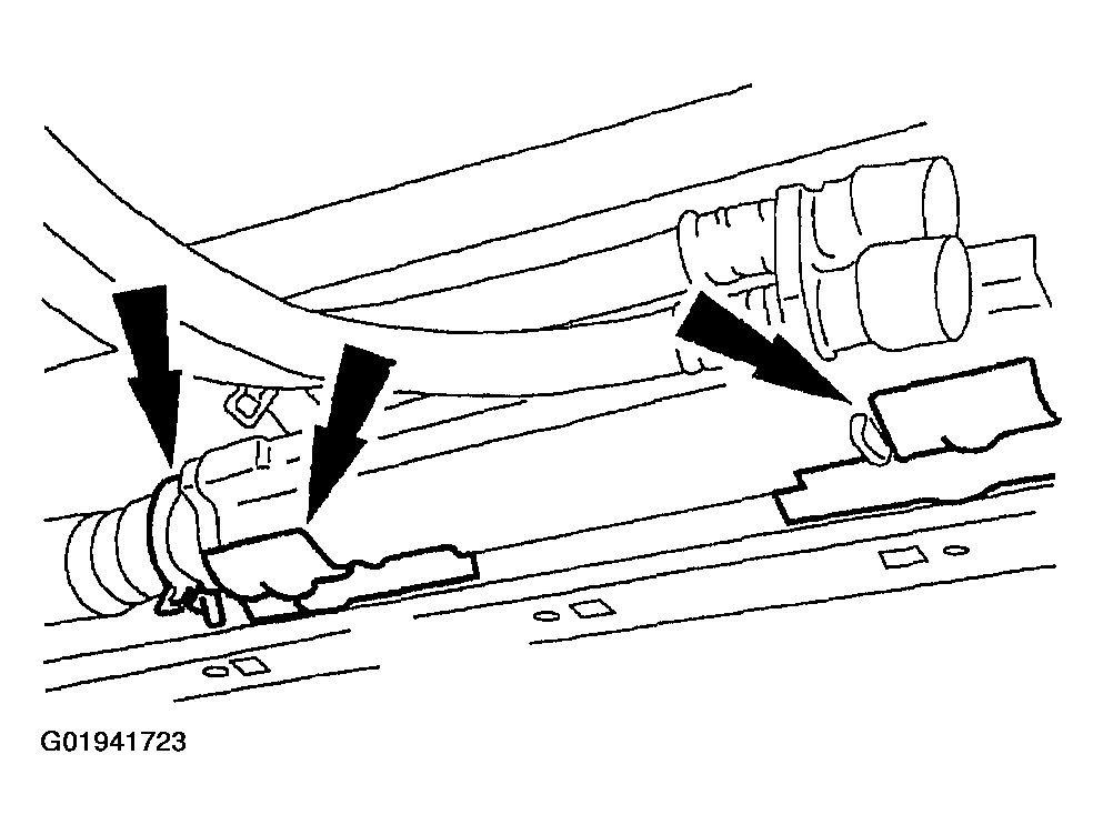
  23. NOTE: Flush the oil cooler with parts cleaner. If metal particles are present in the oil cooler, install a new cooler and hoses.
    NOTE: Some vehicles are not equipped with an oil cooler.
    Fig 15: Identifying Oil Cooler Hoses
    G01941723Courtesy of FORD MOTOR CO.
  24. Connect the two coolant hoses, position the clamp and install the oil cooler.
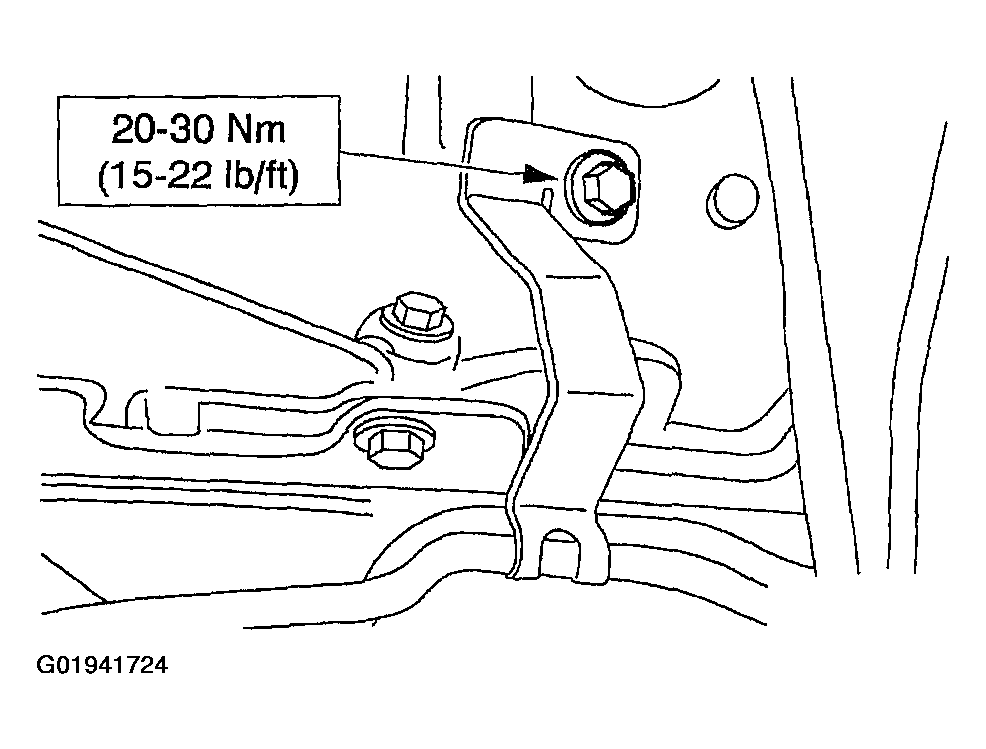
  25. Position the transmission oil cooler lines and install the bolt.
    Fig 16: Tightening Transmission Oil Cooler Line Bracket Bolt
    G01941724Courtesy of FORD MOTOR CO.
  26. Lower the vehicle.
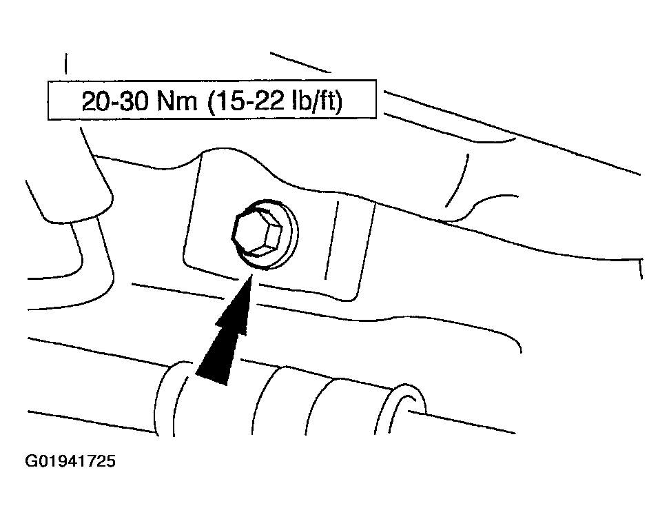
  27. Install the bolt.
    Fig 17: Tightening Bracket Bolt
    G01941725Courtesy of FORD MOTOR CO.
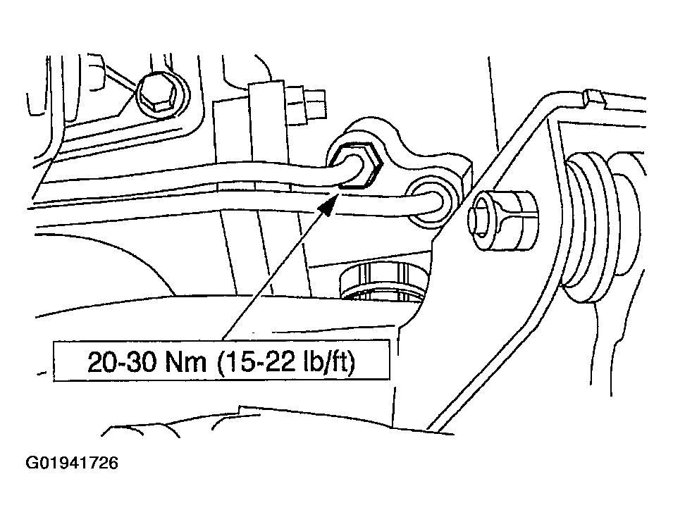
  28. Connect the PSP hose.
    Fig 18: Tightening PSP Hose
    G01941726Courtesy of FORD MOTOR CO.
  29. Connect heated oxygen sensor and position the transmission harness retention clip on the stud.
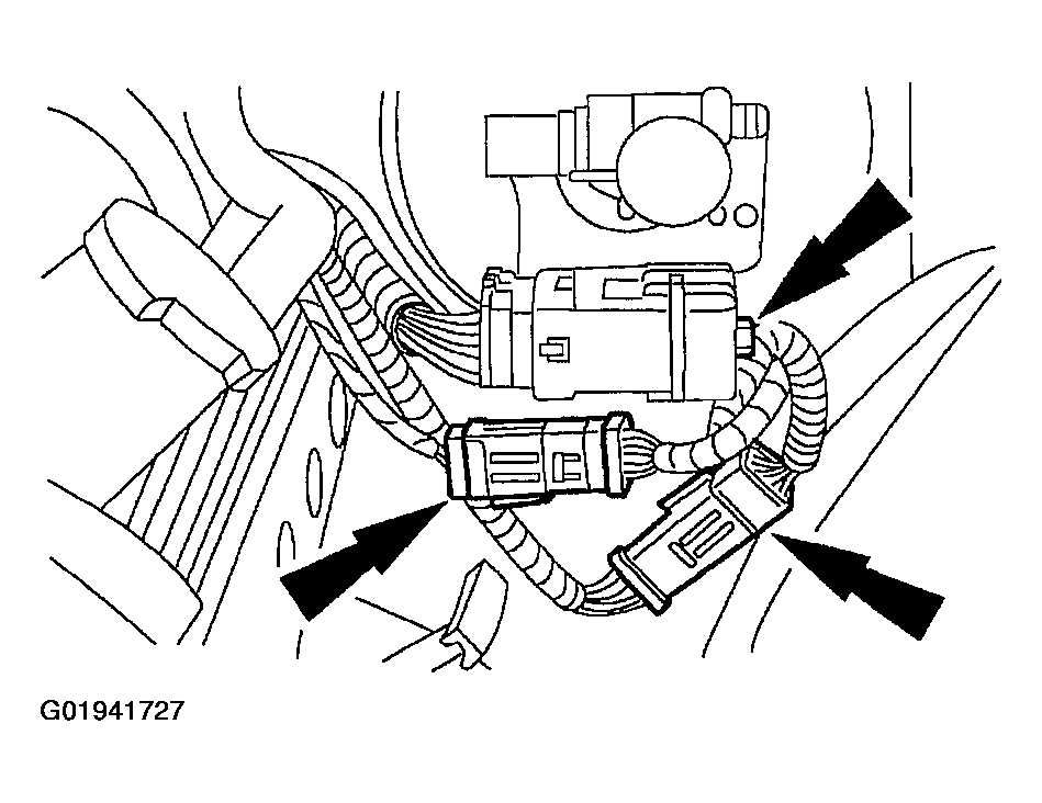
  30. Connect the engine bulkhead connectors.
    Fig 19: Identifying Engine Bulkhead Connectors
    G01941727Courtesy of FORD MOTOR CO.
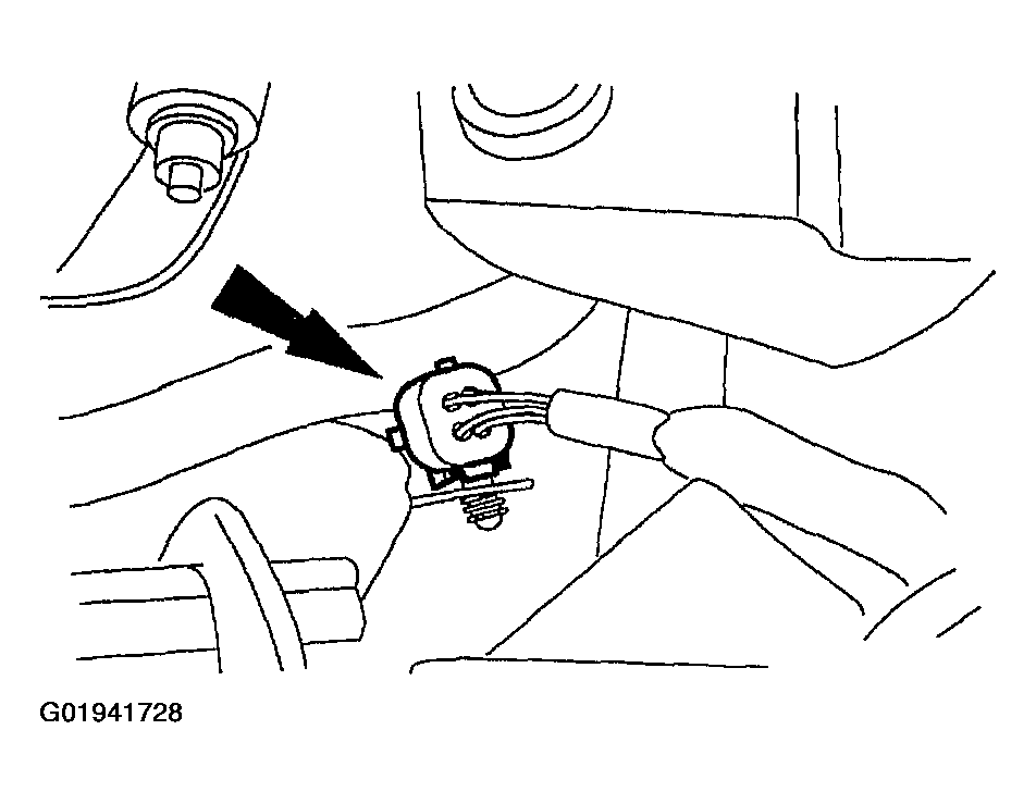
  31. Connect the RH heated oxygen sensor electrical connector and snap into the transmission oil level indicator tube.
    Fig 20: Identifying RH Heated Oxygen Sensor Electrical Connector
    G01941728Courtesy of FORD MOTOR CO.
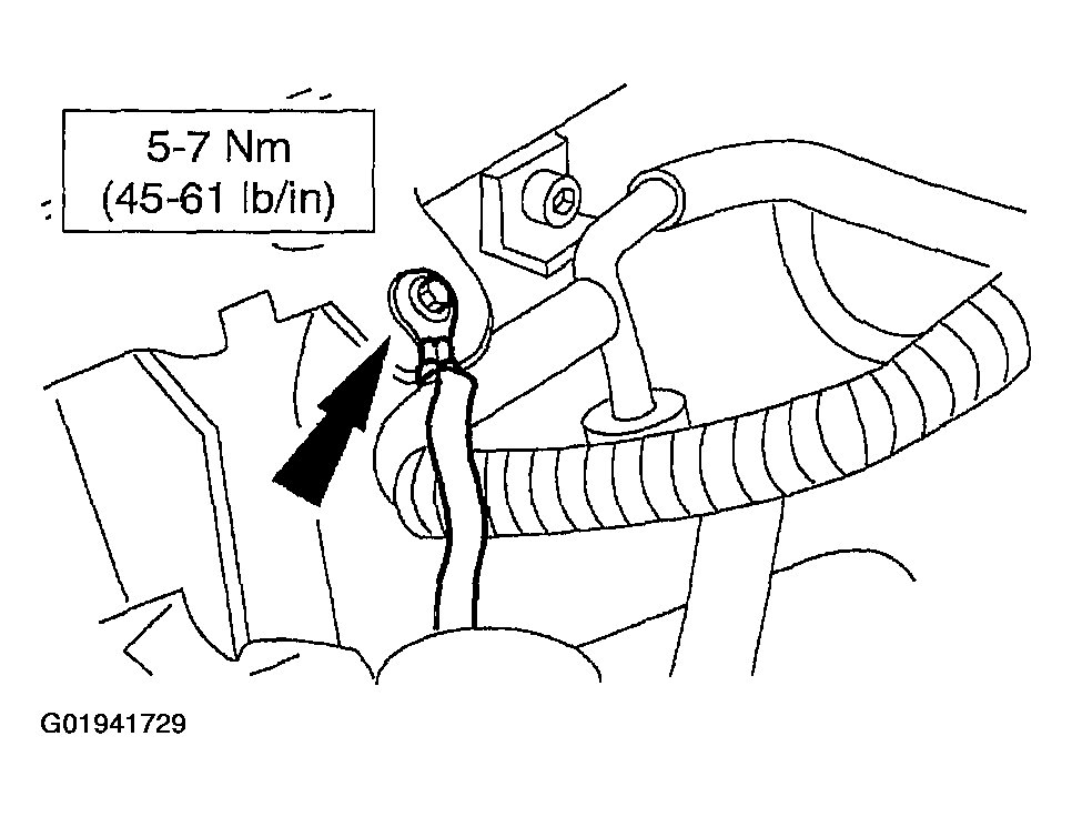
  32. Position the ground strap and install the bolt.
    Fig 21: Tightening Ground Strap Bolt
    G01941729Courtesy of FORD MOTOR CO.
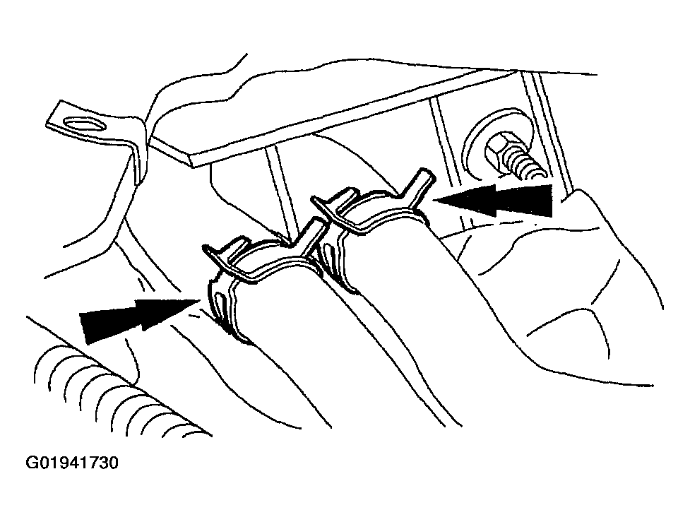
  33. Connect the heater water hoses.
    Fig 22: Identifying Heater Hoses
    G01941730Courtesy of FORD MOTOR CO.
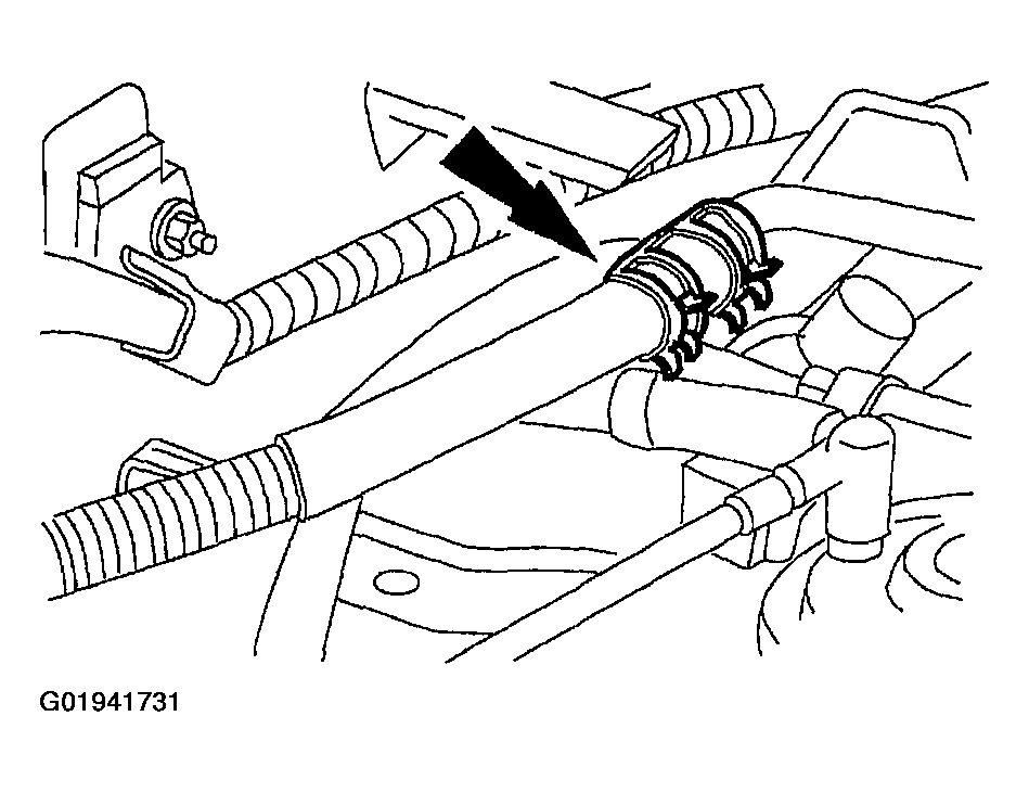
  34. Connect the main vacuum supply hose.
    Fig 23: Identifying Main Vacuum Supply Hose
    G01941731Courtesy of FORD MOTOR CO.

    Gasoline Engines 

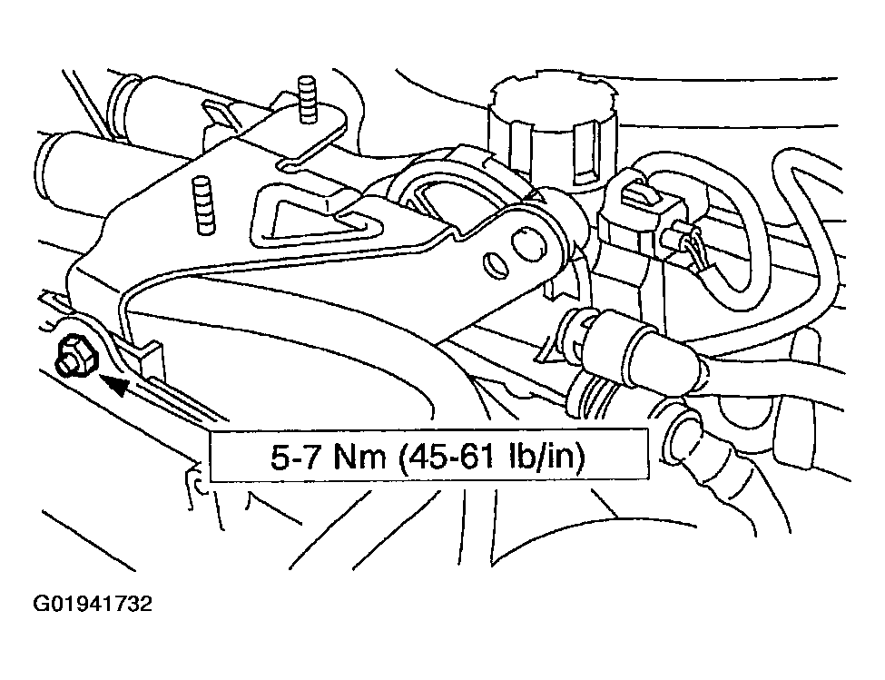
  35. Position the EVAP canister purge valve and install the nut.
    Fig 24: Tightening EVAP Canister Purge Valve Nut
    G01941732Courtesy of FORD MOTOR CO.
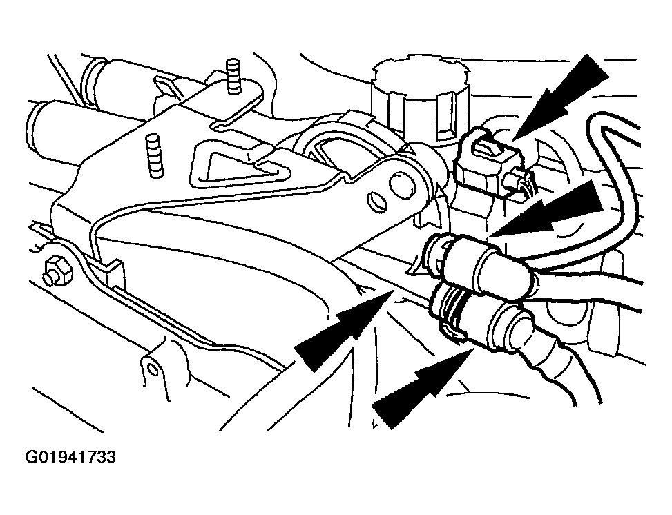
  36. Connect the three hoses and the EVAP canister purge valve electrical connection.
    Fig 25: Identifying EVAP Canister Purge Valve Electrical Connection & Hoses
    G01941733Courtesy of FORD MOTOR CO.
  37. Position the accelerator cable and the speed control actuator cable and install in the clips.
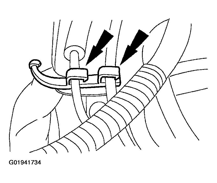
    Fig 26: Identifying Accelerator Cable & Speed Control Actuator Cable Clips
    G01941734Courtesy of FORD MOTOR CO.

    All Engines 

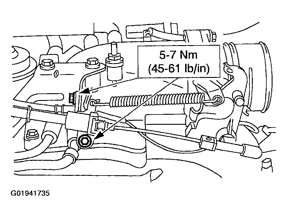
  38. Connect the accelerator cable and the speed control actuator cable:
    • Install the bolts.
    • Connect the cables.
    Fig 27: Connecting Accelerator Cable & Speed Control Actuator Cable
    G01941735Courtesy of FORD MOTOR CO.
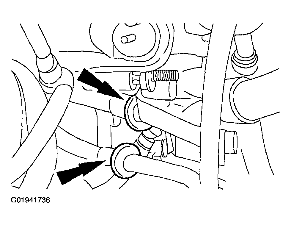
  39. Connect the air conditioning lines.
    Fig 28: Identifying Air Conditioning Lines
    G01941736Courtesy of FORD MOTOR CO.
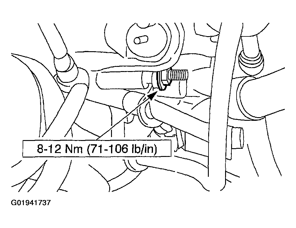
  40. Install the nut and the A/C line bracket.
    Fig 29: Tightening A/C Line Bracket Nut
    G01941737Courtesy of FORD MOTOR CO.
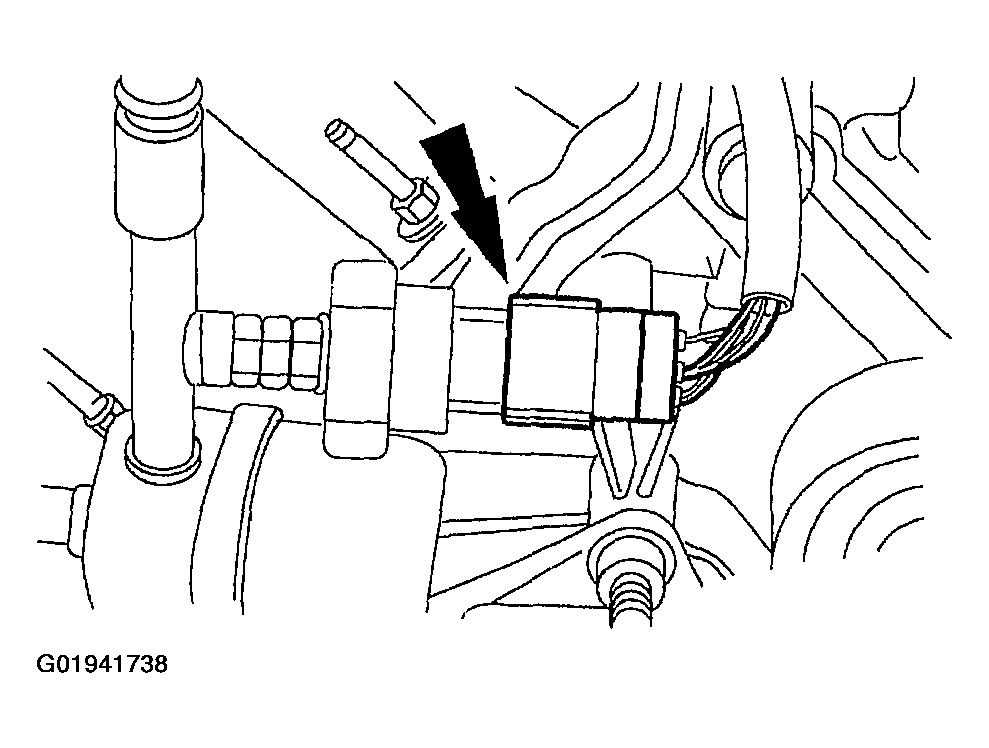
  41. Connect the A/C cycling switch electrical connector.
    Fig 30: Identifying A/C Cycling Switch Electrical Connector
    G01941738Courtesy of FORD MOTOR CO.

    Gasoline Engines 

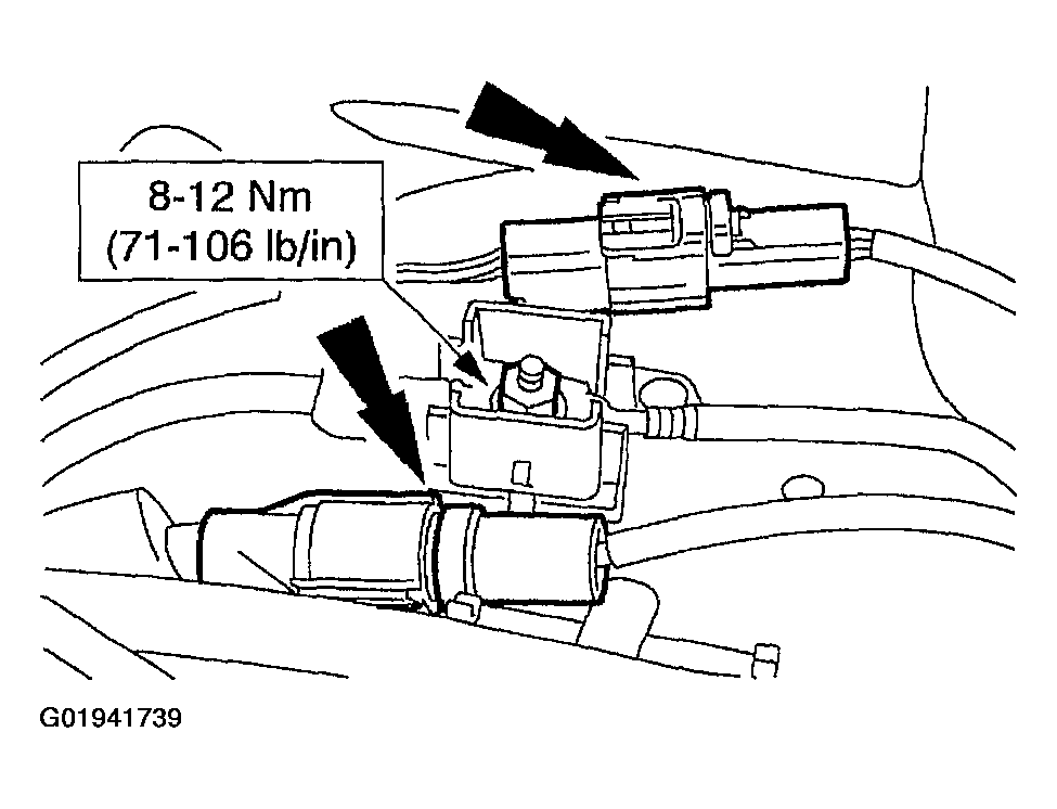
  42. Position the wire and install the nut; connect the electrical connections at the RH inner fender.
    Fig 31: Identifying RH Inner Fender Nut & Electrical Connections
    G01941739Courtesy of FORD MOTOR CO.

    Natural Gas Engines 

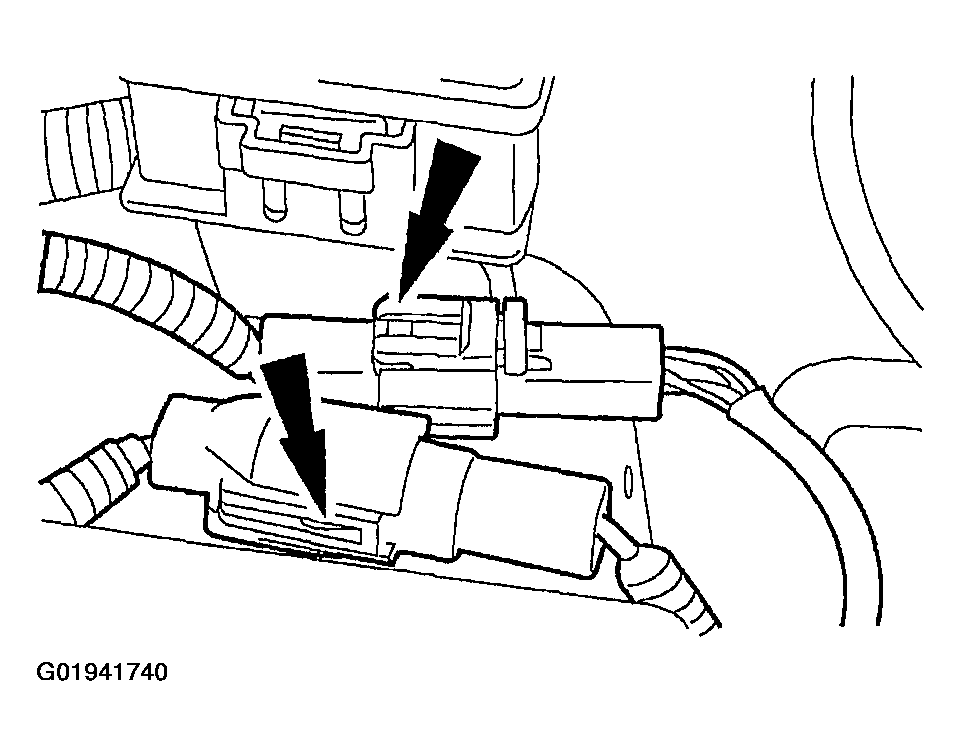
  43. Connect the connectors.
    Fig 32: Identifying Electrical Connections
    G01941740Courtesy of FORD MOTOR CO.
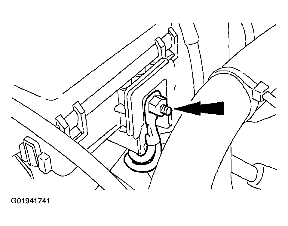
  44. Install the wires.
    Fig 33: Identifying Power Distribution Box Nut
    G01941741Courtesy of FORD MOTOR CO.
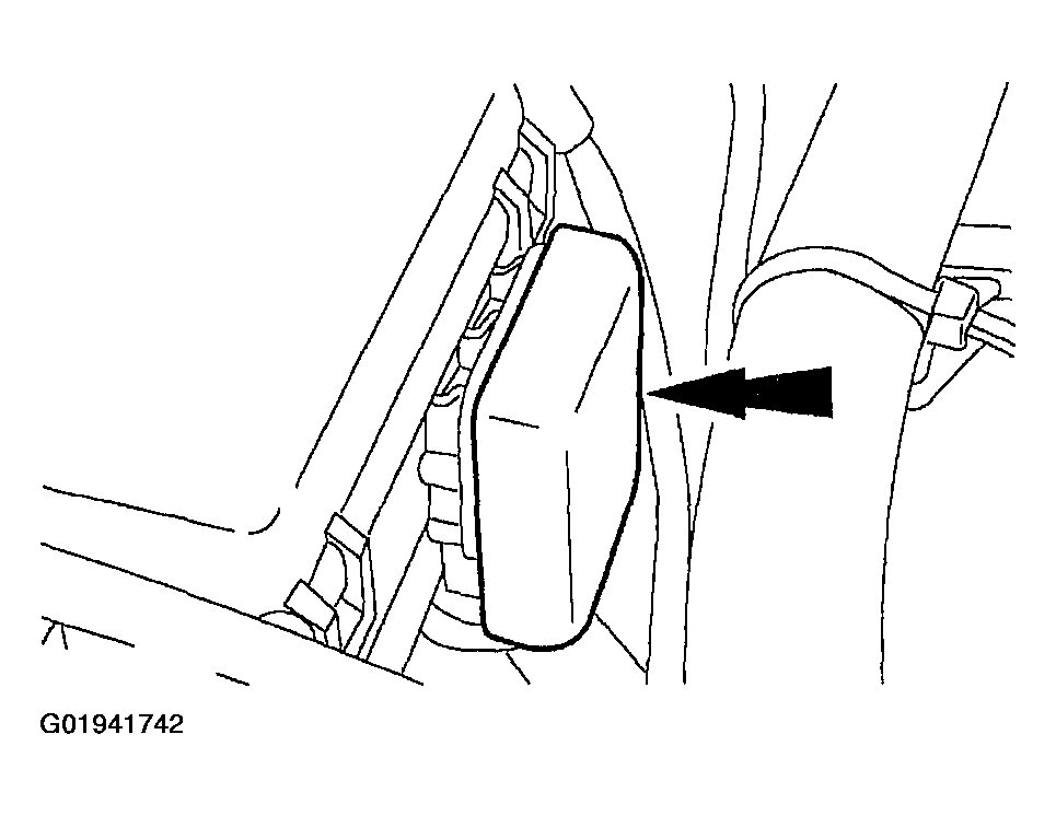
  45. Install the cover.
    Fig 34: Identifying Power Distribution Box Cover
    G01941742Courtesy of FORD MOTOR CO.

    All Engines 

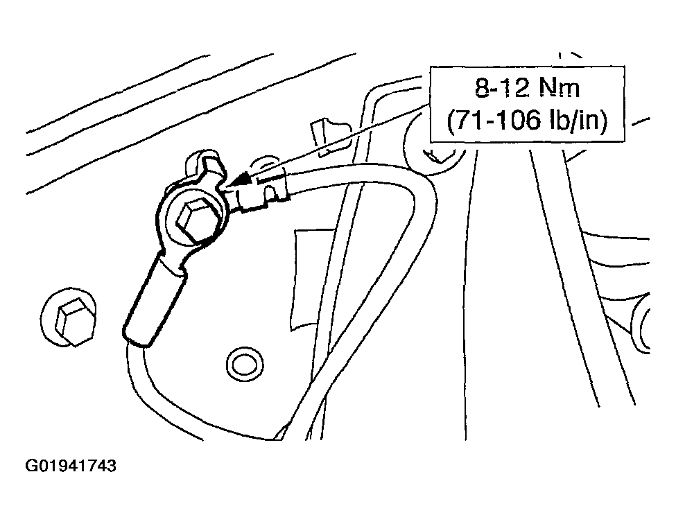
  46. Position the ground wires and install the bolt.
    Fig 35: Tightening Ground Wire Nut
    G01941743Courtesy of FORD MOTOR CO.
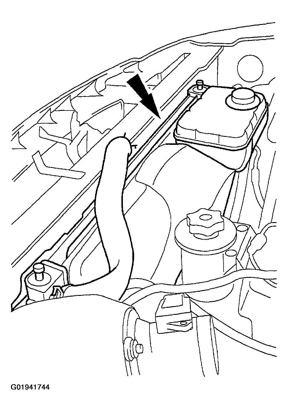
  47. Install the radiator assembly.
    Fig 36: Identifying Radiator Assembly
    G01941744Courtesy of FORD MOTOR CO.
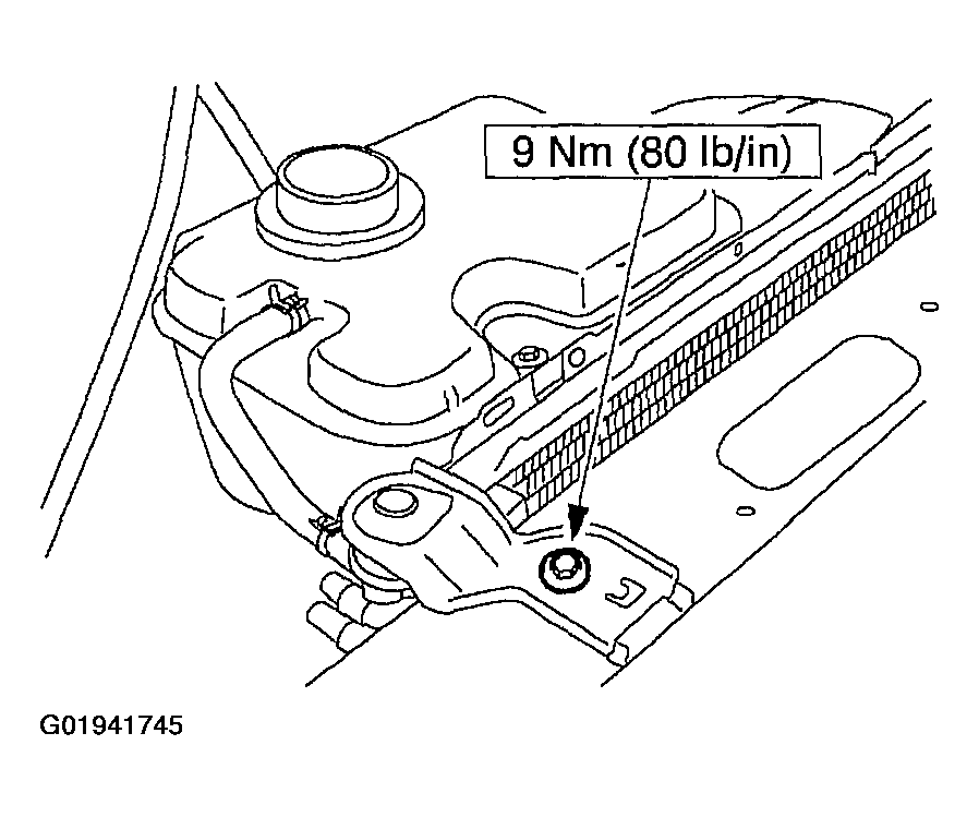
  48. Install the brackets and the bolts.
    Fig 37: Tightening Radiator Mounting Bracket Bolt
    G01941745Courtesy of FORD MOTOR CO.
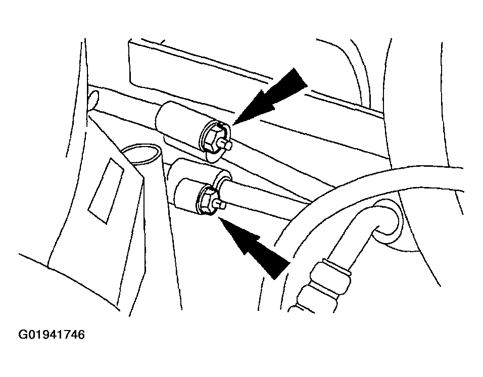
  49. Connect the lines to the A/C condenser core and install the nuts.
    Fig 38: Identifying A/C Condenser Core Line Nuts
    G01941746Courtesy of FORD MOTOR CO.
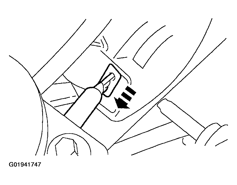
  50. Connect the fan motor.
    Fig 39: Identifying Cooling Fan Electrical Connector
    G01941747Courtesy of FORD MOTOR CO.
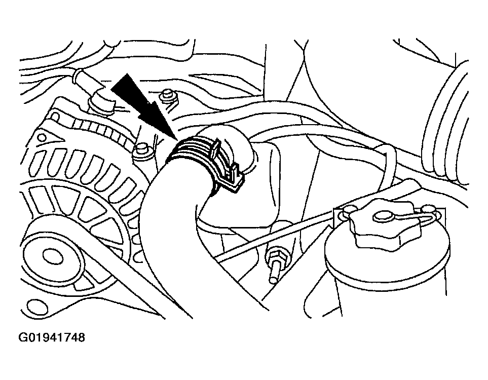
  51. Connect the upper radiator hose to the water outlet adapter.
    Fig 40: Identifying Upper Radiator Hose
    G01941748Courtesy of FORD MOTOR CO.
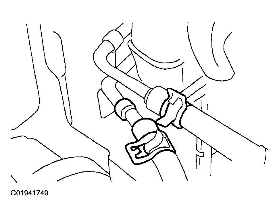
  52. Connect the hoses to the power steering fluid cooler.
    Fig 41: Identifying Power Steering Fluid Cooler Hoses
    G01941749Courtesy of FORD MOTOR CO.
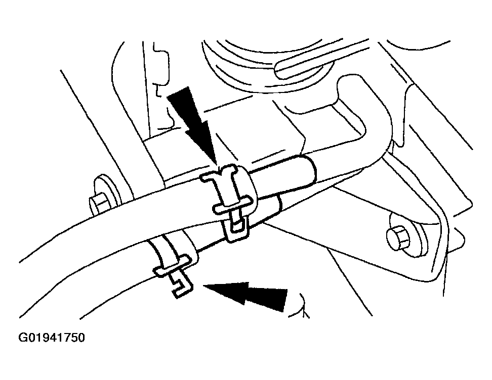
  53. Connect the hoses to the transmission fluid cooler.
    Fig 42: Identifying Transmission Fluid Cooler Hoses
    G01941750Courtesy of FORD MOTOR CO.
  54. Install the radiator upper sight shield.
  55. Install the battery.
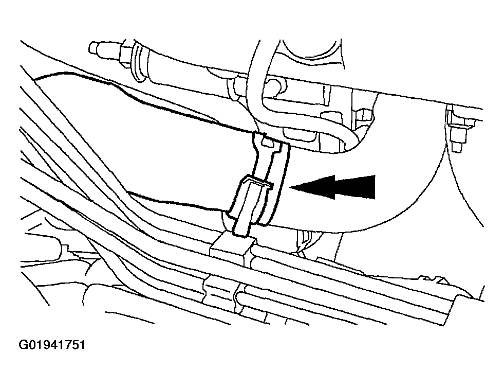
  56. Connect the lower radiator hose to the oil filter adapter.
    Fig 43: Identifying Lower Radiator Hose
    G01941751Courtesy of FORD MOTOR CO.
  57. Install the air cleaner outlet tube.
  58. Install the wiper mounting arm and pivot shaft. For additional information, refer to WIPER MOTOR .
  59. Fill the crankcase with clean engine oil.
  60. Fill and bleed the cooling system.
  61. Fill the power steering system.
  62. Evacuate and recharge the air conditioning system. For additional information, refer to AIR CONDITIONING (A/C) SYSTEM RECOVERY, EVACUATION & CHARGING .
  63. Install the hood.