Starter Does Not Crank
- The PATS system DTCs are the only DTCs of concern in this step. Only repair retrieved non-PATS DTCs if a customer concern is reported. Perform the Powertrain Control Module (PCM) self-test. See SELF-DIAGNOSTIC SYSTEM in PASSIVE ANTI-THEFT SYSTEMS - CROWN VICTORIA & GRAND MARQUIS article in DOOR LOCKS & ANTITHEFT SYSTEMS in ACCESSORIES & EQUIPMENT. If any PATS DTCs are retrieved, repair as necessary. See DIAGNOSTIC TESTS in PASSIVE ANTI-THEFT SYSTEMS - CROWN VICTORIA & GRAND MARQUIS article in DOOR LOCKS & ANTITHEFT SYSTEMS in ACCESSORIES & EQUIPMENT. If no, go to next step.
- Verify battery condition. Battery voltage should be 12 volts or more. Load test battery at approximately one-half cold cranking amperage rating. See load tester manufacturer's instructions. If battery voltage is less than 12 volts or loaded battery voltage is less than 9.6 volts, service battery or charging system as necessary. If battery is okay, go to next step.
- Measure voltage between positive battery terminal and negative cable connection at engine block. If battery voltage is present, go to next step. If battery voltage is not present, replace ground cable or repair ground connections.
- Measure voltage between positive battery terminal and starter motor case. If battery voltage is present, go to next step. If battery voltage is not present, remove starter motor and clean mounting surface. See STARTER MOTOR under REMOVAL & INSTALLATION. Install starter and check system for normal operation.
- Turn ignition off. Measure voltage between starter solenoid terminal "B" (battery cable) and ground. If battery voltage is present, go to next step. If battery voltage is not present, replace battery positive cable and check system for normal operation.
- Momentarily connect jumper wire between starter solenoid terminal "B" (battery cable) and terminal "S" (Yellow/Light Blue wire). If starter motor cranks engine, go to next step. If starter motor does not crank engine, replace starter motor. See STARTER MOTOR under REMOVAL & INSTALLATION.
- Disconnect harness connector from starter solenoid terminal "S" (Yellow/Light Blue wire). Measure voltage between starter solenoid connector (Yellow/Light Blue wire) and ground with ignition switch in START position. If battery voltage is not present, go to next step. If battery voltage is present, clean starter solenoid "S" terminal and connector. Check for loose or intermittent connection. Repair as necessary and check system for normal operation.
- Turn ignition off. Remove starter relay. Measure voltage between starter relay harness connector terminal No. 86 and ground with ignition switch in START position. See Fig 1. If battery voltage is present, go to next step. If battery voltage is not present, go to step 13.
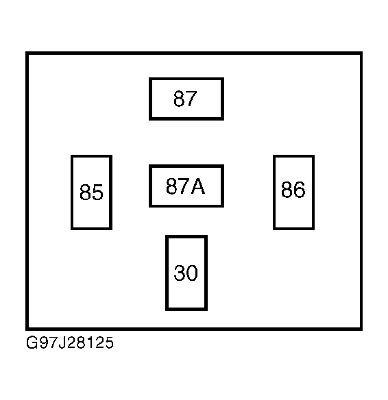 Courtesy of FORD MOTOR CO.
- Turn ignition off. Measure voltage between starter relay connector terminal No. 30 and ground. If battery voltage is present, go to next step. If battery voltage is not present, check battery junction box fuse No. 2 (30-amp). If fuse is okay, repair Yellow wire between relay and fuse. Check system for normal operation. See WIRING DIAGRAMS .
- Measure resistance between starter relay connector terminal No. 85 and ground. If resistance is less than 5 ohms, go to next step. If resistance is 5 ohms or greater, repair Black ground wire between relay connector and ground connection on right fender, near battery. Check system for normal operation.
- Disconnect starter solenoid "S" terminal connector (Yellow/Light Blue wire). Measure resistance between starter relay connector terminal No. 87 and ground. If resistance is greater than 10,000 ohms, go to next step. If resistance is 10,000 ohms or less, repair short to ground in Yellow/Light Blue wire. Check system for normal operation.
- Measure resistance between starter relay connector terminal No. 87 and starter solenoid terminal "S" (Yellow/Light Blue wire). If resistance is less than 5 ohms, install new starter relay and check system for normal operation. If resistance is 5 ohms or greater, repair open in Yellow/Light Blue wire between starter and relay. See WIRING DIAGRAMS .
- Measure voltage at both sides of battery junction box fuse No. 2 (30-amp) and ground. If battery voltage is present at both sides of fuse and ground, go to step 15. If battery voltage is not present between both sides of fuse and ground, go to next step.
- Remove and inspect battery junction box fuse No. 2 (30-amp). If fuse is okay, go to step 16. If fuse is blown, measure resistance between fuse No. 2 input cavity and ground. If resistance is more than 10,000 ohms, install new fuse and check for normal system operation. If resistance is 10,000 ohms or less, check for short to ground in Red wire or Gray wire between battery and battery junction box. Check Gray fusible links. Repair as necessary and check system for normal operation.
- Disconnect ignition switch harness connector. Measure voltage between ignition switch harness connector terminal B4 and ground. See Fig 2. If battery voltage is present, go to step 17. If battery voltage is not present, repair Yellow wire between fuse and ignition switch. See WIRING DIAGRAMS .
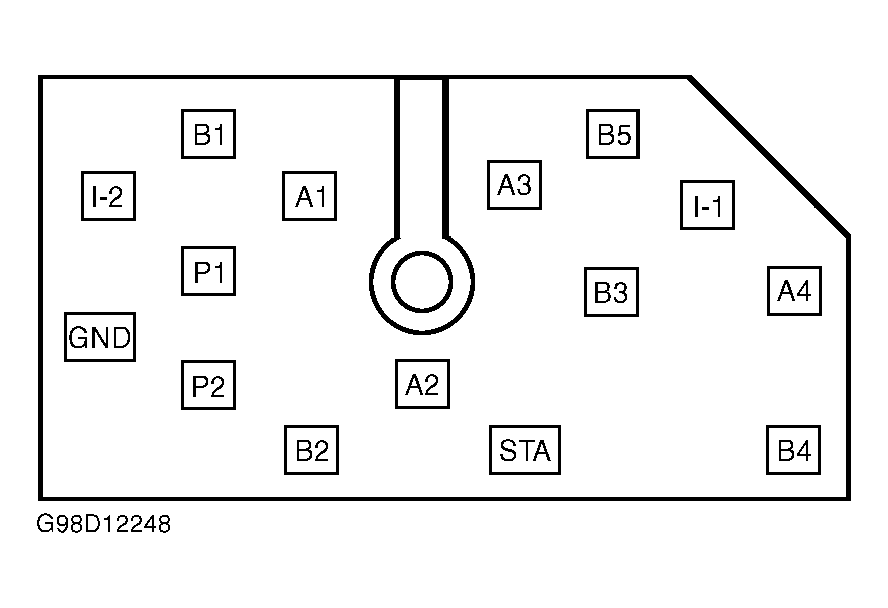 Courtesy of FORD MOTOR CO.
- Check for open in Red or Gray wires between battery and battery junction box, or Gray fusible links. Repair as necessary and check system for normal operation.
- Reconnect ignition switch harness connector. Connect negative voltmeter lead to ground. With voltmeter positive lead, backprobe harness connector terminal STA (White/Pink wire). Measure voltage with ignition switch in START position. See Fig 2. If battery voltage is present, go to next step. If battery voltage is not present, inspect connector and ignition switch terminals for looseness or corrosion, and repair as necessary. If connections are okay, test ignition switch. See STEERING COLUMN SWITCHES - CROWN VICTORIA & GRAND MARQUIS article in ACCESSORIES & EQUIPMENT.
- Disconnect Transmission Range (TR) sensor harness connector. Measure voltage between ground and TR sensor harness connector terminal No. 12 (White/Pink wire) with ignition switch in START position. See Fig 3. If battery voltage is present, go to next step. If battery voltage is not present, repair White/Pink wire between ignition switch and TR sensor. See WIRING DIAGRAMS .
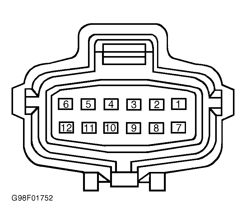 Courtesy of FORD MOTOR CO.
- Reconnect TR sensor connector. Ensure transmission is in Park or Neutral. With voltmeter positive lead, backprobe TR sensor connector terminal No. 10 (Red/Light Blue wire). Measure voltage between connector terminal No. 10 and ground with ignition switch in START position. If battery voltage is present, go to next step. If battery voltage is not present, inspect connector and sensor for loose or corroded connections. If connections are okay, check shift linkage adjustment. See SHIFT LINKAGE under ADJUSTMENTS. If shift linkage is okay, check TR sensor adjustment. See TRANSMISSION RANGE SENSOR under ADJUSTMENTS. If TR sensor adjustment is okay, replace TR sensor and check system for normal operation.
- Disconnect TR sensor connector. Measure resistance of Red/Light Blue wire between TR sensor connector terminal No. 10 and starter relay connector terminal No. 86 in high current relay center. See Fig 1 and Fig 3
. If resistance is 5 ohms or greater, repair Red/Light Blue wire. See WIRING DIAGRAMS . If resistance is less than 5 ohms, go to next step.
- Disconnect TR sensor connector. Measure resistance between TR sensor connector terminal No. 10 (Red/Light Blue wire) and ground. See Fig 3. If resistance is less than 10,000 ohms, repair short to ground in Red/Light Blue wire. If resistance is 10,000 ohms or greater, problem is intermittent. Reconnect all connectors and check system for normal operation.