Test C: Reference Voltage: Testing
WARNING: This page is about a different variant/trim than selected.
- 1) Check VREF Circuit For Short To PWR In Harness
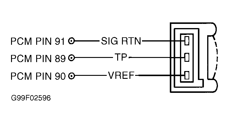
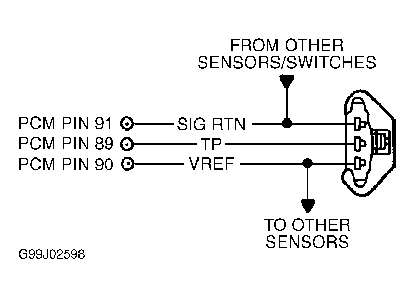
Disconnect TP sensor connector. Turn ignition switch to ON position. Using a DVOM, measure voltage between SIG RTN and VREF circuit terminals at TP sensor harness connector. See Figure-Figure . If VREF voltage is more than 6 volts, check for short to PWR in VREF. Go to step 35). If VREF voltage is 6 volts or less, go to next step. - 2) Check Battery Voltage
Using a DVOM, measure voltage between battery terminals. If battery voltage is more than 10.5 volts, go to next step. If battery voltage is 10.5 volts or less, check charging system and battery and repair as necessary. See appropriate GENERATORS & REGULATORS article in STARTING & CHARGING SYSTEMS. Recharge or replace battery as necessary. - 3) Check Voltage Between B+ & SIG RTN Circuit
Disconnect suspect sensor harness connector. Using a DVOM, measure voltage between SIG RTN terminal at suspect sensor harness connector and positive battery terminal. If voltage measurement is more than 10.5 volts and within one volt of battery voltage, go to next step. If voltage is 10.5 volts or less, a SIG RTN/PWR GND fault is present. Go to step 25). - 4) Check VREF Voltage Through PCM On TP PID
Turn ignition switch to OFF position. Connect scan tool to Data Link Connector (DLC). Using scan tool, access PID/DATA MONITOR & RECORD menu. See PARAMETER IDENTIFICATION MODE under ADDITIONAL SYSTEM FUNCTIONS. Using scan tool, access TP PID from PID/DATA MONITOR & RECORD menu. If scan tool is able to access TP PID, check VREF circuit for open. Go to step 20). If scan tool is unable to access TP PID, go to next step to check VPWR and VREF for shorts. - 5) Check VPWR Voltage To Idle Air Control Valve
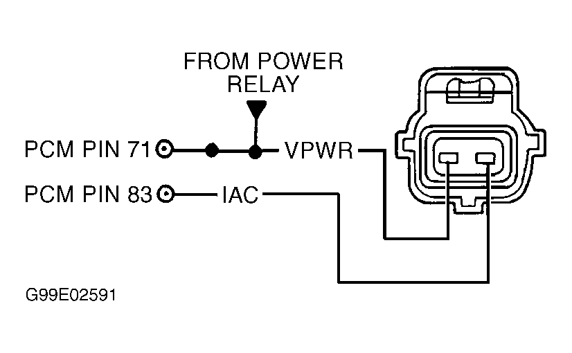
Turn ignition switch to OFF position. Ensure TP sensor is disconnected. Disconnect Idle Air Control (IAC) valve electrical connector. Turn ignition switch to ON position. Using a DVOM, measure voltage between VPWR terminal at IAC harness connector and negative battery terminal. See Fig 1 or Fig 2 . If voltage is 10.5 volts or less, VPWR is not present. Reconnect connectors and go to TEST X, step 1) (Escort and Mustang), or go to TEST B, step 1) (all others). If voltage is more than 10.5 volts, proceed as follows:- On Cougar and Escort 2.0L, Econoline and Pickup 5.4L NGV, go to step 7).
- On all others, go to next step.
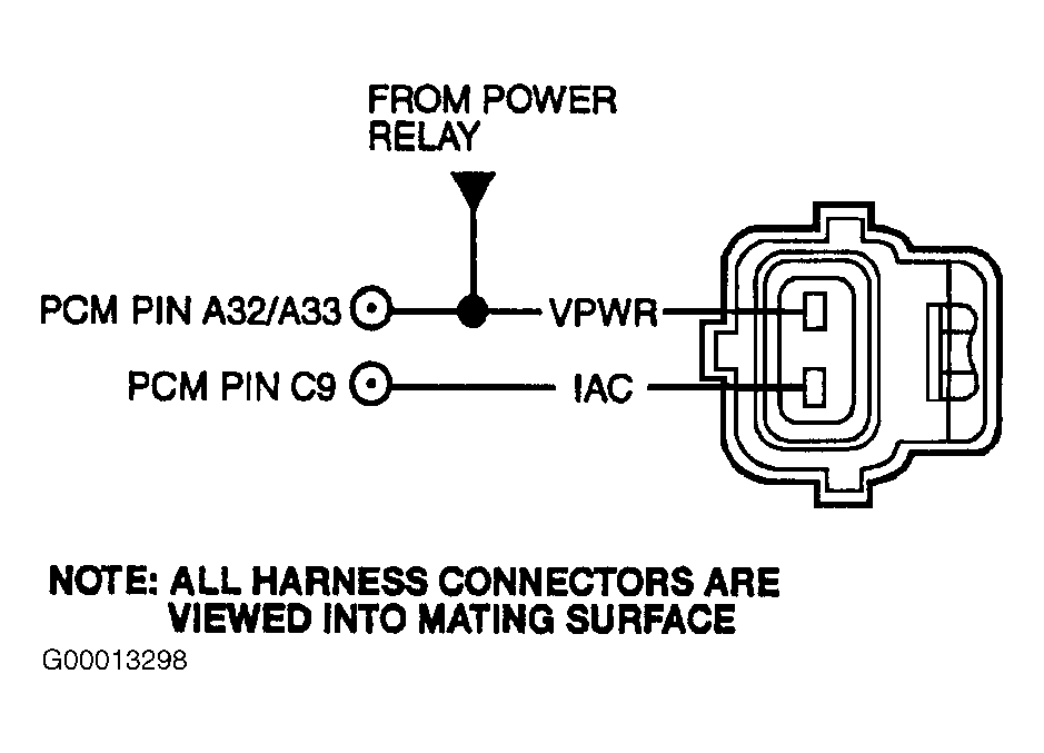 Courtesy of FORD MOTOR CO.
- 6) Check For Short Between VREF Circuit & SIG RTN Circuit In DPFE Or ESM
Ensure TP sensor is disconnected. Disconnect EGR System Module 6-pin harness connector (Ranger 2.3L), or DPFE harness connector (all others). Turn ignition switch to ON position. Using a DVOM, measure voltage between SIG RTN terminal and VREF terminal at TP sensor harness connector. If voltage is 4-6 volts, turn ignition switch to OFF position and replace ESM (Ranger 2.3L) or DPFE sensor (all others). If voltage is not 4-6 volts, proceed as follows:- On Taurus 3.0L Flex Fuel models, go to step 12).
- On all others, go to next step.
- 7) Check For Short Between VREF Circuit & SIG RTN Circuit In FTP Sensor
Ensure TP sensor, DPFE sensor or ESM (if equipped) are disconnected. Disconnect FTP sensor. Turn ignition switch to ON position. Using a DVOM, measure voltage between SIG RTN terminal and VREF terminal at TP sensor harness connector. If voltage is 4-6 volts, turn ignition switch to OFF position and replace FTP sensor. If voltage is not 4-6 volts, proceed as follows: - 8) Check For Short Between VREF Circuit & SIG RTN Circuit In ACP Sensor
Ensure DPFE, ESM (if equipped), TP sensor and FTP sensor (if applicable) are disconnected. Disconnect ACP sensor. Turn ignition switch to ON position. Using a DVOM, measure voltage between SIG RTN terminal and VREF terminal at TP sensor harness connector. If voltage is 4-6 volts, turn ignition switch to OFF position and replace ACP sensor. If voltage is not 4-6 volts, proceed as follows: - 9) Check For Short Between VREF Circuit & SIG RTN Circuit In PSP Sensor
Ensure DPFE, ESM (if equipped), TP, ACP sensor (if applicable) and FTP sensors are disconnected. Disconnect PSP sensor. Turn ignition switch to ON position. Using a DVOM, measure voltage between SIG RTN terminal and VREF terminal at TP sensor harness connector. If voltage is 4-6 volts, turn ignition switch to OFF position and replace PSP sensor. If voltage is not 4-6 volts, proceed as follows:- On models with a Fuel Rail Pressure (FRP) sensor, go to next step.
- On all others, go to step 12).
- 10) Check For Short Between VREF Circuit & SIG RTN Circuit In FRP Sensor
Ensure DPFE, ESM (if equipped), ACP, PSP (if applicable), TP and FTP sensors are disconnected. Disconnect FRP sensor. Turn ignition switch to ON position. Using a DVOM, measure voltage between SIG RTN terminal and VREF terminal at TP sensor harness connector. If voltage is 4-6 volts, turn ignition switch to OFF position and replace FRP sensor. If voltage is not 4-6 volts, proceed as follows:- On models with a Barometric Pressure (BARO) sensor or Manifold Absolute Pressure (MAP) sensor, go to next step.
- On all others, go to step 12).
- 11) Check For Short Between VREF Circuit & SIG RTN Circuit In BARO Sensor
Ensure TP, DPFE, ESM (if equipped), ACP and FRP sensors are disconnected. Disconnect BARO sensor or MAP sensor (if applicable). Turn ignition switch to ON position. Using a DVOM, measure voltage between SIG RTN terminal and VREF terminal at TP sensor harness connector. If voltage is 4-6 volts, turn ignition switch to OFF position and replace BARO sensor or MAP sensor (if applicable). If voltage is not 4-6 volts, go to next step. - 12) Check VPWR Voltage To PCM
Turn ignition switch to OFF position. Leave all previously disconnected sensors disconnected. Disconnect PCM connector(s). Inspect connector for damage and repair as necessary. Turn ignition switch to ON position. Using a DVOM, measure voltage between VPWR and PWR GND circuits at PCM harness connector terminals. See WIRING DIAGRAMS article. If voltage is more than 10.5 volts, go to next step. If voltage is 10.5 volts or less, turn ignition switch to OFF position and repair open in VPWR circuit between PCM and splice to IAC valve. - 13) Check VREF Circuit For Short To Ground Or SIG RTN
Turn ignition switch to OFF position. Ensure all sensors wired to VREF are disconnected. Ensure PCM is disconnected. Disconnect scan tool from Data Link Connector (DLC). Using a DVOM, measure resistance between specified PCM harness connector VREF terminal and PWR GND and SIG RTN terminals. See PCM PWR GND, SIG RTN & VREF TERMINAL IDENTIFICATION table. If any resistance measurement is 10 k/ohms or less, repair VREF short to ground. If all resistance measurements are more than 10 k/ohms, replace PCM.PCM PWR GND, SIG RTN & VREF TERMINAL IDENTIFICATIONApplication Measure Between PCM VREF Terminal No. & PWR GND, & SIG RTN Terminals No. Blackwood 90 (VREF) & 3, 25, 51, 76 & 103 (PWR GND), & 91 (SIG RTN) Continental, Crown Victoria, F150 Pickup (Lightning 5.4L SC), Grand Marquis, Mustang (4.6L) & Town Car 90 (VREF) & 3, 51, 77 & 103 (PWR GND), & 91 (SIG RTN) Cougar 90 (VREF) & 24, 25, 51, 77 & 103 (PWR GND), & 91 (SIG RTN) Econoline 4.2L 90 (VREF) & 24, 51, 76, 77 & 103 (PWR GND), & 91 (SIG RTN) 4.6L & 5.4L 90 (VREF) & 3, 24, 51, 76, 77 & 103 (PWR GND), & 91 (SIG RTN) 5.4L NGV 90 (VREF) & 3, 24, 25, 51, 77 & 103 (PWR GND), & 91 (SIG RTN) 6.8L 90 (VREF) & 3, 23, 24, 51, 76, 77 & 103 (PWR GND), & 91 (SIG RTN) Escape 90 (VREF) & 24, 25, 51, 76, 77 & 103 (PWR GND), & 91 (SIG RTN) Escort & Focus (2.0L) 90 (VREF) & 24, 51, 77 & 103 (PWR GND), & 91 (SIG RTN) Excursion & F250-F550 Super Duty (5.4L & 6.8L) 90 (VREF) & 3, 23, 24, 51, 76, 77 & 103 (PWR GND), & 91 (SIG RTN) Expedition & Navigator (4.6L & 5.4L), F150 Pickup (4.6L & 5.4L, & 5.4L NGV), & Mustang (3.8L) 90 (VREF) & 3, 51, 76 & 103 (PWR GND), & 91 (SIG RTN) Explorer Sport, Explorer Sport Trac & F150 Pickup (4.2L) 90 (VREF) & 24, 51, 76, 77 & 103 (PWR GND), & 91 (SIG RTN) Explorer & Mountaineer, LS & Thunderbird A20 & C20 (VREF) & A24, A25, A26, A27 & A43 (PWR GND), & A17, B17 & C17 (SIG RTN) Ranger, Sable, Taurus & Windstar 90 (VREF) & 24, 25, 51, 76, 77 & 103 (PWR GND), & 91 (SIG RTN) NOTE: A break in step numbering sequence occurs at this point. Procedure skips from step 13) to step 20). No test procedures have been omitted. - 20) Check VREF Circuit For Open In Harness
Turn ignition switch to OFF position. Ensure sensor is disconnected where VREF check failed. Disconnect PCM connector(s). Inspect connector for loose, damaged or corroded terminals. Repair as necessary. Using a DVOM, measure resistance of VREF circuit between PCM harness connector and suspect sensor harness connector. See WIRING DIAGRAMS article. If resistance is less than 5 ohms, replace PCM. If resistance is 5 ohms or more, repair open in VREF circuit.NOTE: A break in step numbering sequence occurs at this point. Procedure skips from step 20) to step 25). No test procedures have been omitted. - 25) Check SIG RTN/PWR GND Through PCM On TP PID
Turn ignition switch to ON position. Connect scan tool to Data Link Connector (DLC). Using scan tool, access PID/DATA MONITOR & RECORD menu. See PARAMETER IDENTIFICATION MODE under ADDITIONAL SYSTEM FUNCTIONS. Using scan tool, access TP PID from PID/DATA MONITOR & RECORD menu. If scan tool is able to access TP PID, go to next step. If scan tool is unable to access TP PID, go to step 28). - 26) Check For KOEO DTCs Present For 2 Or More Sensors/Switches Connected To SIG/RTN Circuit
If KOEO DTCs are present for 2 or more sensors connected to SIG RTN circuit, go to next step. If KOEO DTCs are present for only one sensor, repair open in SIG RTN circuit to sensor where VREF check failed. See WIRING DIAGRAMS article. - 27) Check SIG RTN Circuit For Open In Harness
Turn ignition switch to OFF position. Disconnect scan tool from Data Link Connector (DLC). Disconnect sensor where VREF check failed. Disconnect PCM connector(s). Inspect connector for damage and repair as necessary. Using a DVOM, measure resistance of SIG/RTN circuit between PCM harness connector and suspect sensor harness connector. See WIRING DIAGRAMS article. If resistance is less than 5 ohms, reconnect sensor and go to next step. If resistance is 5 ohms or more, repair open in SIG RTN circuit. - 28) Check PCM PWR GND Circuits For Open To PCM
Turn ignition switch to OFF position. Disconnect scan tool from DLC. Using a DVOM, measure resistance of PWR GND circuits between negative battery terminal and specified PCM harness connector terminals. Refer to PCM PWR GND, SIG RTN & VREF TERMINAL IDENTIFICATION table. If all resistance measurements are less than 5 ohms, go to next step. If any resistance measurement is 5 ohms or more, repair open in affected PWR GND circuit. - 29) Check Ground Circuits For Open In PCM
Leave ignition switch turned to OFF position and scan tool and PCM disconnected. Using a DVOM, measure resistance between specified PCM SIG RTN and PWR GND terminals (component side). Refer to PCM PWR GND, SIG RTN & VREF TERMINAL IDENTIFICATION table. If all resistance measurements are less than 5 ohms, PWR GND and SIG RTN circuits are okay inside PCM. Verify results from previous test steps. Repeat QUICK TEST . If any resistance measurement is 5 ohms or more, replace PCM.NOTE: A break in step numbering sequence occurs at this point. Procedure skips from step 29) to step 35). No test procedures have been omitted. - 35) Check VREF Circuit For Short To PWR
Turn ignition switch to OFF position. Ensure sensor is disconnected where VREF check failed. Disconnect all other sensors connected to VREF circuit. See SENSORS CONNECTED TO VREF CIRCUIT table. Disconnect PCM connector(s). Turn ignition switch to ON position. Using a DVOM, measure voltage between negative battery terminal and VREF terminal at TP sensor harness connector. If voltage is less than .5 volt, turn ignition switch to OFF position and replace PCM. If voltage is .5 volt or more, turn ignition switch to OFF position and repair VREF circuit for a short to PWR.SENSORS CONNECTED TO VREF CIRCUITApplication Sensors Connected To VREF Circuit Continental & Windstar ACP, DPFE, FTP & TP Cougar 2.0L DPFE, FTP, PSP & TP 2.5L DPFE, FTP & TP Crown Victoria (Except NGV), Econoline & Pickup (Except NGV), Escape, Excursion, Expedition, Explorer, Mountaineer, Navigator, Grand Marquis, Sable, Taurus & Town Car DPFE, FTP & TP Crown Victoria, Econoline & Pickup (NGV), Focus, Mustang & Ranger (Except 2.3L) DPFE, FRP, FTP & TP Escort 2.0L (2V) DPFE, FRP, FTP, PSP & TP 2.0L (4V) ACP, FRP, FTP, PSP & TP LS ACP, DPFE, FRP, FTP & TP Lightning 5.4L SC BARO, DPFE, FRP, FTP & TP Ranger (2.3L) DPFE, FTP, PSP & TP Taurus (3.0L FFV) DPFE & TP
NOTE:
On vehicles with 150-pin PCM with multiple DTCs present, go to step 5) for VREF concerns.
NOTE:
FTP VREF circuit for models with 150-pin PCM is terminal A20.
NOTE:
ACP VREF circuit for models with 150-pin PCM is terminal A20.
NOTE:
Fuel Rail Pressure (FRP) sensor may also be known as Injection Pressure (IP) sensor.