Test C: Cruise Control Does Not Disengage When Brakes Are Applied
NOTE:
Perform all voltage and resistance tests using a Digital Volt-Ohm Meter (DVOM) with a minimum 10-megohm input impedance, unless stated otherwise in test procedure. Use ohmmeter to isolate wiring harness shorts or opens.
- Check brakelights for proper operation. If brakelights operate properly, go to next step. If brakelights do not operate properly, repair brakelights as necessary. See EXTERIOR LIGHTS in SYSTEM WIRING DIAGRAMS article in ELECTRICAL. After repair, test system for normal operation.
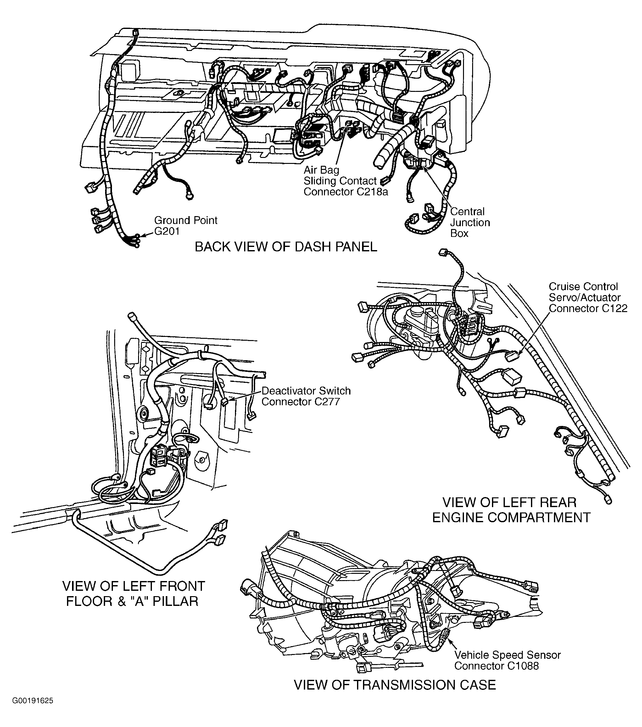
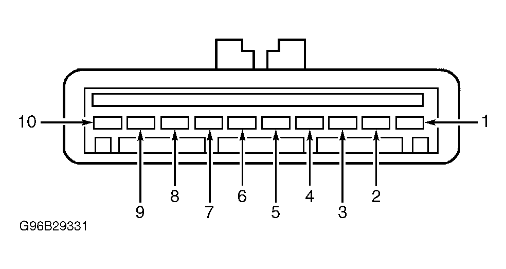
- Disconnect cruise control servo/actuator 10-pin harness connector C122. Cruise control servo/actuator harness connector C122 is located at left rear engine compartment. See Figure. While depressing brake pedal, measure voltage between cruise control servo/actuator harness connector C122 terminals No. 4 (Light Green wire) and No. 10 (Pink/Orange wire). See Figure. See WIRING DIAGRAMS . If voltage is greater than 10 volts, go to next step. If voltage is 10 volts or less, repair open circuit in Light Green wire between brake pedal position switch and cruise control servo/actuator. After repair, test system for normal operation.
- While depressing and releasing brake pedal, measure voltage between cruise control servo/actuator harness connector C122 terminals No. 9 (Orange wire) and No. 10 (Pink/Orange wire). See Figure. See WIRING DIAGRAMS . Voltage should be zero volts with brake pedal firmly depressed, and greater than 10 volts with brake pedal released. If voltage is not as specified, go to next step. If voltage is as specified, replace cruise control servo/actuator. See SERVO/ACTUATOR ASSEMBLY under REMOVAL & INSTALLATION. After repair, test system for normal operation.
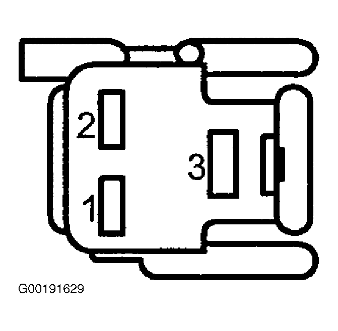
- Disconnect cruise control deactivator switch 3-pin harness connector C277. Cruise control deactivator switch harness connector C277 is located on brake pedal support. See Figure. Connect a fused jumper wire between cruise control deactivator switch harness connector C277 terminals No. 1 and 2. See Figure. Measure voltage between cruise control servo/actuator harness connector C122 terminals No. 9 (Orange wire) and No. 10 (Pink/Orange wire). See Figure. See WIRING DIAGRAMS . If voltage is 10 volts or less, go to next step. If voltage is greater than 10 volts, replace cruise control deactivator switch. See DEACTIVATOR SWITCH under REMOVAL & INSTALLATION. After repair, test system for normal operation.
- Measure resistance between cruise control servo/actuator harness connector C122 terminal No. 9 and cruise control deactivator switch harness connector C277 terminal No. 2 (Orange wire). See Figure and Figure . If resistance is 5 ohms or less, repair open circuit in Light Green/Red wire between cruise control deactivator switch and Central Junction Box (CJB). CJB is located under left side of dash panel. See Figure. See WIRING DIAGRAMS . If resistance is greater than 5 ohms, repair open circuit in Orange wire between cruise control deactivator switch and cruise control servo/actuator. After repair, clear DTC and test system for normal operation.