Disassembly and Assembly
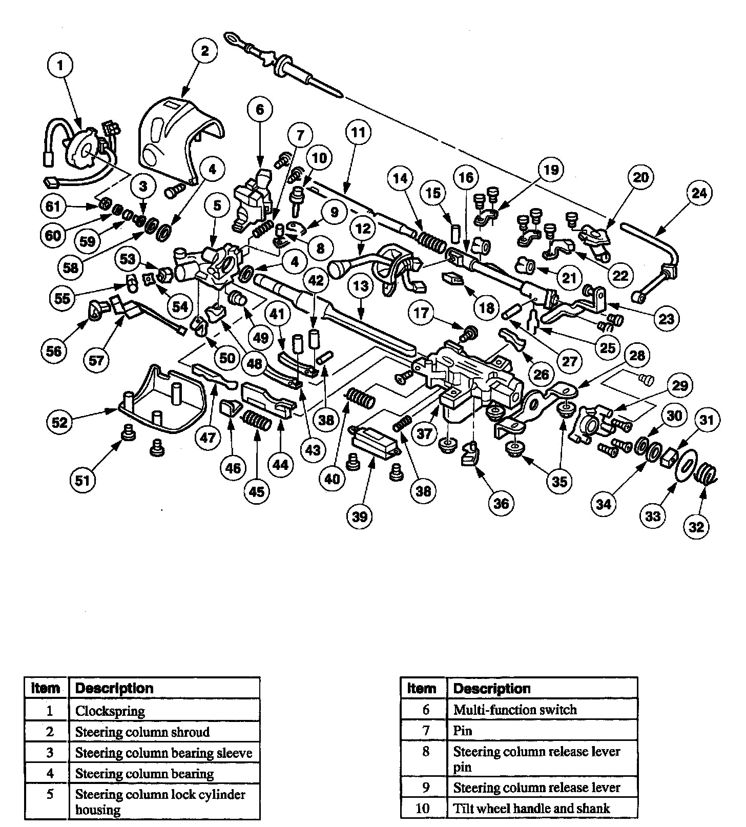
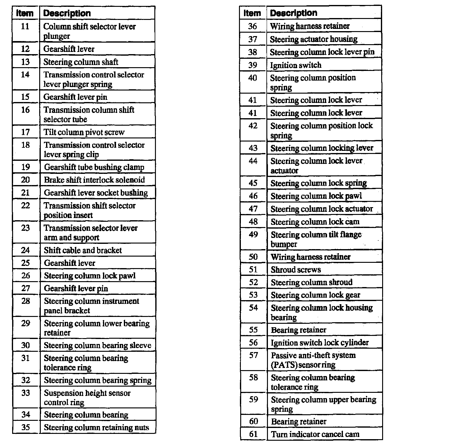
Steering Column
Disassembly
All columns
1. WARNING: To reduce the risk of serious personal injury, read and follow all warnings notes and instructions in the steering column removal and installation procedure.
Remove the steering column.
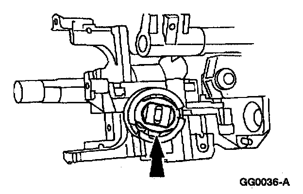
2. CAUTION: Carefully note the position of the steering column lock year, bearing and retainer prior to removal.
Remove the bearing retainer.
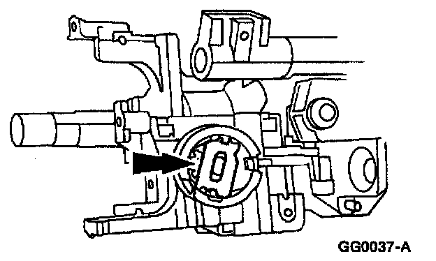
3. Remove the steering column lock housing bearing.
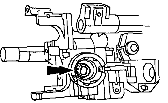
4. Remove the steering column lock gear.
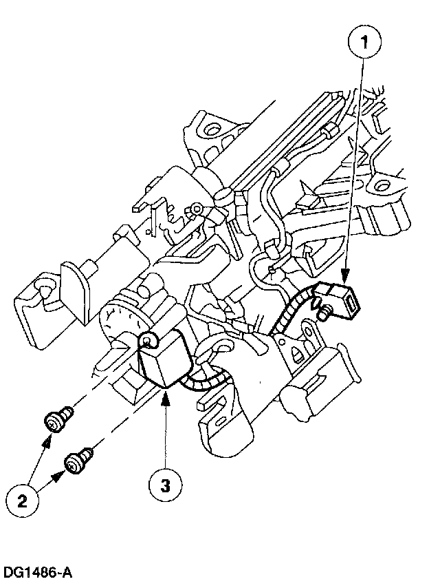
5. Remove the shock absorber electronic steering sensor.
1 Disconnect the electrical connector Tom the steering column.
2 Remove the screws.
3 Remove the shock absorber Tectonic steering sensor.
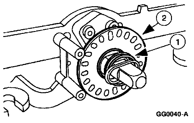
6. Remove the sensor ring.
1 Remove the steering column lower bearing spring.
2 Remove the sensor ring.
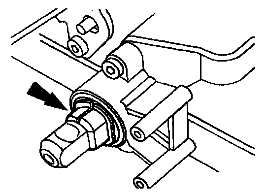
7. Remove the steering column bearing tolerance ring from the steering column shaft.
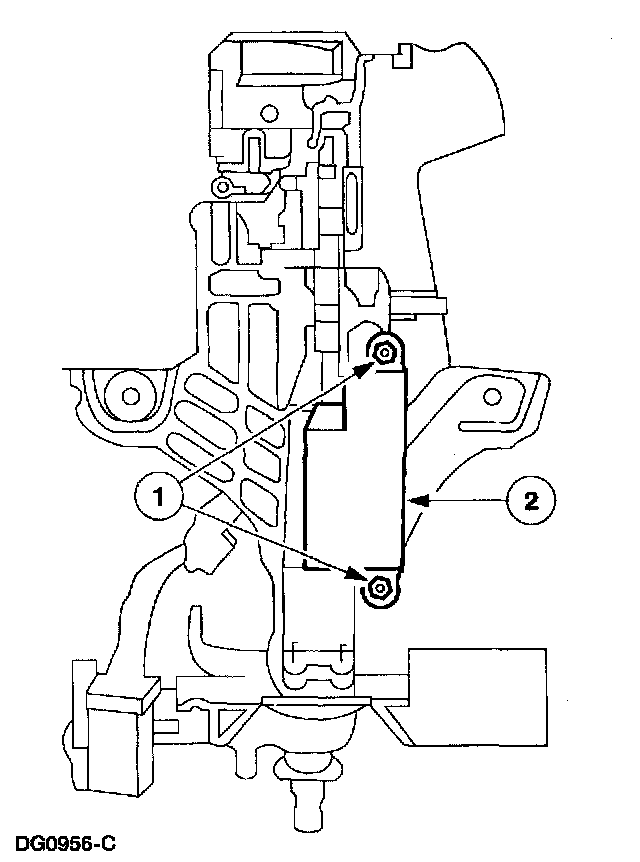
8. Remove the ignition switch.
1 Remove the bolts.
2 Remove the ignition switch.
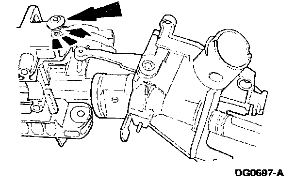
9. Remove the two lock cylinder housing pivot screws.
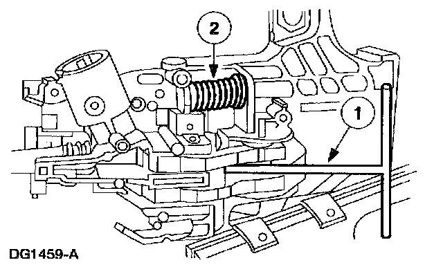
10. WARNING: The steering column position position spring is under compression and may come out with great force.
Remove the steering column lock cylinder housing and the steering column shaft from the steering actuator housing.
1 Ply up on the steering column locking levers using a shop fabricated tool.
2 Remove the steering column position spring.
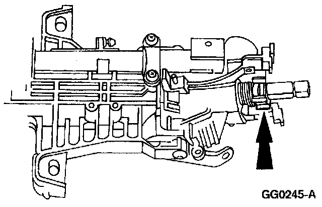
11. Remove the turn indicator cancel cam.
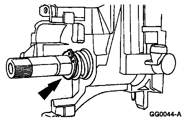
12. Remove the snap ring.
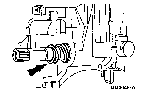
13. Remove the steering column upper bearing spring.
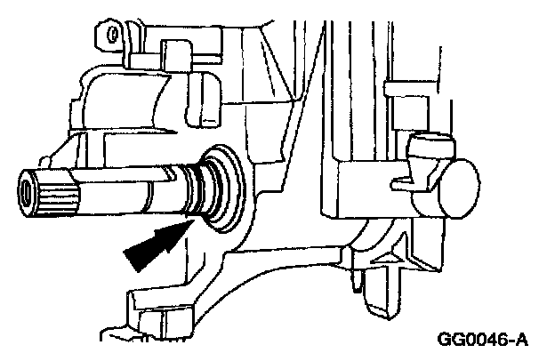
14. Remove the steering column bearing sleeve.
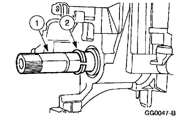
15. Remove the steering column bearing tolerance ring.
1 Slide the steering column shaft in toward the steering column lock cylinder housing, then out.
2 Slide the steering column bearing tolerance ring off the steering column shaft.
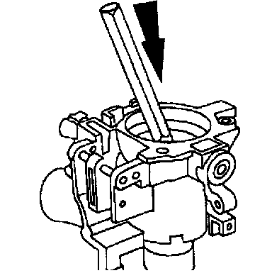
16. Using a suitable punch, remove the steering column bearing Mom the steering column lock cylinder housing.
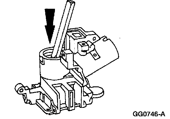
17. Use a suitable punch to remove the steering column bearing from the steering column lock cylinder housing.
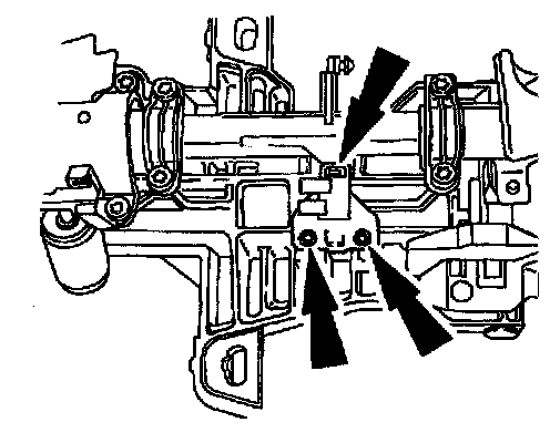
18. Remove the screws and the parking brake release switch.
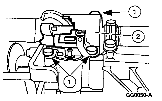
With column shift
19. Remove the brake shift interlock solenoid.
1 Remove the three bolts.
2 Remove the brake shift interlock solenoid.
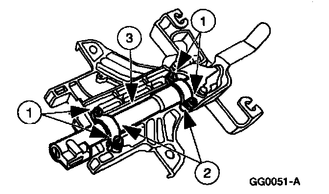
20. Remove the shift tube.
1 Remove the four bolts.
2 Remove the two shift tube clamps.
3 Remove the shift tube.
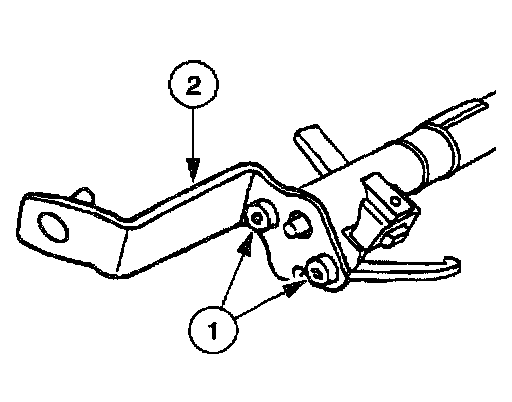
21. Remove the transmission selector lever arm and support.
1 Remove the two bolts.
2 Remove the transmission selector lever arm and support.
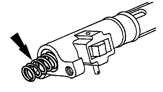
22. Remove the gearshift selector tube spring.
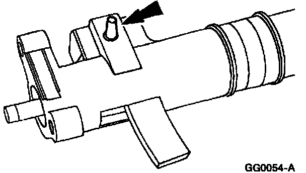
23. Drive out the gearshift lever pin from the shift tube.
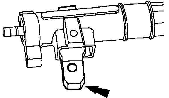
24. Remove the gearshift lever.
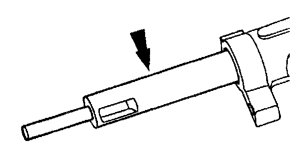
25. Remove the column shift selector lever plunger.
^ If it is bent, install a new column shift selector lever plunger.
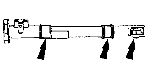
26. Remove the two gearshift lever socket bushings and the transmission control selector lever spring clip.
All columns
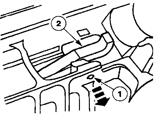
27. Remove the steering column lock pawl.
1 Drive out the steering column lock lever pin.
2 Remove the steering column lock pawl.
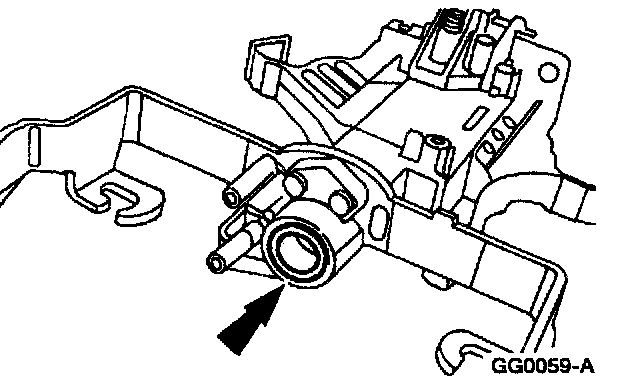
28. Remove the lower steering column bearing and sleeve.
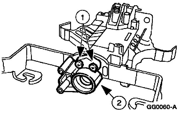
29. Remove the steering column lower bearing retainer.
1 Remove the three bolts.
2 Remove the steering column lower bearing retainer.
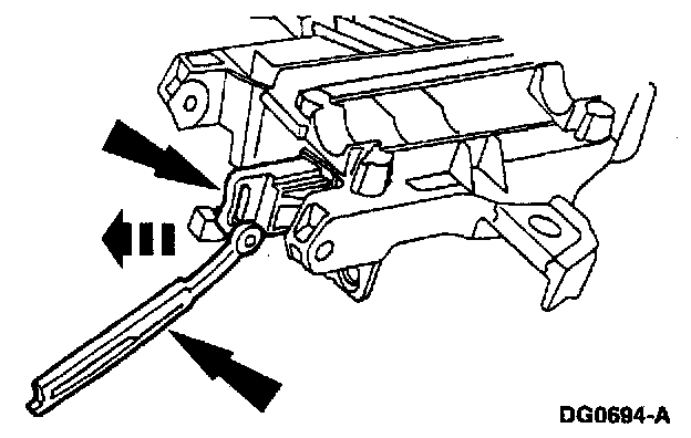
30. Remove the upper steering column lock actuator and the lower steering column lock lever actuator.
Assembly
All columns
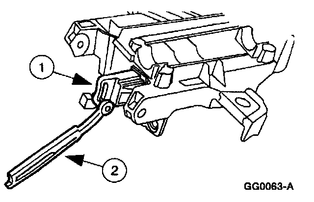
1. Install the steering column lock lever actuator and steering column lock actuator.
1 Use Ignition Lock Grease FOAZ-19584-A or equivalent meeting Ford specification ESA-MlC232-A to lubricate the steering column lock actuator.
2 Install the steering column lock actuator.
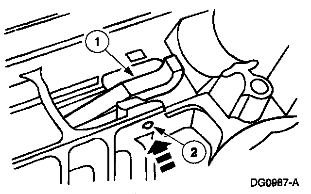
2. NOTE: Coat all surfaces with Ignition Lock Grease FOAZ-19584-A or equivalent meeting Ford specification ESA-M1C282-A.
Install the steering column lock pawl.
1 Position the steering column lock pawl.
2 Drive in the steering column lock lever pin.
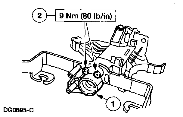
3. Install the steering column lower bearing retainer.
1 Position the steering column lower bearing retainer.
2 Install the three bolts.
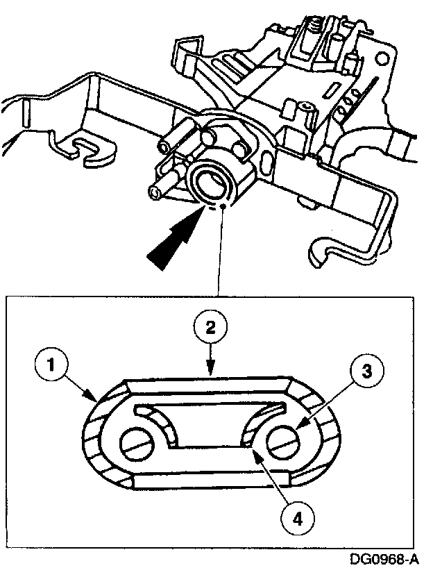
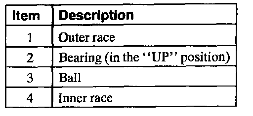
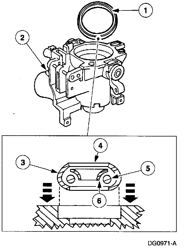
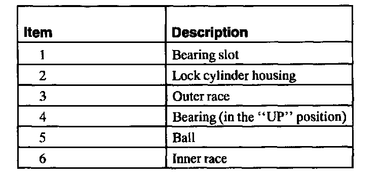
4. NOTE: The "UP" position of the bearing must be facing forward, toward the engine.
Install the steering column bearing and sleeve.
5. Install the steering column bearing and sleeve so that the inner race is visible when installed.
With column shift
6. Install the transmission control selector lever spring clip and the gearshift lever socket bushings on the shift tube.
^ Coat the gearshift lever socket bushings with Steering Gear Grease C3AZ-19578-A or equivalent meeting Ford specification ESW-M1C87-A.
7. Install the column shift selector lever plunger.
^ Coat the column shift selector plunger with Steering Gear Grease C3AZ-19578-A or equivalent meeting Ford specification ESW-M1C87-A.
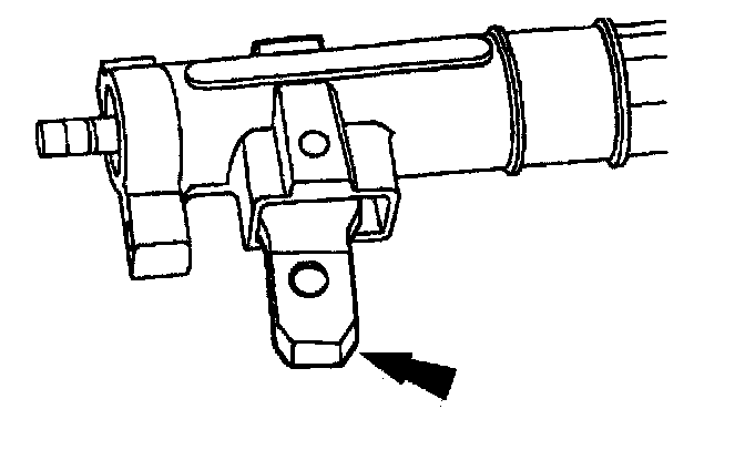
8. Position the gearshift lever in the shift tube.
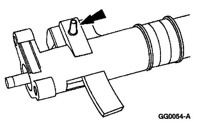
9. CAUTION: Gearshift lever pin must be installed correctly or 1st gear position may be blocked.
Install the gearshift lever pin in the shift tube.
10. Install the gearshift selector tube spring in the shift tube.
^ Coat the end of the spring with Steering Gear Grease C3AZ-19578-A or equivalent meeting Ford specification ESW-M1C87-A.
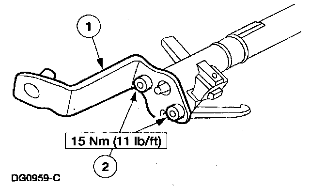
11. Install the transmission selector lever arm and support on the shift tube.
1 Position the transmission selector lever arm and support.
2 Install the bolts.
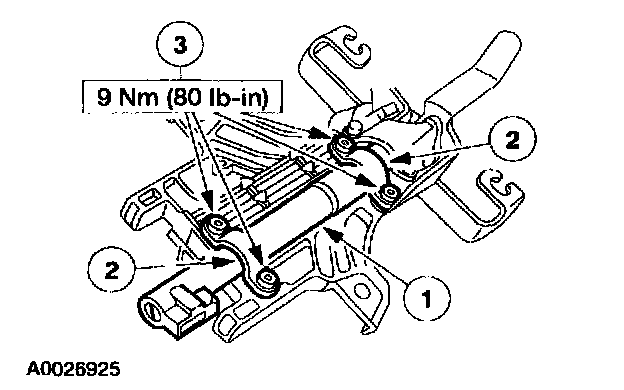
12. Install the shift tube.
1 Position the shift tube.
2 Position the shift tube clamps.
3 Install the bolts.
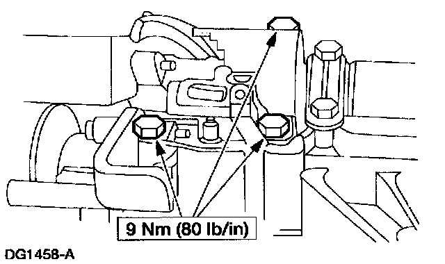
13. Position the brake shift interlock solenoid and install the bolts.
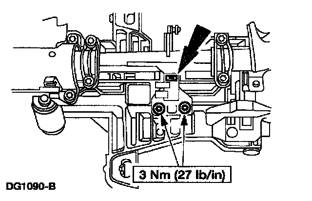
All columns
14. Install the parking brake release switch and screws.
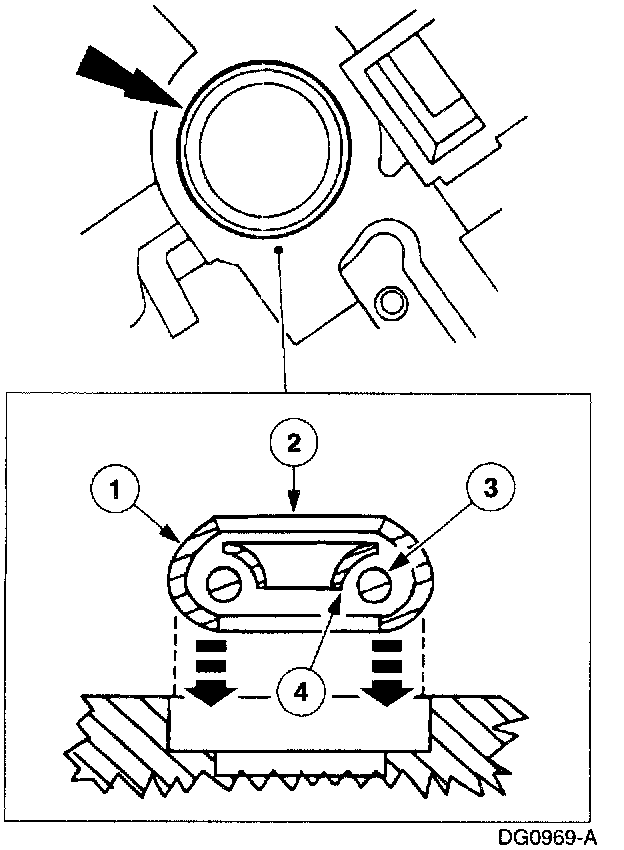
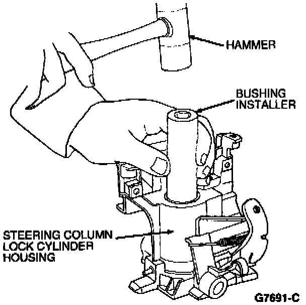
15. CAUTION: Install the upper steering column bearing so that the inner race is visible when installed.
NOTE: Use an appropriate bearing installer or socket.
Install the upper steering column bearing on the steering column lock cylinder housing.
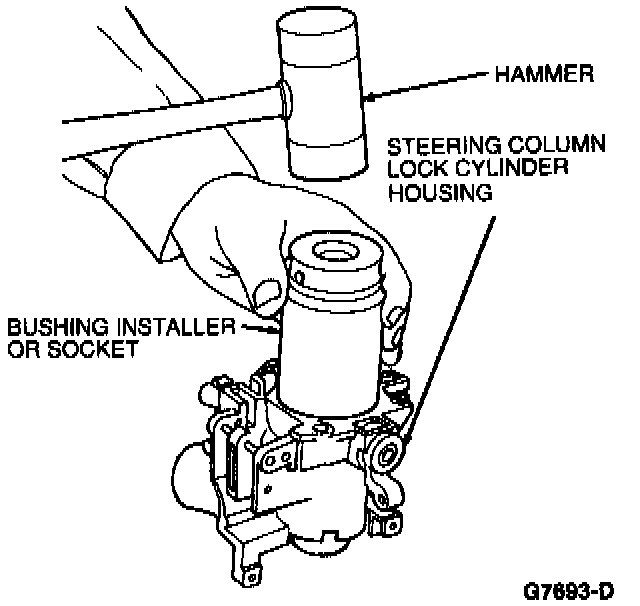
16. CAUTION: Install the lame steering column bearing so that the Ever race is visible when installed.
NOTE: Use an appropriate bearing installer or socket.
On tilt steering columns, install the large steering column bearing into the steering column lock cylinder housing.
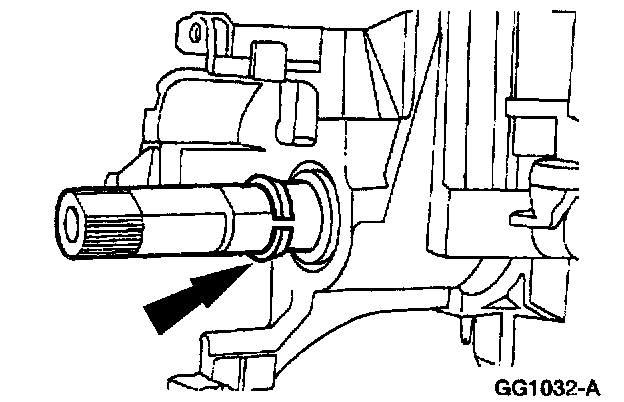
17. Position the steering column shaft in the steering column lock cylinder housing.
^ Install the steering column bearing tolerance ring on the steering column shaft.
18. Install the steering column bearing sleeve.
19. Install the steering column bearing spring.
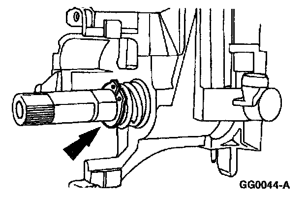
20. Install the snap ring.
21. Install the turn indicator cancel cam.
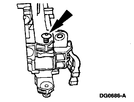
22. Install the lock cylinder housing screws loosely and position the steering actuator housing in a vise.
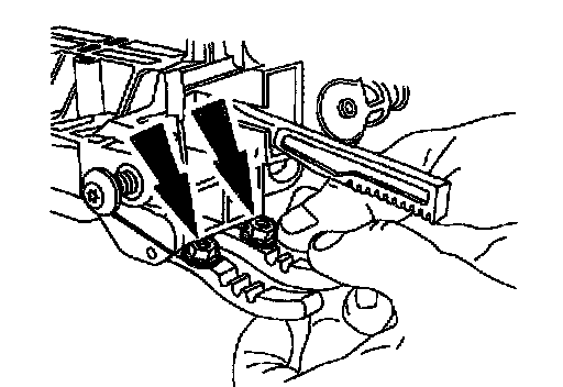
23. Place two nuts or spacers to hold the lock levers away from the actuator housing.
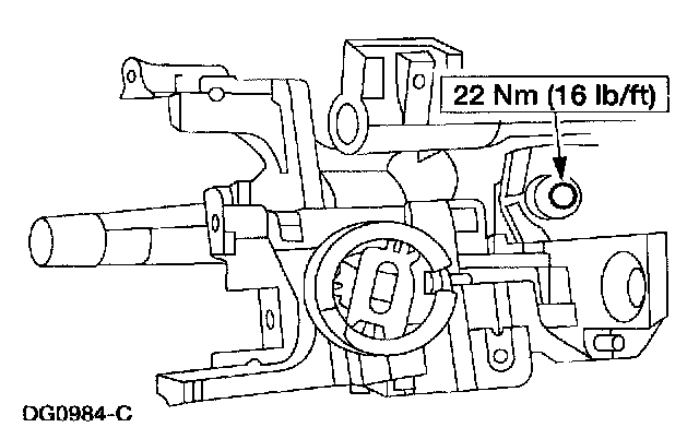
24. NOTE: Lubricate the lock cylinder housing pivot bushings with Rust Penetrant and Inhibitor F2AZ-19A501-A or equivalent meeting Ford specification ESR-M99C56-A.
Install the lock cylinder housing.
^ Position the lock cylinder housing and shaft assembly on the actuator housing.
^ Make sure the upper and lower lock actuators are aligned.
^ Install and compress the steering column position spring.
^ Align the lock cylinder housing bushings with the pivot screws and tighten the screws.
^ Using a long thin screwdriver, remove the nuts installed under the lock levers.
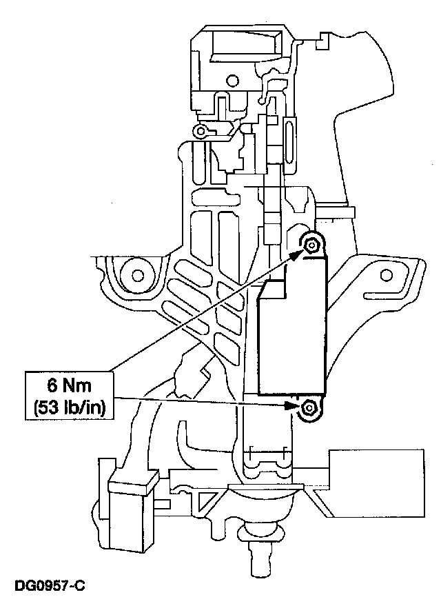
25. Install the ignition switch, aligning the ignition switch with the slot and index mark on the steering column.
^ Install the bolts. Tighten to specification.
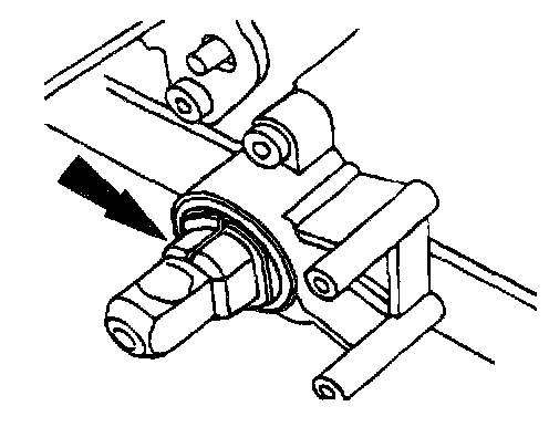
26. Install the steering column bearing tolerance ring.
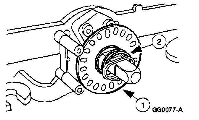
27. Install the sensor ring.
1 Install the sensor ring.
2 Install the steering column bearing spring.
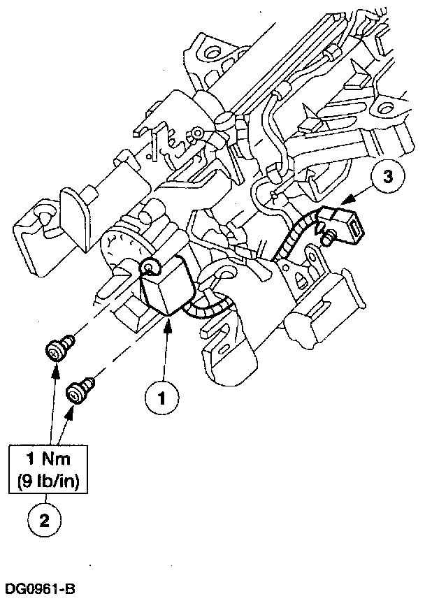
28. Install the shock absorber electronic steering sensor.
1 Position the shock absorber electronic steering sensor.
2 Install the screws.
3 Connect the electrical connector.
29. NOTE: The narrow section of the keyhole in the lock gear should be in the one o'clock position.
Install the steering column lock gear.
^ Use Ignition Lock Grease FOAZ-19584-A or equivalent meeting Ford specification ESA-M1C232-A to coat the steering column lock gear.
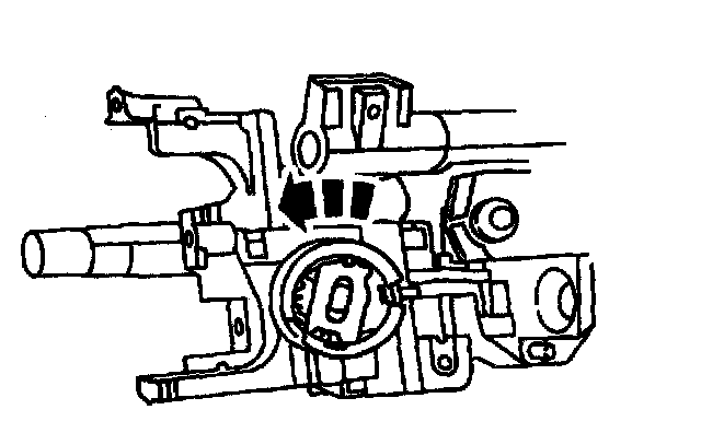
30. Install the steering column lock housing bearing.
^ The narrow section of the keyhole should be in the one o'clock position, with the tab inboard at the three o'clock position, and rotate it counterclockwise.
^ Lubricate the steering column lock housing bearing with Ignition Lock Grease FOAZ-19584-A or equivalent meeting Ford specification ESA-M1C232-A.
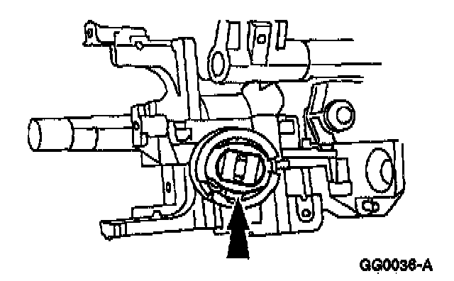
31. Install the steering column upper bearing retainer firmly to engage the four retention tabs into the lock housing.
32. WARNING: To reduce the risk of serious personal injury, read and follow all warnings notes and instructions in the steering column removal and installation procedure.
Install the steering column.