Rear Upper
Arm-UpperRear Suspension:
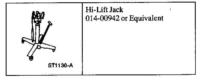
Special Tool(s)
Removal
CAUTION: Suspension are critical parts became the, attest the performance of vital components and their failure can result in major service expense. They must be replaced with the same part number or an equivalent part if replacement is necessary. Do not use a replacement part of lesser quality or substitute design. Torque value must be Red as specified during reassembly to endure proper retention of these ports.
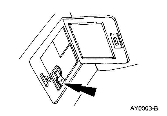
Vehicles equipped with air suspension
1. WARNING: The electrical power to the air suspension system must be turned off prior to hoisting, jacking or towing an air suspension vehicle. Failure to do so can result in unexpected inflation or deflation of the air springs, which can result in shifting of the vehicle during these operations.
Turn the air suspension service switch off.
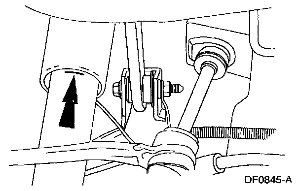
All vehicles
2. Mark the rear suspension shock absorber Restive to the protective sleeve with the vehicle in a static, level ground position (curb height).
3. Raise and support the vehicle.
4. Use the special tool 01-00942 or equivalent to support the rear axle.
Vehicles equipped with air suspension
5. WARNING: Do not remove an air spring under any circumstances when there is air pressure in the air spring. Do not remove any components supporting an air spring without exhausting the air.
Release the air pressure from the air springs.
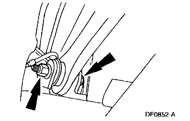
All vehicles
6. CAUTION: Do not use excessive force when removing the pivot bolt and flag nut on the right upper suspension arm to axle bracket. Damage to the brake line can occur.
Remove and discard the rear suspension upper arm pivot bolt and nut from the axle bracket.
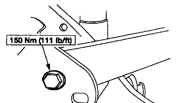
7. Remove and discard the rear suspension upper arm pivot bolt and nut from the fume bucket. Remove the rear suspension upper arm.
Installation
All vehicles
1. NOTE: The rear suspension upper arm bolts must be tightened with the vehicle at curb height.
NOTE: The rear suspension upper arms are interchangeable from side-to-side with "FRONT" and "OUTBOARD" stamped on the side of the arms for positioning during installation.
Position the rear suspension upper arm to the frame bracket and install a new pivot bolt and nut. Insert the bolt so the nut faces inboard. Do not tighten at this time.
2. Position the rear suspension upper arm to the axle bracket and install a new pivot bolt and nut. Insert the bolt so the nut faces outboard. Do not tighten at this time.
3. Raise the axle assembly to the position that compresses the shock absorber to the previously established alignment mark (curb height).
4. Tighten the bolt.
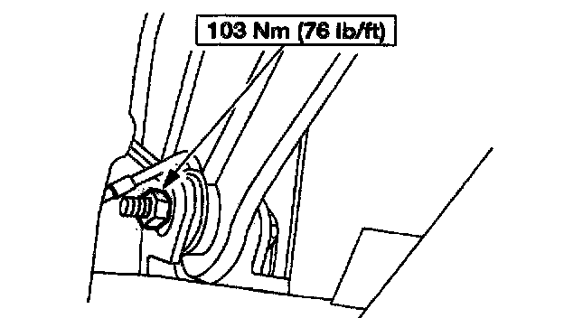
5. Tighten the bolt.
6. Remove the special tool 014-00942 or equivalent.
7. Lower the vehicle.
Vehicles equipped with air suspension
8. Turn the air suspension service switch on.
9. Inflate the air springs.