Steps 51 - End
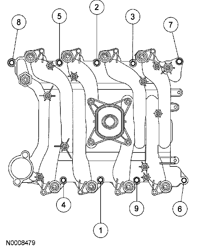
51. Install the intake manifold and tighten the bolts in the sequence shown to 26 Nm (18 ft. lbs.).
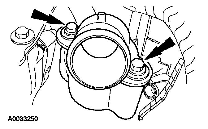
52. NOTE: Lubricate the O-ring seal with clean engine coolant.
Install the thermostat housing and the bolts.
^ Tighten to 28 Nm (18 ft. lbs.).
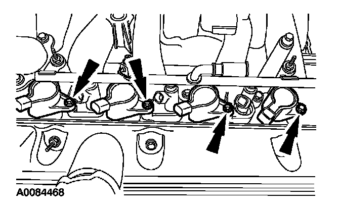
53. NOTE: Apply dielectric compound to the inside of the coil boots.
Install all 8 ignition coils and the bolts.
^ Tighten to 6 Nm (53 inch lbs.).
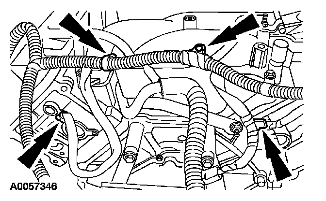
54. Position the fuel charging wiring harness on the top of the engine.
^ Connect the harness locators to the engine.
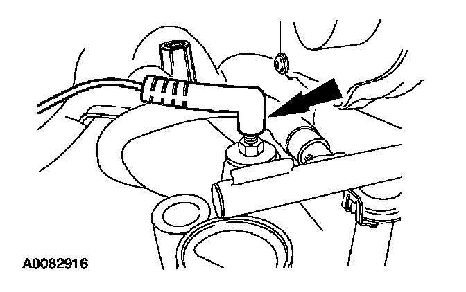
55. Connect the ground wire.
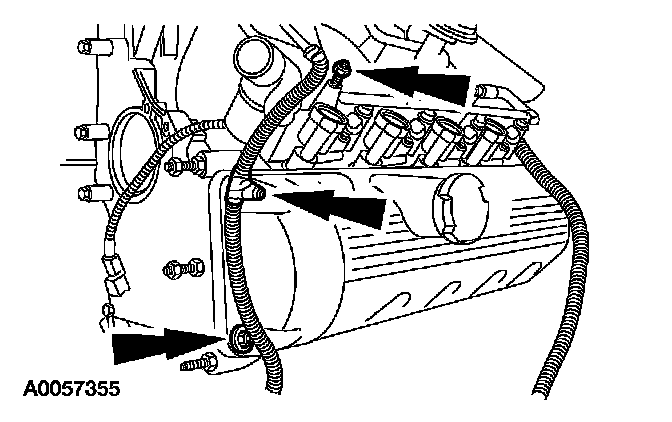
56. Position the starter wiring harness and connect the wiring harness retainers.
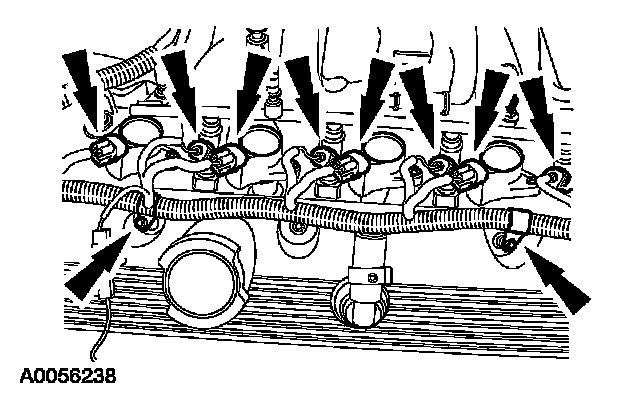
57. Connect the LH fuel injector and the coil on plug electrical connectors. Install the wiring harness retainers.
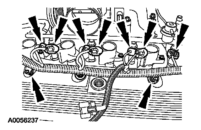
58. Connect the RH fuel injector, coil on plug and ground electrical connectors. Install the wiring harness retainers.
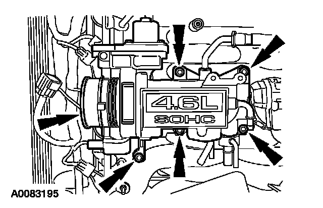
59. Install the throttle body adapter and bolts.
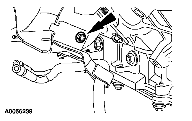
60. Install the bolt.
^ Tighten to 10 Nm (89 inch lbs.)
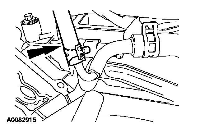
61. Connect the coolant hose.
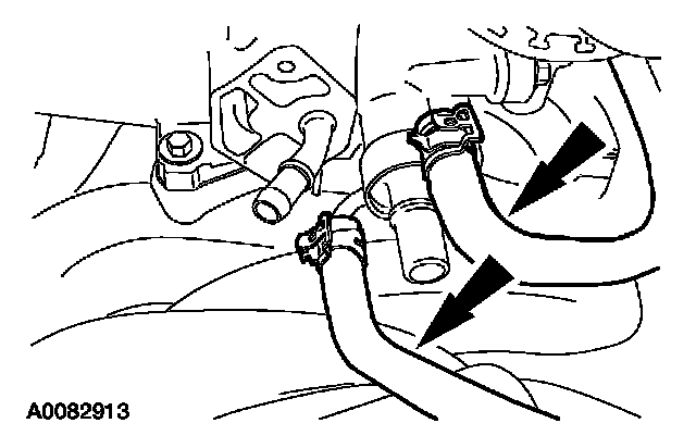
62. Connect the coolant hoses.
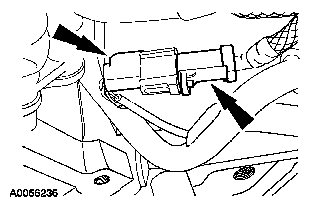
63. Connect the Knock Sensor (KS) electrical connector and install the harness retainer to the intake manifold.
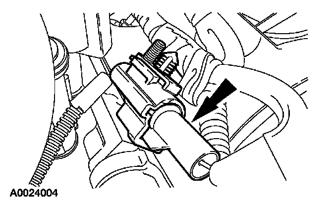
64. Connect the Cylinder Head Temperature (CHT) sensor electrical connector.
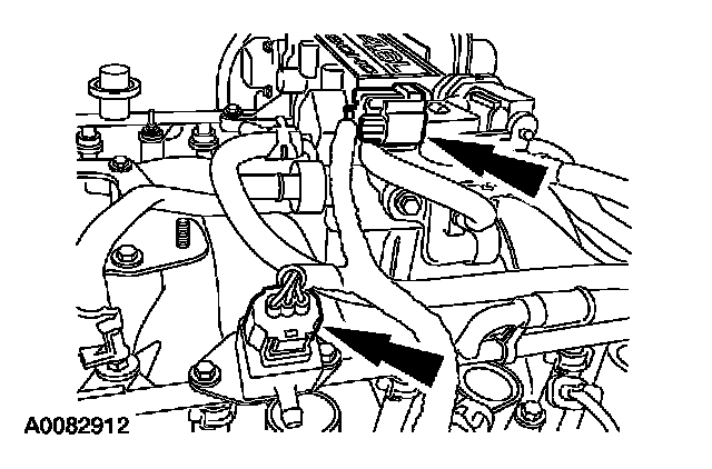
65. Connect the EGR system module and fuel pressure sensor electrical connectors.
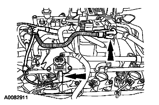
66. Position the vacuum harness on the engine and connect the EGR system module and fuel pressure sensor vacuum fittings.
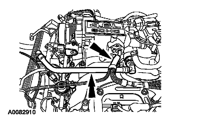
67. Install the Positive Crankcase Ventilation (PCV) tube and connect the vacuum tube to the throttle body adapter.
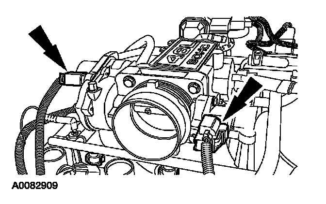
68. Connect the Throttle Position (TP) sensor and the electronic throttle body electrical connectors.
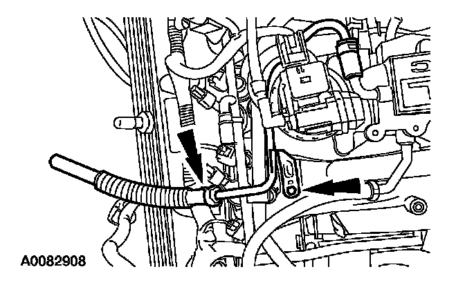
69. Install the brake booster vacuum hose and bolt.
^ Tighten to 10 Nm (89 inch lbs.).
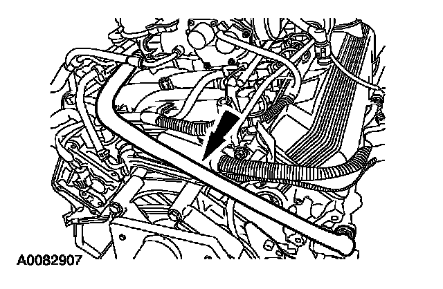
70. Install the Exhaust Gas Recirculation (EGR) tube to the exhaust manifold and the EGR system module.
^ Tighten to 40 Nm (30 ft. lbs.).
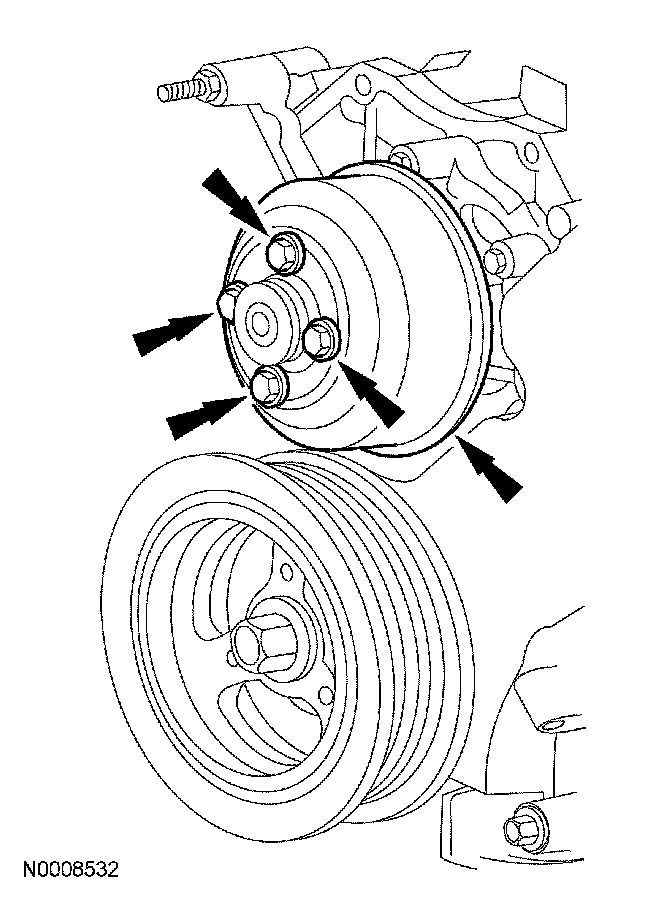
71. Position the coolant pump pulley on the coolant pump and install the bolts.
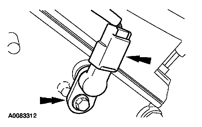
72. Connect the Camshaft Position (CMP) sensor electrical connector.
^ Tighten to 10 Nm (89 inch lbs.).
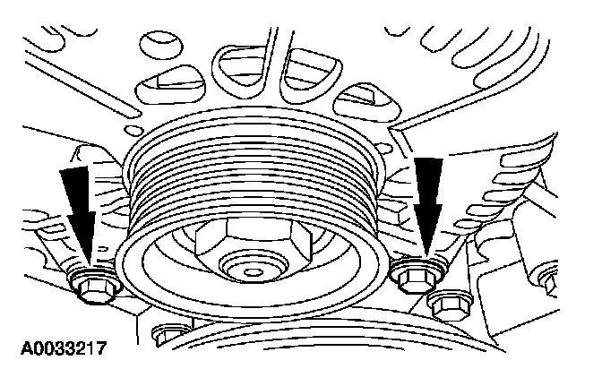
73. Install the generator and the bolts.
^ Tighten to 25 Nm (18 ft. lbs.).
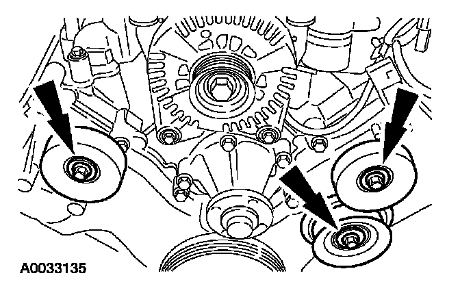
74. Install the idler pulleys and the bolts.
^ Tighten to 25 Nm (18 ft. lbs.).
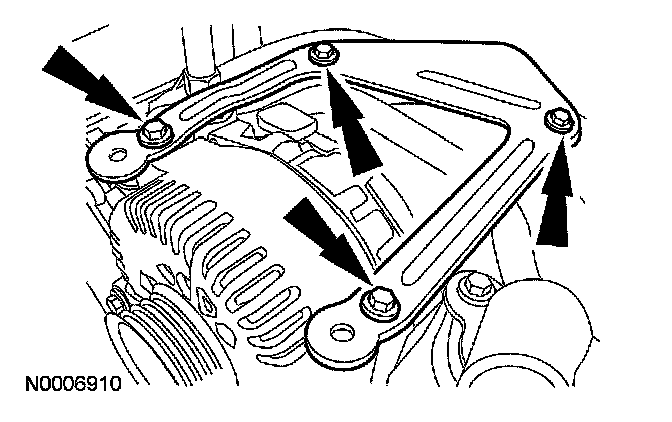
75. Install the generator bracket and the bolts.
^ Tighten to 10 Nm (89 inch lbs.).
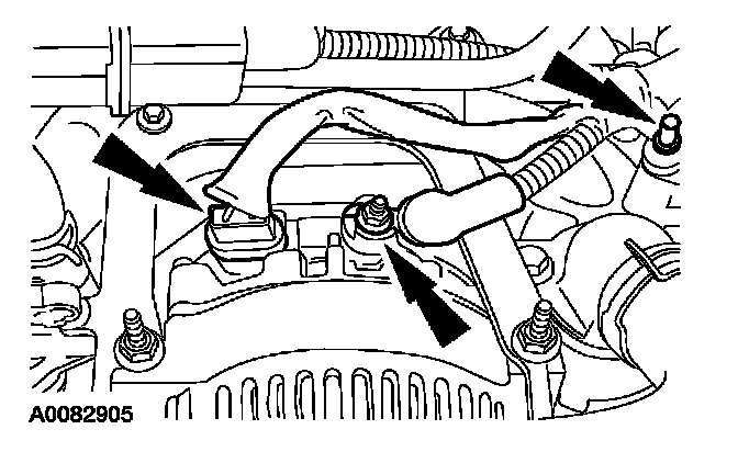
76. Connect the generator electrical connections.
^ Tighten to 8 Nm (71 inch lbs.).
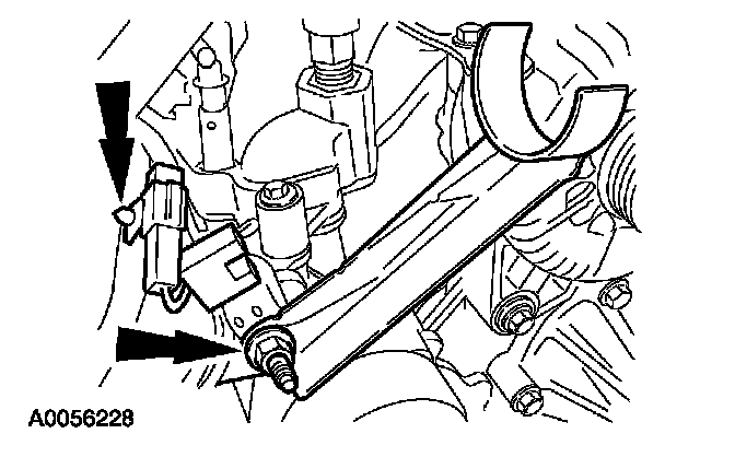
77. Install the upper radiator hose bracket and the radio interference capacitor.
^ Tighten to 10 Nm (89 inch lbs.).
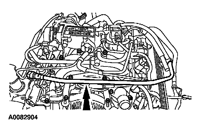
78. Install the crankcase air inlet tube.
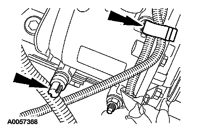
79. Position the wiring harness and connect the retainers.
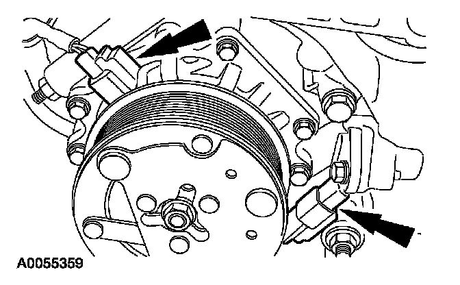
80. Connect the A/C compressor and the Crankshaft Position (CKP) sensor electrical connector.
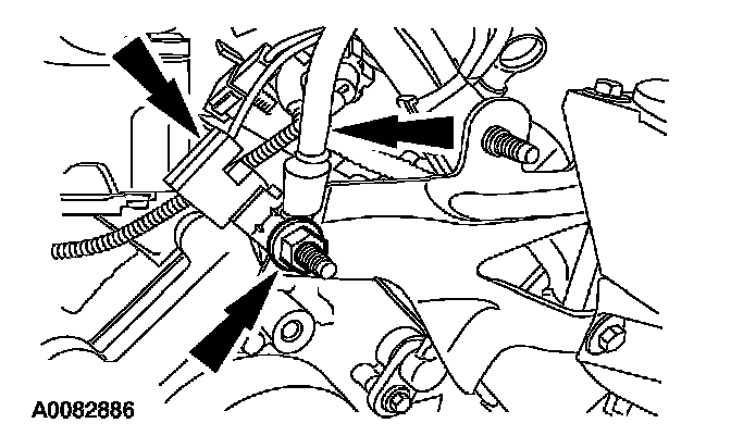
81. Install the power steering reservoir bracket, radio interference capacitor, ground cable and nut.
^ Tighten to 25 Nm (89 inch lbs.).
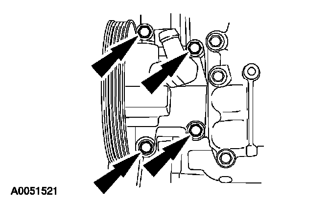
82. Install the power steering pump and the bolts.
^ Tighten to 20 Nm (15 ft. lbs.).
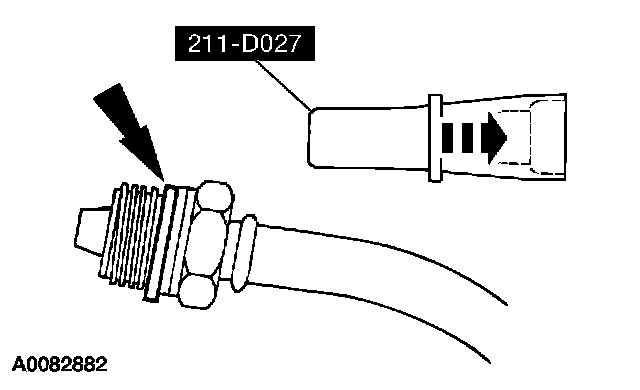
83. Using the special tool, install a new seal on the power steering pressure hose fitting.
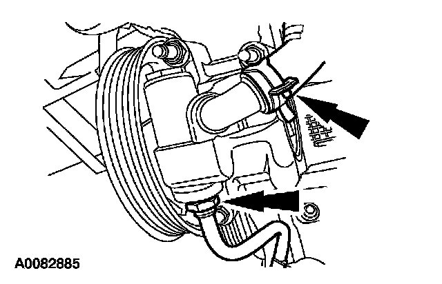
84. Connect the return and pressure hoses to the power steering pump.
^ Tighten to 65 Nm (48 ft. lbs.).
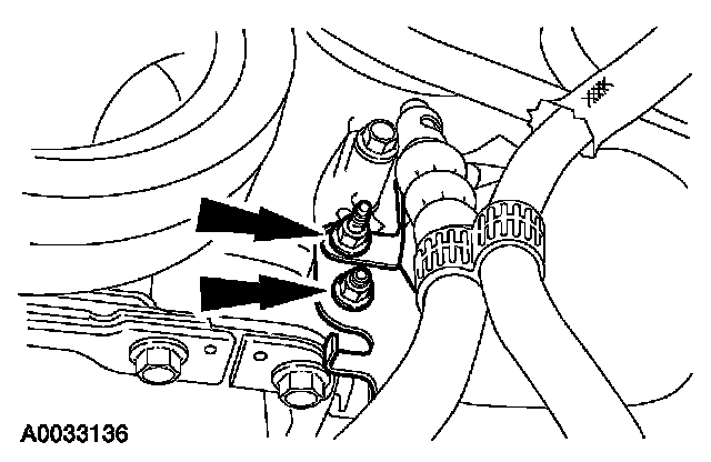
85. Install the power steering hose support bracket and the nuts.
^ Tighten to 11 Nm (8 ft. lbs.).
86. Connect the oil pressure sensor electrical connector.
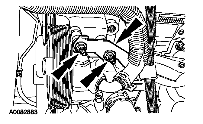
87. Install the wiring harness bracket and nuts.
^ Tighten to 20 Nm (15 ft. lbs.).
88. Install the accessory drive belt.
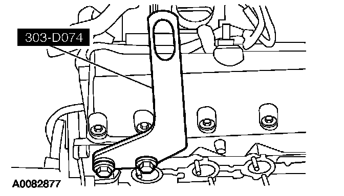
89. NOTE: RH is shown, LH is similar.
Install the engine lift brackets.
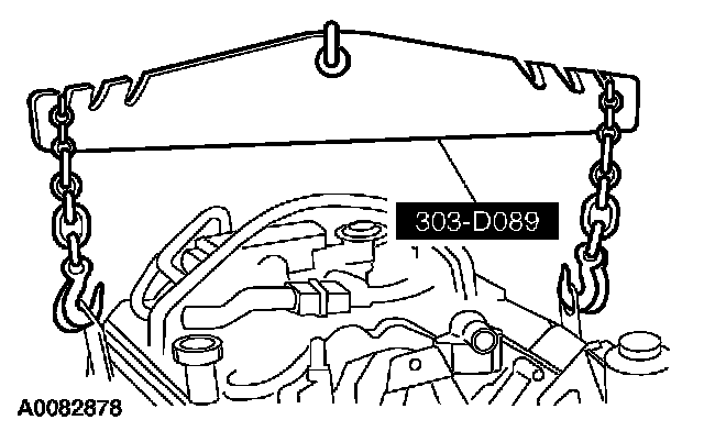
90. Attach the special tool to a floor crane and the engine and remove the engine from the engine stand.
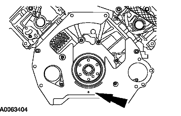
91. Install the rear engine cover.
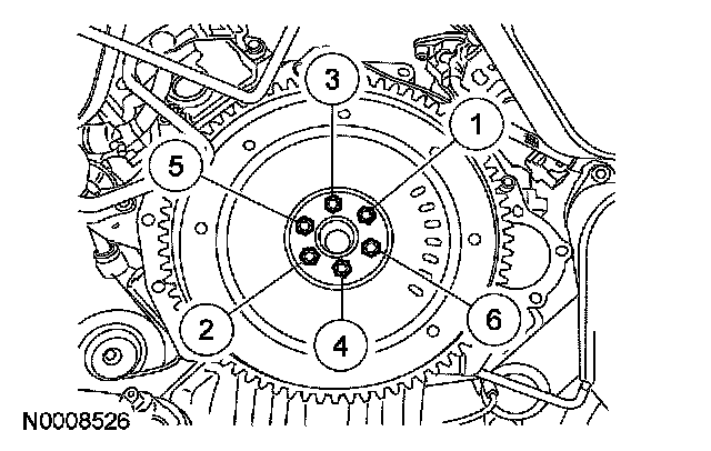
92. Position the flexplate and install the bolts finger tight.
^ Tighten the bolts in the sequence shown to 80 Nm (59 ft. lbs.).
93. Install the engine.