Steering Gear: Service and Repair
Steering Gear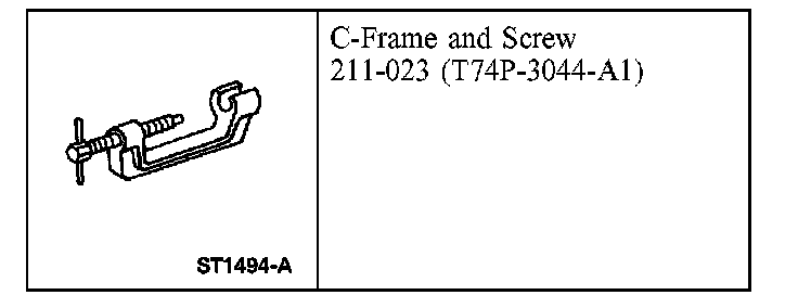
Special Tool(s)
Part 1:
Part 2:
Removal and Installation
All vehicles
CAUTION: While repairing the power steering system, care should be taken to prevent the entry of contaminants or premature failure of the power steering components can result.
1. With the vehicle in NEUTRAL, position it on a hoist.
2. CAUTION: Do not allow the steering wheel to rotate while the lower shaft is disconnected or damage to the clockspring can result. If there is evidence that the lower shaft has rotated, the clockspring must be removed and recentered.
Hold the steering wheel in the straight-ahead position using a suitable device.
3. Using a suitable suction device, drain the power steering fluid reservoir.
4. Remove the 2 bolts and the oil drip shield.
^ To install, tighten to 15 Nm (11 ft. lbs.).
5. NOTE: Install a new lower shaft-to-steering gear bolt.
Remove and discard the lower shaft-to-steering gear bolt.
^ To install, tighten to 48 Nm (35 ft. lbs.).
6. Disconnect the lower shaft from the steering gear.
7. Remove the steering line clamp plate nut.
^ To install, tighten to 25 Nm (18 ft. lbs.).
8. Rotate the steering line clamp plate and disconnect the power steering lines.
9. NOTE: New O-rings must be installed whenever the power steering lines are disconnected.
Remove and discard the 2 O-rings.
10. NOTE: New cotter pins must be installed.
Remove and discard the 2 cotter pins.
11. NOTE: New tie-rod end nuts must be installed.
Remove and discard the 2 tie-rod end nuts.
^ To install, tighten to 70 Nm (52 ft. lbs.).
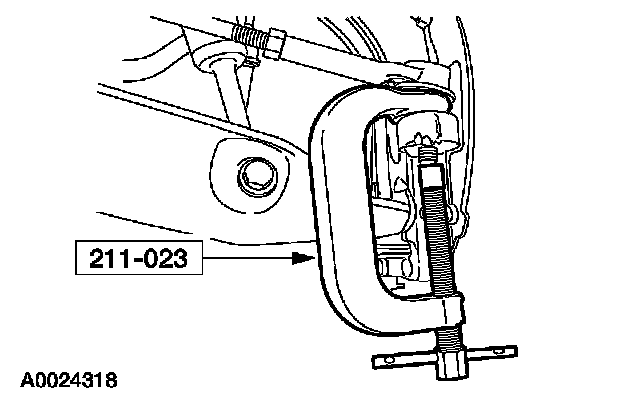
12. CAUTION: Do not damage the tie-rod end boot when installing the special tool.
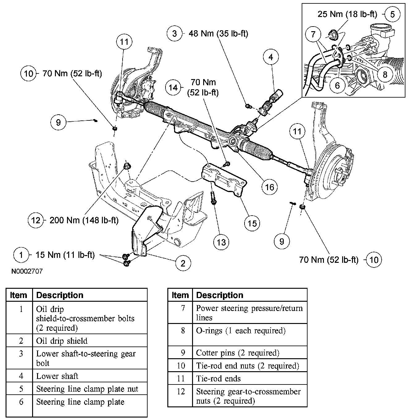
Using the special tool, separate the 2 tie-rod ends from the wheel knuckle.
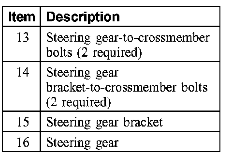
13. Remove the 2 steering gear-to-crossmember nuts and bolts.
^ To install, tighten to 200 Nm (148 ft. lbs.).
14. Remove the 2 bolts and remove the steering gear bracket.
^ To install, tighten to 70 Nm (52 ft. lbs.).
4WD vehicles
NOTE: On 4WD vehicles, the following steps (LH lower arm only) must be carried out to provide clearance to remove the steering gear.
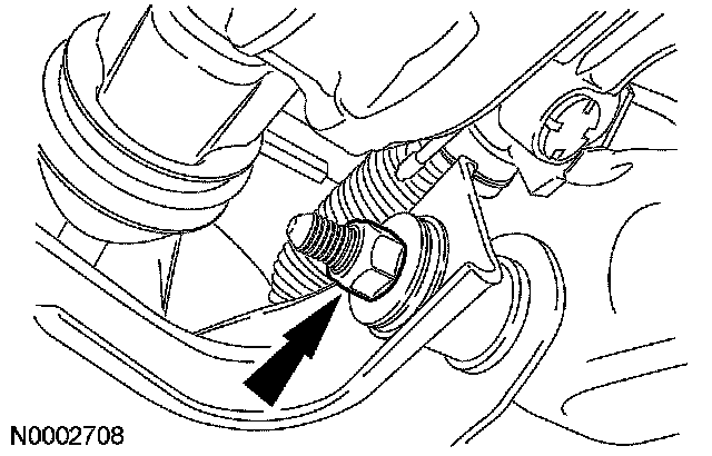
15. CAUTION: Do not tighten the LH lower arm inboard mounting nuts until the installation procedure is complete and the weight of the vehicle is resting on the wheel and tire assemblies. Make sure to tighten the lower arm forward nut before tightening the lower arm-to-frame nuts.
NOTE: It is not necessary to disconnect the LH lower ball joint.
Remove the lower arm forward nut and flag bolt.
^ Discard the nut.
^ To install, tighten to 400 Nm (295 ft. lbs.).
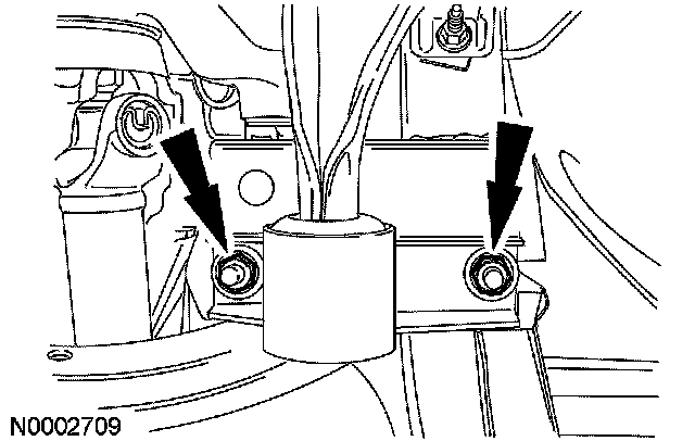
16. Remove and discard the 2 lower arm-to-frame nuts.
^ To install, tighten to 150 Nm (111 ft. lbs.).
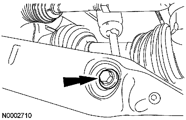
17. Remove the shock absorber-to-lower arm bolt and flag nut.
^ Discard the flag nut.
^ To install, tighten to 350 Nm (258 ft. lbs.).
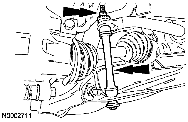
18. Remove the stabilizer bar connecting link nut and disconnect the link.
^ To install tighten to 25 Nm (18 ft. lbs.).
All vehicles
19. Remove the steering gear from the LH side of the vehicle.
20. To install, reverse the removal procedure.
^ Install 2 new O-rings.
^ Fill the power steering system.