Brake Pedal and Bracket
Brake Pedal and Bracket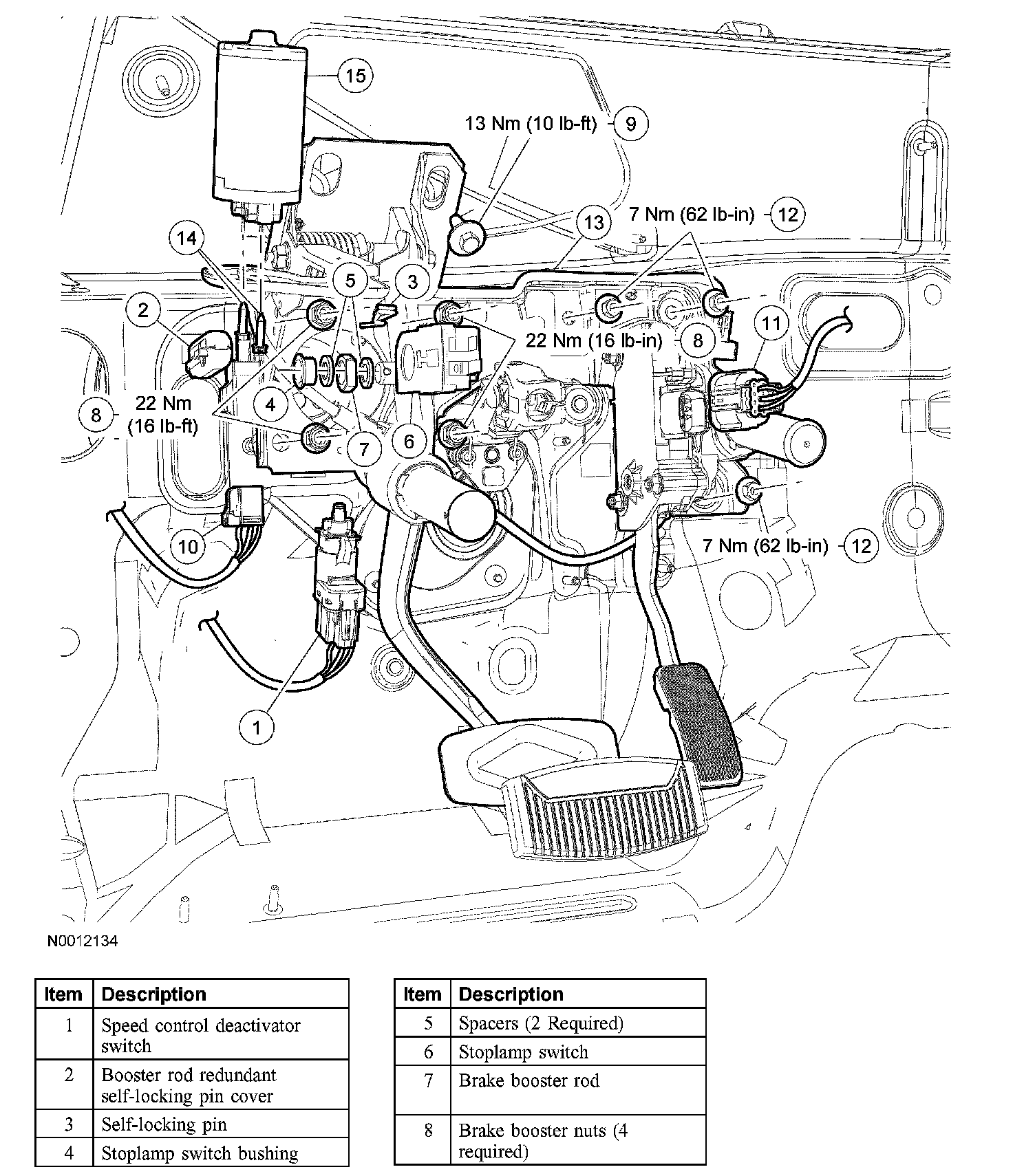
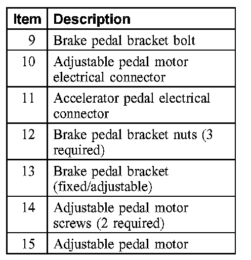
NOTE: Adjustable pedals are shown the fixed pedals are similar.
Removal
1. NOTE: If equipped with adjustable pedals, when removing the adjustable pedal assembly, make sure the pedals are adjusted to the full forward position.
Depower the Supplemental Restraint System (SRS).
2. CAUTION: The brake pedal must be connected to the booster rod, in an at rest position, before removing the speed control deactivator switch or the switch will be damaged.
If equipped, remove the speed control deactivator switch.
3. Disconnect the booster rod redundant self locking pin cover and the self locking pin.
4. Remove the stoplamp switch bushing, spacers and the brake booster rod from the brake pedal and position the stoplamp switch aside.
5. If equipped with power adjustable pedals, disconnect the adjustable pedal motor electrical connector.
6. If equipped with adjustable pedals, disconnect the accelerator pedal motor electrical connector.
7. Remove and discard the 4 brake booster nuts.
8. Position the brake master cylinder and brake booster assembly forward to allow the brake pedal assembly to clear the studs.
9. Remove the 3 brake pedal bracket nuts.
10. Remove the 2 wiper arms.
11. Remove the cowl grille.
^ The grille is secured with 14 spring clips. Pull upward on the grille to release the clips.
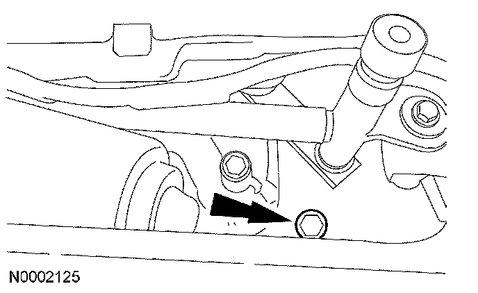
12. Remove the 2 instrument panel support bracket bolts and the 2 nuts.
13. Remove the front floor console.
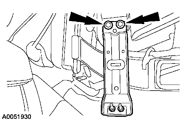
14. Remove the 4 instrument panel support bracket bolts from the LH and RH instrument support brackets.
15. Remove the 2 door scuff plates.
16. Remove the retainer and the 2 A pillar lower trim panels.
17. Remove the 2 instrument panel side finish panels.
18. Remove the 4 A pillar passenger assist handles caps.
19. Remove the 4 bolts and the 2 A pillar passenger assist handles.
20. Remove the 2 windshield side garnish mouldings.
21. Remove the defroster grille.
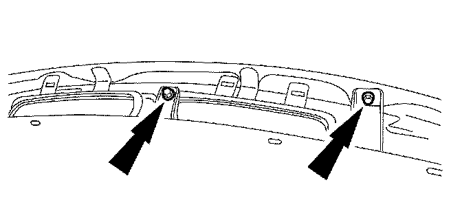
22. Remove the duct bolt and the top instrument panel to cower bolt.
23. Remove the 2 steering column opening cover screws and the steering column opening cover panel.
24. CAUTION: Do not allow the steering wheel to rotate while the steering column intermediate shaft is disconnected or damage to the clockspring can result. If there is evidence the steering column shaft has rotated, the clockspring must be removed and centered.
Secure the steering wheel to prevent it from rotating.
25. Remove the steering intermediate shaft pinch bolt and separate the steering shafts.
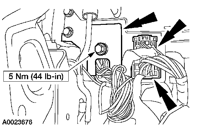
26. Loosen the bolt and disconnect the bulkhead electrical connectors.
27. Remove the 4 instrument panel to cowl support bolts.
28. Position the instrument panel approximately 25.4 mm (1 inch) away from the dash panel.
29. Remove the brake pedal assembly from the vehicle.
Installation
1. Position the brake pedal assembly in the vehicle.
2. Position the instrument panel and install the 4 instrument panel to cowl support bolts.
^ Tighten to 25 Nm (18 ft. lbs.).
3. Connect the steering shafts and install the pinch bolt.
^ Tighten to 30 Nm (22 ft. lbs.).
4. Connect the bulkhead electrical connectors and tighten the bolt.
5. Position the steering column opening cover and install the 2 screws.
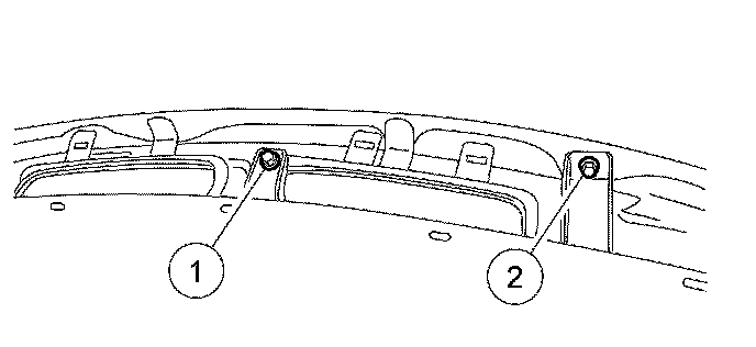
6. Install the instrument panel duct support bolt and the instrument panel to cowl support bolt.
1 Tighten to 9 Nm (80 inch lbs.).
2 Tighten to 30 Nm (22 ft. lbs.).
7. Install the defroster grille.
8. Install the 2 windshield side garnish mouldings.
9. Position the 2 A pillar passenger assist handles and install the 4 bolts.
^ Tighten to 11 Nm (8 ft. lbs.).
10. Install the 4 A pillar passenger assist handles caps.
11. Install the 2 instrument panel side finish panels.
12. Install the 2 A pillar lower trim panels and the retainers.
13. Install the 2 door scuff plates.
14. Install the 4 instrument panel support bracket bolts in the LH and RH instrument support brackets.
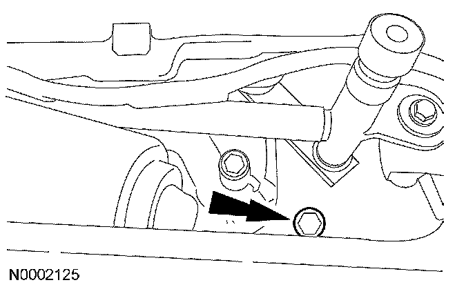
15. Install the instrument panel support bolt.
^ Tighten to 30 Nm (22 ft. lbs.).
16. Install the cowl grille.
17. Install the 2 wiper arms.
18. Install the front floor console.
19. Install the 3 brake pedal bracket nuts.
^ Tighten to 7 Nm (62 inch lbs.).
20. Position the brake master cylinder and brake booster assembly into the brake pedal bracket assembly.
21. Install the 4 new brake booster nuts.
^ Tighten to 22 Nm (16 ft. lbs.).
22. If equipped with power adjustable pedals, connect the adjustable pedal motor electrical connector.
23. If equipped with adjustable pedals, connect the accelerator pedal electrical connector.
24. Connect the brake booster rod and position the stoplamp switch, bushing, and spacers on the brake pedal.
25. Install the redundant self locking pin and cover.
26. CAUTION: The brake pedal must be connected to the brake booster rod, in an at rest position, before installing the speed control deactivator switch or the switch will be damaged.
If equipped, install the speed control deactivator switch.
27. Repower the Supplemental Restraint System (SRS).