Adjustment Procedure
The suspension can be adjusted for front camber and front toe. However, each of these adjustments are related to each other. For example, when you adjust camber, the toe will change. Therefore, you must adjust the front wheel alignment whenever you adjust camber or toe.
NOTE: After adjusting the wheel alignment, do the VSA sensor neutral position memorization and steering angle sensor neutral position clear.
- 1. Vehicle - Lift
- 2. Front Camber - Adjust
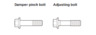
The front camber can be adjusted by exchanging one or both of the damper pinch bolts with a smaller diameter adjusting bolt. The difference between the adjusting bolt diameter and the pinch bolt hole diameter allows for a small range of adjustment.
NOTE: Refer to the Parts Catalog if you need to use an adjusting bolt.
1. Remove the front wheels .
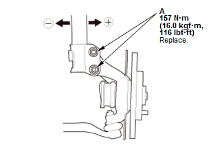
2. Loosen the damper pinch bolts (A), and adjust the camber angle by moving the bottom of the damper within the range of the damper pinch bolt free play.
3. Tighten the damper pinch bolts to the specified torque.
4. Clean the mating surfaces between the brake disc and the inside of the wheel, then install the front wheels .
5. Lower the vehicle to the ground, and bounce the front of the vehicle up and down several times to stabilize the suspension.
6. Measure the camber angle.- If the measurement is within specification, measure the toe-in.
- If the measurement is not within specification, go to step 7.
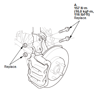
7. Remove the front wheels . 8. Replace the damper pinch bolts with the adjusting bolts (A), and adjust the camber angle.
NOTE:- The camber angle can be adjusted up to ±20 ' (center of tolerance) by replacing one damper pinch bolt with the adjusting bolt.
- The camber angle can be adjusted up to ±40 ' by replacing both damper pinch bolts with the adjusting bolts.
- During installation, install the damper pinch bolts to the same direction as removal.
9. Tighten the damper pinch bolts to the specified torque.
10.Clean the mating surfaces between the brake disc and the inside of the wheel, then install the front wheels .
11.Lower the vehicle to the ground, and bounce the front of the vehicle up and down several times to stabilize the suspension.
12.Measure the camber angle. If the camber angle is not within specification, repeat step 7 through 11 to readjust the camber angle. If the camber measurement is correct, measure toe-in, and adjust it if necessary.
- 3. Rear Toe - Adjust
NOTE: Do the rear toe adjustment before the front toe adjustment.
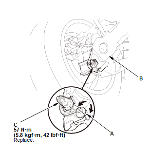
1. Hold the adjusting bolt (A) on the trailing arm (B), and remove the self-locking nut (C)
2. Replace the self-locking nut with a new one, and lightly tighten it.
NOTE:
- Always use a new self-locking nut whenever it has been loosened.
- Reassemble the adjusting bolt and the adjusting cam plate with the eccentric facing up.
3. Adjust the rear toe by turning the adjusting bolt until the toe is correct
4. Tighten the self-locking nut to the specified torque while holding the adjusting bolt.
- 4. Front Toe - Adjust
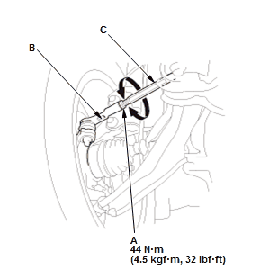
1. Loosen the tie-rod end locknuts (A) while holding the flat surface sections (B) of the tie-rod end with a wrench, and turn both tie-rods (C) until the front toe is within specifications
2. After adjusting, tighten the tie-rod end locknuts to the specified torque. Reposition the rack-end boot if it is twisted or displaced.
- 5. VSA Sensor Neutral Position - Memorize
- 6. Steering Angle Sensor Neutral Position - Clear