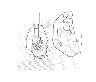
Steering Gearbox Removal & Installation: Installation
NOTE: Using clean solvent and a brush, wash any oil and dirt off the end of the steering gearbox. Avoid any electrical parts. Blow dry with compressed air.
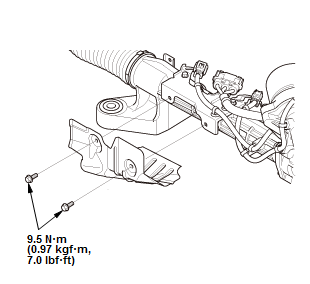
- 1. Power Steering Heat Shield - Remove
- 2. Steering Gearbox - Install
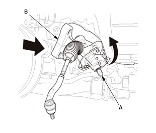
1. Apply vinyl tape to the splines on the pinion shaft (A)
2. Slide the steering gearbox (B) between the front subframe and body.
NOTE: Be careful not to damage the steering gearbox boot and the pinion shaft.
3. Install the steering gearbox until the steering gearbox is in position.
- 3. Pinion Shaft Grommet - Install
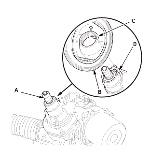
1. Remove the vinyl tape (A) from pinion shaft
2. Install the pinion shaft grommet (B)
3. Align the lug portion (C) in the pinion shaft grommet with the cutout portion (D) on the steering gearbox.
- 4. Front Subframe - Move
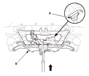
1. Turn the lip (A) of the pinion shaft grommet
2. Raise the front subframe (B) up to the body, then restore the pinion shaft grommet back to proper position.
NOTE: Be sure that the pinion shaft grommet is secure in place. Make sure the lip of the pinion shaft grommet is not turned up. Incorrect installation can cause leakage of water and mud, or noise.
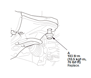
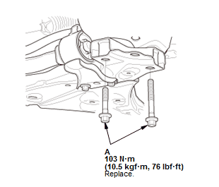
- 5. Front Subframe Mounting Bolt - Loosely Install
 Courtesy of HONDA, U.S.A., INC.
 Courtesy of HONDA, U.S.A., INC.
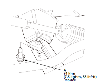
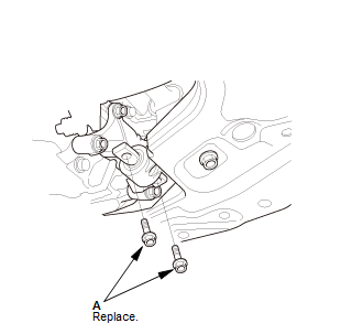
1. Loosely install a new front subframe mounting bolts (A) on both sides.
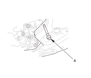
2. Loosely install a new mid mounting bolt (A) on both sides.
- 6. Front Subframe - Tighten
- 7. Lower Torque Rod - Connect
1. Loosely install new lower torque rod mounting bolts (A).
2. Loosen the lower torque rod mounting bolt (A) to the subframe side. 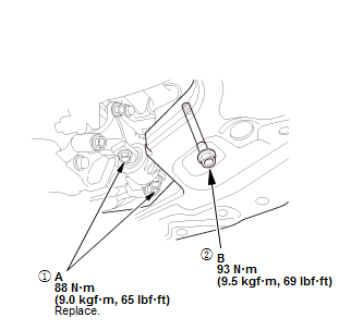 Courtesy of HONDA, U.S.A., INC.
3. Tighten the lower torque rod mounting bolts (A) to the oil pan side
4. Tighten the lower torque rod mounting bolt (B) to the subframe side.
- 8. Steering Gearbox Stiffener - Install
Left side
Fig 5: Steering Gearbox Stiffeners & Steering Gearbox Mounting Bolts (Left Side) With Torque Specifications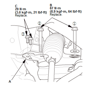 Courtesy of HONDA, U.S.A., INC.
Right side
Fig 6: Steering Gearbox Stiffeners & Steering Gearbox Mounting Bolts (Right Side) With Torque Specifications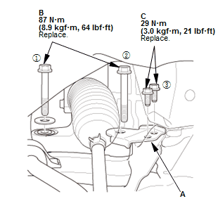 Courtesy of HONDA, U.S.A., INC.
1. Install the steering gearbox stiffeners (A)
2. Loosely tighten new steering gearbox mounting bolts on both sides (B)
3. Loosely tighten new stiffener mounting bolts (C)
4. Tighten the steering gearbox mounting bolts and the stiffener mounting bolts to the specified torque in the sequence shown.
- 9. Connectors - Connect
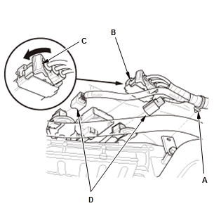
1. Install the harness clip (A)
2. Connect the connector (B), then pulling down the lever (C), and confirm the connector is fully seated
3. Connect the connectors (D).
- 10.Exhaust Pipe A and Under-Floor TWC - Install
- 11.No. 1 Propeller Shaft - Connect
- 12.Front Floor Undercover - Remove - Refer to: Middle Floor Undercover Removal and InstallationRear Floor Undercover Removal and InstallationFront Floor Undercover Removal and Installation
- 13.Splash Shield - Install
- 14.Stabilizer Link - connect
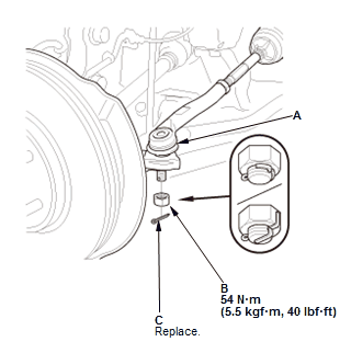
- 15. Tie-Rod End Ball Joint - Connect
1. Wipe off any grease contamination from the ball joint tapered section and threads
2. Connect the tie-rod ball joint (A) to the knuckle
3. Install the nut (B)
4. Install a new cotter pin (C).
NOTE: Bend the cotter pin as shown.
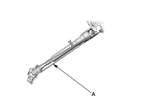
- 16. Steering Column Lower Slide Shaft - Release
1. Cut the wire (A).
- 17. Steering Wheel - Release
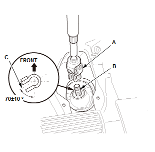
- 18. Steering Joint - Connect
1. Set the rack in the straight ahead driving position
2. Slip the lower end of the steering joint (A) onto the pinion shaft (B).
NOTE: Position the steering column by aligning the gap (C) within the angle.
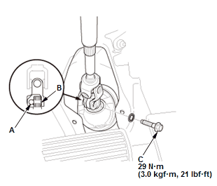
3. Align the bolt hole (A) on the steering joint with the groove (B) around the pinion shaft
4. Loosely install the steering joint bolt (C)
5. Be sure that the joint bolt is secure in the groove in the pinion shaft
6. Pull on the steering joint to make sure that the steering joint is fully seated
7. Tighten the steering joint bolt to the specified torque.
- 19. Steering Joint Cover - Install
- 20.Front Wheel - Install
- 21.12 Volt Battery Terminal - Reconnect
- 22. Steering Gearbox - After Install Symptom Check
1. With the tires raised off the ground, check for the following symptoms by turning the steering wheel fully to the right and left several times.
Symptom Probable cause Rubbing sound coming from the lower steering column area. Steering column joint is contacting the cover. Noise from the lower steering column area, or a rough feeling during steering. Poor engagement of the pinion shaft serrations. Noise from around the steering wheel during steering. Poor engagement of the SRS cable reel with the steering wheel, or a damaged cable reel. - 23. Steering Gearbox After Install - Check
1. After installation, check these items:
- Start the engine, allow it to idle, and turn the steering wheel from lock to lock several times.
- Check that the EPS indicator does not come on.
- Check the steering wheel spoke angle. If steering spoke angles to the right and left are not equal (steering wheel and rack are not centered), correct the engagement of the joint/pinion shaft splines.
- 24.Wheel-Alignment - Check
- 25.VSA Sensor Neutral Position - Memorize
- 26.Steering Angle Sensor Neutral Position - Clear